Drafting of various geometries using Chamfer, Fillet tool in AutoCad
AIM: To draw the various geometries using Chamfer, Fillet tool using AutoCAD software
INTRODUCTION: The main objective of this assignment is to get in touch with various tools Line, Circle, Offset, Chamfer, Fillet.
Commands Used:
- Line
- Circle
- Chamfer
- Fillet
- Mirror
- Trim
- Move
- Rotate
PROCEDURE:
Drawing 1:
- Open AutoCAD software
- Start new drawing
- Type L in the command line and click Enter
- Specify first point: 1,1
- Specify next point: @3,0
- Specify next point: @2.12<45
- Specify next point: @2.83<135
- Specify next point: @-2,0
- Specify next point: @0,-2.5
- Press Esc
- Type O in the command line and click Enter
- Enter offset distance: 1.0
- Select the object and move the cursor upwards
- Type O in the command line and click Enter
- Enter offset distance: 1.5
- Select the object and move the cursor upwards
- Type C in the command line and click Enter
- Draw a circle of diameter 1.20 at 1m height at the midpoint of 3m line
- Type C in the command line and click Enter
- Draw a circle of diameter 0.80 at 2.50m height at the midpoint of 3m line
- Type E in the command line and click Enter
- Select the objects and erase it
- Type DIM in the command line and click Enter
- Select the object and the dimensions are displayed
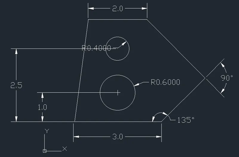
Drawing 2:
- Open AutoCAD software
- Start new drawing
- Type L in the command line and click Enter
- Specify start point: 2,5
- Specify next point: @2'-10"<45
- Specify next point: @0,1'-9"
- Specify next point: @-8',0
- Specify next point: @0,2'-5"
- Switch on polar tracking 30,60,90,.
- Place the cursor at 300 degrees and type 3'
- Again place the cursor at 30 degrees and type 2'-6"
- Type DIM in the command line an click Enter
- Select the objects and dimensions are displayed
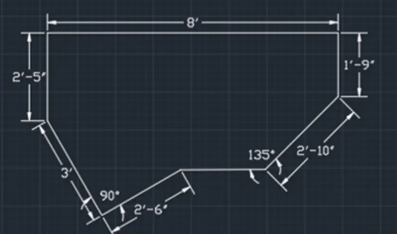
Drawing 3:
- Open AutoCAD software
- Start new drawing
- Type REC in the command line and click Enter
- Specify the starting point
- Specify the next point or [Area Dimensions Rotation]
- Click on dimensions
- Enter the length: 5'-0.1"
- Enter the width: 3'-3.0"
- Specify other corner
- Type CHAMFER in the command line and click Enter
- Select first line
- Select second line or [Undo Distance Trim Angle Polyline Trim Multiple]: d
- Specify first chamfer distance: 2'-3.5"
- Specify second chamfer distance: 1'-9"
- Click Enter
- Type L in the command line and click Enter
- Specify start point
- Specify next point: @1'-3.0"
- Specify next point: @1'-6.0"
- Type C in the command line and click Enter
- Specify center point of the circle
- Specify radius of the circle or [Diameter]
- Click on diameter
- Specify diameter of the circle: 1'-6.0"
- Type E in the command line and click Enter
- Select the object and erase it
- Type DIM in the command line and click Enter
- Select the objects and dimensions are displayed
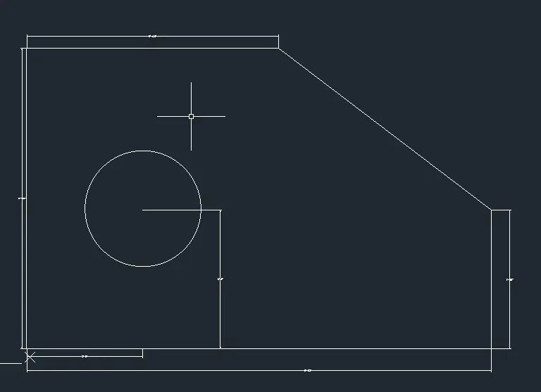
Drawing 4:
- Open AutoCAD software
- Start new drawing
- Type L in the command line and click Enter
- Specify start point: 1,1
- Specify next point: @3,0
- Specify next point: @0,-0.5
- Specify next point: @2.5,0
- Specify next point: @0,2.5
- Specify next point: @-2,0
- Specify next point: @0,3
- Specify next point: @-2.5,0
- Specify next point: @0,2
- Press Esc
- Type L in the command line and click Enter
- Specify start point
- Specify next point: @0,3
- Specify next point: @1,0
- Type DIMLINEAR in the command line and click Enter
- Select the objects and dimensions are displayed
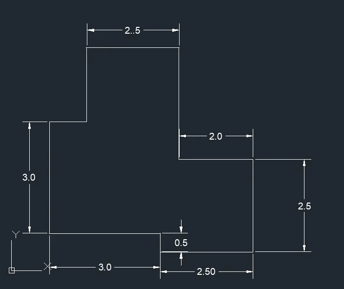
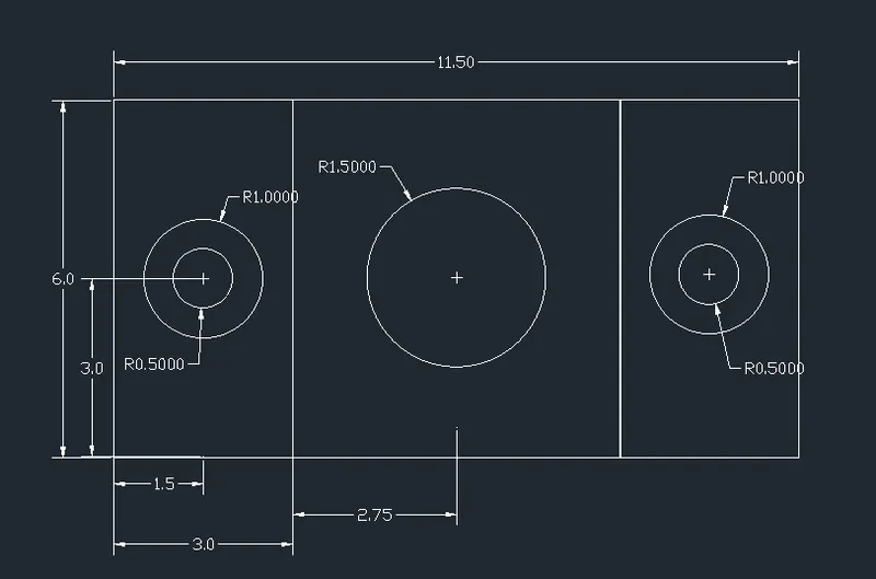
Diagram 5:
- Open AutoCAD software
- Start new drawing
- Type REC in the command line and click Enter
- Specify first corner point
- Specify second corner point or [Area Dimensions Rotation]
- Click on Dimensions
- Enter the length: 3
- Enter the width: 6
- Specify other corner
- Type L in the command line and click Enter
- Specify start point
- Specify next point: @1.5,0
- Specify next point: @0,6
- Turn on Midpoint in Object Snap
- Type C in command line and click Enter
- Specify centre point of circle
- Specify radius of circle: 0.5
- Type OFFSET in the command line and click Enter
- Specify offset distance: 0.5
- Select the circle and click outside of the circle
- Type REC in the command line and click Enter
- Specify first corner point
- Specify second corner point or [Area Dimensions Rotation]
- Click on dimensions
- Enter the length: 5.5
- Enter the width: 6
- Specify other corner
- Type L in the command line and click Enter
- Specify start point
- Specify next point: @2.75,0
- Specify next point: @0,6
- Type C in the command line and click Enter
- Specify centre point of circle
- Specify radius of circle: 1.5
- Type REC in the command line and click Enter
- specify first corner point
- Specify second corner point or [Area Dimensions Rotation]
- Click on dimensions
- Enter the length: 3
- Enter the width: 6
- Specify other corner
- Type L in the command line and click Enter
- Specify start point
- Specify next point: @1.5,0
- Specify next point: @0,6
- Type C in the command line and click Enter
- Specify centre point of circle
- Specify radius of circle: 0.5
- Type OFFSET in the command line and click Enter
- Specify offset distance: 0.5
- Select the circle and click outside of the circle
- Select the unwanted lines and erase it
- Type DIMLINEAR and DIMRADIUS in the command line and click Enter
- Select the objects and dimensions are displayed
Drawing 6:
- Open AutoCAD software
- Start new drawing
- Type REC in the command line and click Enter
- Specify first corner point
- Specify next corner point or [Area Dimensions Rotation]
- Click on dimensions
- Enter the length: 1.5
- Enter the width: 0.5
- Specify last corner point
- Type L in the command line and click Enter
- Specify start point
- Specify next point: @0,1.5
- Specify next point: @0.5,0
- Specify next point: @0,-1.5
- Specify next point: @0.5,0
- Specify next point: @0,1.5
- Specify next point: @0.5,0
- Specify next point: @0,-1.5
- Click Esc
- Type L in the command line and click Enter
- Specify start point
- Specify next point: @0.5,0
- Click Esc
- Type L in the command line and click Enter
- Specify start point
- Specify next point: @0,-0.5
- Specify next point: @1.5,0
- Specify next point: @0,1.5
- Specify next point: @-0.5,0
- Specify next point: @0,-1
- Specify next point: @-1,0
- Join the top left corner and the bottom up corner and click Esc
- Select the first diagram and type the command COPY in command line
- Click Enter and make a copy of it where we need
- Rotate the object as per requirement by giving a command ROTATE in command line
- Erase unwanted lines
- Type DIMLINEAR in the command line and click Enter
- Select the objects and dimensions are displayed
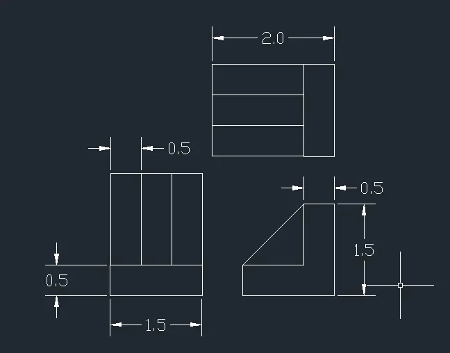
Diagram 7:
- Open AutoCAD software
- Start new drawing
- Type L in the command line and click Enter
- Specify start point
- Specify next point: @0,-100
- Specify next point: @210,0
- Specify next point: @0,75
- Type F in the command line and click Enter
- Select first line
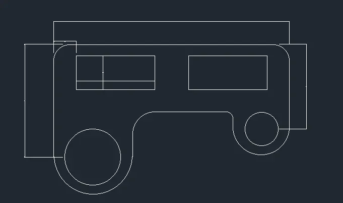
- Specify radius as 15
- Select second line and click Enter
- Type F in the command line and click Enter
- Select first line
- Select radius as 15
- Select second line and click Enter
- Type L in the command line and click Enter
- Specify start point
- Specify next point: @70,0
- Click Esc
- Type L in the command line and click Enter
- Specify start point
- Specify next point: @-50,0
- Click Esc
- Type C in the command line and click Enter
- Turn on midpoint in Object Snap
- Specify centre point and enter radius of circle: 25
- Type C in the command line and click Enter
- Specify centre point and enter radius of circle: 15
- Select start end radius option from arc menu in draw panel
- Specify start point and endpoint
- Radius of arc: 35
- Select start end radius option from arc menu in draw panel
- Specify start and end point
- Radius of arc: 25
- Type L in the command line and click Enter
- Specify start point
- Specify next point: @20,0
- Specify next point: @0,40
- Click Esc
- Type L in the command line and click Enter
- Specify start point
- Specify next point: @0,-10
- Specify next point: @70,0
- Specify next point: @0,-30
- Specify next point: @-70,0
- Click Esc
- Select and erase unwanted lines
- Type Move in the command line and click Enter
- Select the object and click enter
- Specify the base point or [Displacement]
- Click displacement
- Specify displacement from base point: 100
- Click Esc
- Type L in the command line and click Enter
- Specify start point
- Specify next point: @0,-20
- Draw the perpendicular line to it
- Join the arcs with the line command
- Type F in the command line and click Enter
- Select the first object
- Specify the Radius as 20
- Select the second object and click Enter
- Type F in the command line and click Enter
- Select the first object
- Specify the radius as 6
- Select the second object and click Enter
- Erase unwanted lines
- Type DIM in the command line and click Enter
- Select the objects and then dimensions are displayed
Drawing 8:
- Open AutoCAD app
- Start new drawing
- Type C in the command line and click Enter
- Specify centre point of circle: 5,5
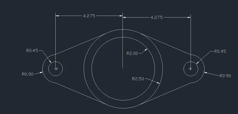
- Specify radius of circle: 2
- Type O in the command line and click Enter
- Specify offset distance: 0.5
- Select the object and click outside of the circle
- Type L in the command line and click Enter
- Specify start point: 5,5
- Specify next point: @4.275,0
- Click Esc
- Type L in the command line an click Enter
- Specify start point: 5,5
- Specify next point: @-4.275,0
- Click Esc
- Type O in the command line and click Enter
- Specify offset distance: 0.9
- Select the object and click on top and bottom
- Close it with the lines at both sides
- Trim and erase the top and bottom line
- Type C in the command line and click Enter
- Specify centre point of the circle
- Specify radius of the circle: 0.45
- Type C in the command line and click Enter
- Specify centre point of the circle
- Specify radius of the circle: 0.45
- Select start end radius option from arc menu in the draw panel
- Specify start and end point
- Radius of arc: 0.90
- Select start end radius option from arc menu in the draw panel
- Specify start and end point
- Radius of arc: 0.90
- Turn on Tangent in Object Snap
- Draw lines from the points to the tangents top and bottom of the big circles
- Trim unwanted lines
- Type DIMLINEAR and DIMRADIUS in the command line and click Enter
- Select the objects and then dimensions are displayed
Drawing 9:
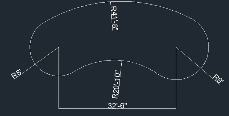
- Open AutoCAD software
- Start new drawing
- Type L in the command line and click Enter
- Specify start point
- Specify next point: 32'-6",0
- Type C in the command line and click Enter
- Specify centre point of the circle
- Specify radius of the circle: 8'
- Type C in the command line and click Enter
- Specify centre point of the circle
- Specify radius of the circle: 9'
- Type C in the command line and click Enter
- Select tan, tan, radius
- Select first tangent by clicking on the top tangent of left circle
- Select second tangent by clicking on the top tangent of the right circle
- Specify radius of circle: 41'-8"
- Type C in the command line and click Enter
- Select tan, tan, radius
- Select first tangent by clicking on the bottom tangent of left circle
- Select second tangent by clicking on the bottom tangent of right circle
- Specify radius of circle: 20'-10"
- Trim and erase unwanted lines
- Type DIMLINEAR and DIMRADIUS in the command line and click Enter
- Select the objects and then dimensions are displayed
Drawing 10:
- Open AutoCAD software
- Start new drawing
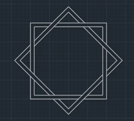
- Type REC in the command line and click Enter
- Specify first corner point
- Specify next corner point or [Area Dimensions Rotation]
- Click on dimensions
- Enter the length: 10
- Enter the width: 10
- Specify other corner point
- Type O in the command line and click Enter
- Specify offset distance: 0.5
- Select the object and click inside of it
- Type ROTATE in the command line and click Enter
- Select the object and rotate at an angle of 45 degrees by selecting a base point
- Type MOVE in the command line and click Enter
- Select the object and move it to the centre of it
- Trim unwanted lines
- Type DIMLINEAR in the command line and click Enter
- Select the objects and then dimensions are displayed
Drawing 11:
- Open AutoCAD app
- Start new drawing
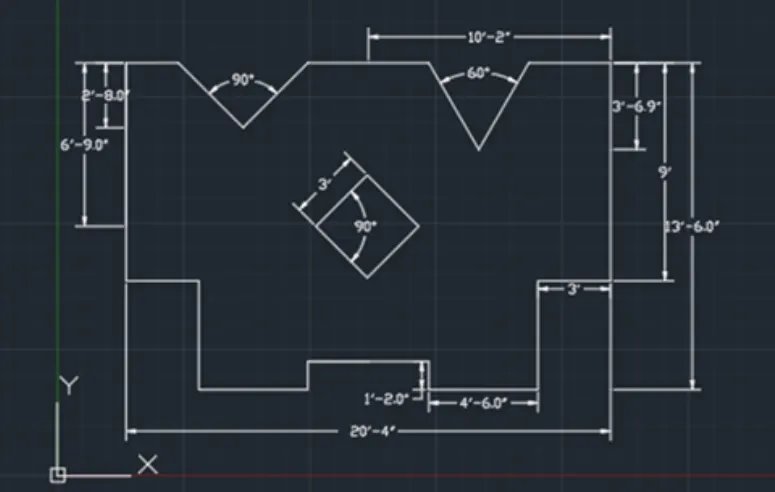
- Type L in the command line and click Enter
- Specify start point
- Specify next point: @2'-6",0
- Specify next point: @0,-1'-2"
- Specify next point: @4'-6",0
- Specify next point: @0,4'-6"
- Specify next point: @3',0
- Specify next point: @0,9'
- Click Esc
- Type MIRROR in the command line and click Enter
- Select mirror object
- Specify first point
- Specify second point
- Erase source object <Yes No>: No
- Type L in the command line and click Enter
- Specify start point
- Specify next point: @0,-3'-7"
- Specify next point: @-8'-7",0
- Turn on polar tracking 30,60,90 degrees
- Type L in the command line and click Enter
- Specify start point
- Specify next point: @0,12'-4"
- Specify next point: @-5'-2",0
- Specify next point: @0,-12'-4"
- Click Esc
- Type L in the command line and click Enter
- Specify start point
- Specify next point by using polar tracking of 30degrees
- Specify next point by using polar tracking of 30degrees
- Join the line to the edge
- Click Esc
- Type L in the command line and click Enter
- Change polar tracking 45,90,135
- Specify next point
- Specify next point by using polar tracking of 45degrees
- Specify next point by using polar tracking of 45degrees
- Join the line to the edge
- Click Esc
- Type L in the command line and click Enter
- Specify start point
- Specify next point: @0,-6'-9"
- Specify next point: @10'-2",0
- Specify next point: @0,-6'-7"
- Specify next point: @0,1'-2"
- Turn on polar tracking 45,90,135
- Specify next point: 3'
- Specify next point: 3'
- Specify next point: 3'
- Specify next point: 3' and click Esc
- Erase unwanted lines
- Type DIMLINEAR and DIMANGULAR in the command line and click Enter
- Select the objects and then dimensions are displayed
RESULT:
The given geometries are drafted using AutoCAD in accurate measurements
CHALLENGE ACCOMPLISHED