Creating a Residence Layout, Seating plan, Toilet and Utility room plan using AutoCad
1. Residence plan
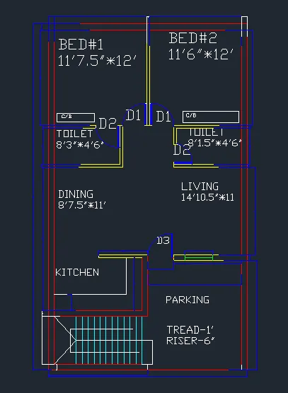
Aim: To sketch the layout of a residential building as per the dimensions mentioned in the attachment
Introduction: The given drawings in the attachment are sketched by using AutoCAD software
Commands Used
- Units
- Limmax
- Xline
- Trim
- Offset
- Fillet
- Line
- Circle
Procedure:
- Open AutoCAD software
- Start new drawing
- Type UN in the command line and click Enter
- Set it to the Engineering and choose precision
- Type LIMMAX in the command line and click Enter
- Set it to the 100',100' and click enter
- Type Z in the command line and click Enter
- Click on All and click enter
- Type XL in the command line and click enter
- Specify the point or [Hor Ver Ang Bisect Offset]
- Click on Horizontal at once and then on Vertical once
- Type Z in the command line and click Enter
- Click on All and click enter
- Type Trim in the command line and click Enter
- Select the object to trim in -X & -Y direction
- Type Offset in the command line and click Enter
- Specify offset distance as 9"
- Select the object and move upwards upwards as well as right side
- Draw a line of 25' in x- direction and then 43'6.5" in y-direction
- Make offsets 9" for both x&y direction on the right side
- Trim unwanted lines
- Type Offset in the command line and click Enter
- Specify offset distance as 6' in y-direction as well as 9"
- Take line command and draw 8'1.5" towards x-direction
- Draw 6'4" in -x direction and 0.45 in -y direction
- Again draw 5'5" in x-direction and 6'8" in -y direction
- Type offset in the command line and click enter
- Specify offset distance as 2' and select the object, move it to upward as well as left side
- Trim unwanted lines
- Type L in the command line and click Enter
- Specify start point and next point at a distance of 13'9.5"
- Draw a line 9'5" towards -x direction, 9" in -y direction and 8'6" in x direction
- Trim unwanted lines
- Make offset at 11' towards y-direction as well as 4.5"
- Again 4'6" of offset in y-direction and of 4.5"
- Draw a line 2' from previous point and make offset of 4.5"
- Make offset 11'6" from top right corner and 4.5" from last point
- Again 18'0.5" of offset from left middle as well as 4.5" from previous line
- Draw a line 4'6" towards y direction and make offset of 4.5"
- Make offset of 12' from top left edge as well as 4.5" from last line
- Close the lines at edges as per the dimensions
- Fix the doors by using of circle command and trim unwanted lines
- Draw the lines for windows by using offset as per required dimension
- Draw the stairs by using offset
- Type DIMLINEAR in the command line and click enter
- Select the objects and then dimensions are displayed
- Click on Text icon which is in tool bar and specify the point in the layout
- Specify height of text and angle of text then place the cursor and make use of it
- Then go to layer properties in the tool bar and add layers individually for External-Internal walls, doors, windows, dimensions, text etc., based on the layout
- Mention the colours for each one differently and give lineweight, linetype according to the requirement
- Select the portions which belongs to same category then go to layers and opt related one, click enter
- Now the layout portions will be displayed individually
- We have several options like on, lock, freeze, plot, transparency used for several purposes on the basis of layers
- Type Layoff or Layon in the command line and click enter to see specific layers accordingly
Result:
The layout of Residential plan is sketched as per the dimensions by using AutoCAD software and the dimensions are mentioned clearly
2. OUTDOOR SEATING WITH CANOPY
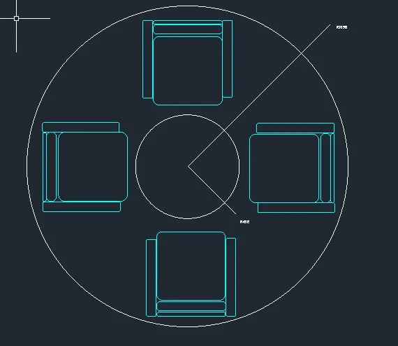
Aim: To sketch the layout of outdoor seating of canopy as per the dimensions mentioned in the attachment
Introduction: The given drawings in the attachment are sketched by using AutoCAD software
Commands Used
- Units
- Limmax
- Xline
- Move
- Rotate
- Fillet
- Rectangle
- Circle
Procedure:
- Open AutoCAD software
- Start new drawing
- Type UN in the command line and click Enter
- Set it to the Decimal and choose precision as well as mainly change into millimetres
- Type LIMMAX in the command line and click Enter
- Set it to the 100',100' and click enter
- Type Z in the command line and click Enter
- Click on All and click enter
- Type C in the command line and click Enter
- Specify the centre of circle : 1,1
- Specify the radius of circle as 1398 for one and 452 as second
- Type REC in command line and click enter
- Specify first and second corner randomly
- Type Fillet in command line and click enter
- Select first object
- Select second object or [Radius]
- Click on radius and specify fillet radius
- Select second object and click enter
- Make 4 more rectangles similarly by using REC and fillet for making chair
- Type Move in the command line and click Enter
- Select the objects and click enter then specify the base point and make a move
- Again select the chair and make a reference copy to move 4 different sides
- Type Rotate in the command line and click Enter
- Select the object then click enter and specify base point to rotate it
- Select the object and make a move by specifying base point
- All the 4 copies are set into a required place
- Type DIMRADIUS in the command line and click Enter
- Select the circle or arc and then dimensions are dispalyed
Result:
The layout of the outdoor seating of a canopy is sketched as per dimensions mentioned in the attachment using AutoCAD software
3. Part plan of toilers and utilities room
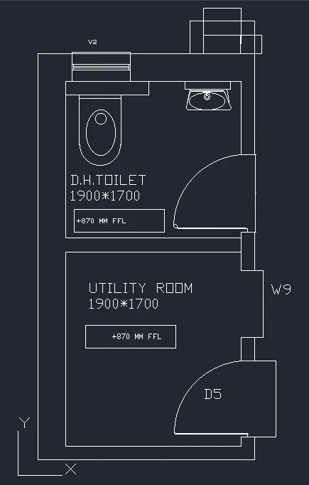
Aim: To sketch the layout of the part plan of toilers and utilities room as per the dimensions mentioned in the attachment
Introduction: The given drawings in the attachment are sketched by using AutoCAD software
Commands Used
- Units
- Limmax
- Xline
- Offset
- Line
- Fillet
- Ellipse
- Circle
Procedure:
- Open AutoCAD software
- Start new drawing
- Type UN in the command line and click Enter
- Set it to the Decimal and choose precision as well as mainly change into millimetres
- Type LIMMAX in the command line and click Enter
- Set it to the 100',100' and click enter
- Type Z in the command line and click Enter
- Click on All and click enter
- Type XL in the command line and click enter
- Specify the point or [Hor Ver Ang Bisect Offset]
- Click on Horizontal at once and then on Vertical once
- Type Z in the command line and click Enter
- Click on All and click enter
- Type Trim in the command line and click Enter
- Select the object to trim in -X & -Y direction
- Type Offset in the command line and click Enter
- Specify offset distance as 300mm in x-direction
- Type L in the command line and click enter
- Specify first point
- Specify next point as 1900mm in x-direction and 4400mm in y-direction
- Make offset 300mm at top side and 150mm at bottom
- Again type Offset in the command line and click Enter
- Specify offset distance 2100mm from bottom and 150mm from last line
- Trim the lines for openings as per dimensions and close the walls
- Type C in the command line and click Enter
- Specify center point and draw circle
- Trim all 3 sides of it
- Make the wall cut at top side for fitting of window as per dimensions
- Draw lines and make offsets for it as well as trim unwanted llines
- Type Ellipse in the command line and click Enter
- Specify the center and end point to create ellipse
- Draw the circle in it
- Again draw the lines in closed manner and then use fillet for it
- Type C in the command line and click Enter
- Specify center point and draw the circles required
- Draw the tangent to the rectangle and the top line
- Draw the circles for setting of doors and trim unwanted lines
- Type DIMLINEAR in the command line and click Enter
- Select the objects and then dimensions are displayed
Result:
The layout of the part plan of toilers and utilities room is sketched as per the dimensions mentioned in the attachment using AutoCAD software
CHALLENGE ACCOMPLISHED