Drafting of various geometries using Chamfer, Fillet tool in AutoCad
AIM
To create geometry given below
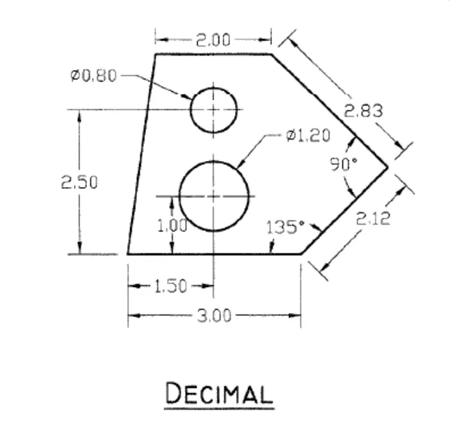
INTRODUCTION
Here we are using line tool,circle,
Relative polar coordinates method for drawing the polygon
Here we are using unit type as Decimal
PROCEDURE
Step 1 :Open AUTOCAD
For unit measurement setting
Enter the command ‘UN’
Click on the type as ‘Decimal’
Precision 0.00
Then click Enter
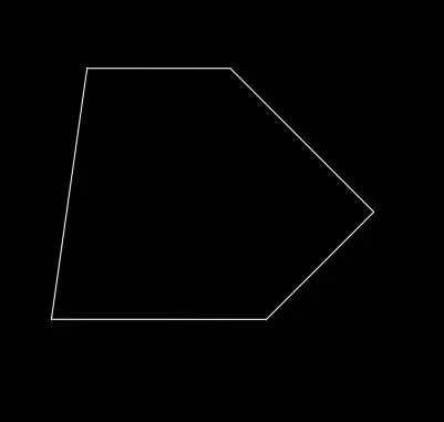
Step 2 :Enter the command for line tool ‘L’
Click ORTHOMODE off
Enter the starting point= 0,0
Enter the next point =(@3,<0)
Enter the next point =(@2.12,<45)
Enter the next point =(@2.83,<135)
Enter the next point =(@2,<180)
Then click on ‘close’
Step 3:Enter the command for circle ‘C’
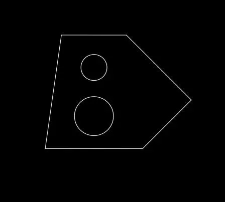
Specify the center =(1.5,2.5)
Specify the radius =0.40
Step 4:Enter the command for circle ‘C’
Specify the center =(1.5,1)
Specify the radius =0.6
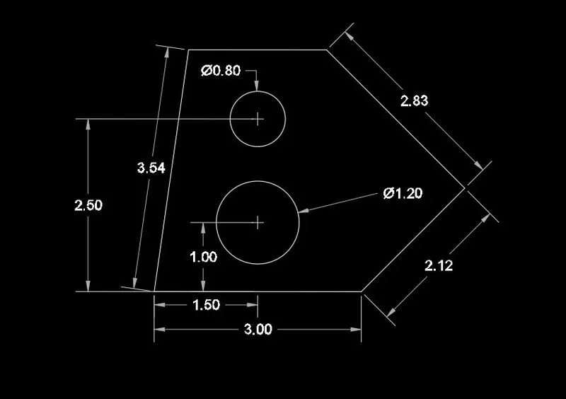
Step 5 :mark the dimensions
RESULT
AIM
To create geometry given below
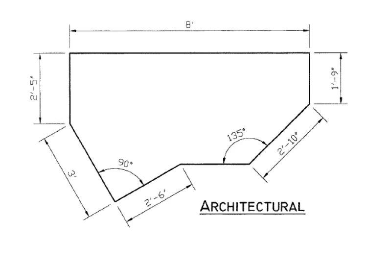
INTRODUCTION
Here we are using line tool,circle,
Relative polar coordinates method for drawing the polygon
Here we are using unit type as Architectural
PROCEDURE
Step 1 :Open AUTOCAD
For unit measurement setting
Enter the command ‘UN’
Click on the type as ‘Architectural’
Precision 0.00
Then click Enter
Step 2 :Enter the command for line tool ‘L’
Enter the starting point= 0,0
Enter the next point =(@2’10”,<45)
Enter the next point =(@1’9”,<90)
Enter the next point =(@8’,<180)
Enter the next point =(@2’5”,<270)
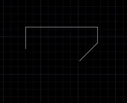
Step 3:For construction line Enter ‘xl’
Then Enter ‘h’ for horizontal line
Place the line on the starting point of the drawing
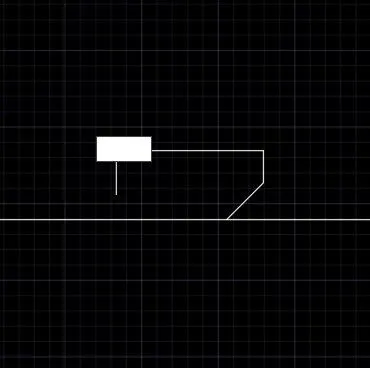
Step 4:Enter the command for line tool ‘L’
Specify first point as the finishing point of the drawing
Draw line 3’ downawar and
2’6” towards right
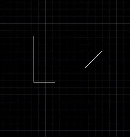
Step 5:Select the the last drawn two lines
Enter the command ‘RO’(to rotate)
Then enter ’R’
Then specify first point
Then second point as the end of the two line
Step 6 : Rotate the two line
When the line touches the construction line ,shows the nearest point
Then click Enter
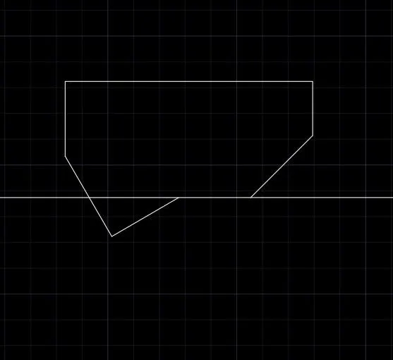
Step 7 : Enter ‘Trim’ command to trim unwanted lines
Step 8 : mark the dimensions
RESULT
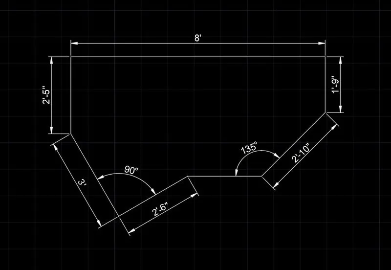
AIM
To create geometry given below
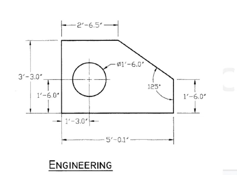
INTRODUCTION
Here we are using line tool,circle,Chamfer
Relative polar coordinates method for drawing the polygon
Here we are using unit type as Engineering
PROCEDURE
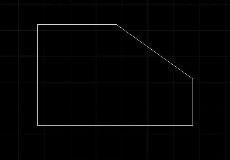
Step 1 : enter ‘REC’ command for rectangle tool
Specify the first pint = 0,0
Click on dimension
Length =5’01”
Width =3’30”
Then click enter
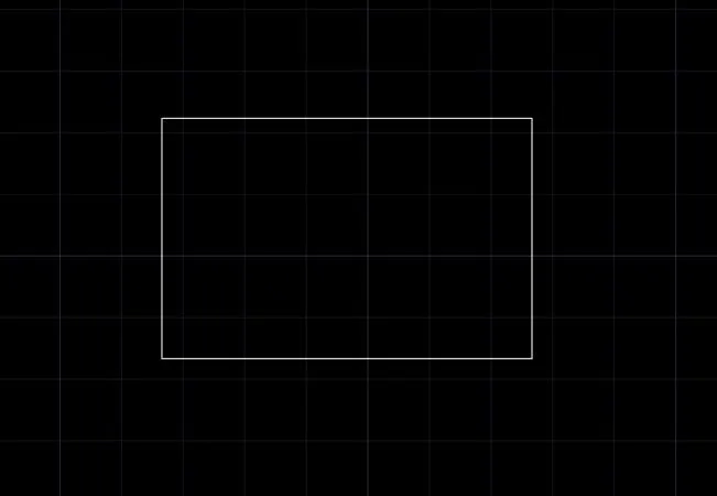
Step 2 :Enter ‘CHA’ for chamfer command
Then click distance
Specify first distance =1’9”
Specify second distance =2’5.6”
Then select the two lines
Then enter
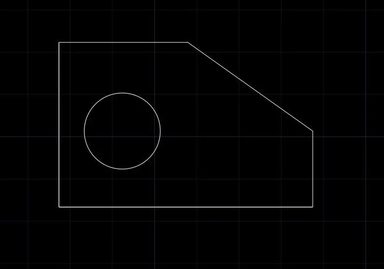
Step 3 :Enter circle command
Specify the center =(1’3”,1’6”)
Then click on diameter
Enter the value =1’6”
Then enter
Step 4 : mark the dimensions
RESULT
AIM
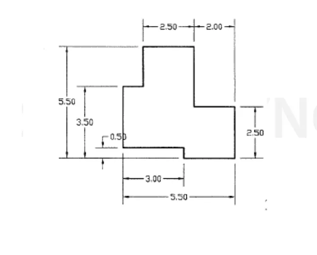
To create geometry given below
INTRODUCTION
Here we are using line tool,circle,
Direct entry method for drawing the figure
Here we are using unit type as Decimal
PROCEDURE
Step 1:Enter the line command
Specify the first point
Then 3 unit upward
1 towards right
2 upward
2.5 towards right
3 downwards
2 towards right
2.5 downwards
2.5 towards right
0.5 upwards
3 towards right
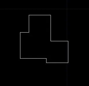
Step 2 : Mark the dimensions
RESULT
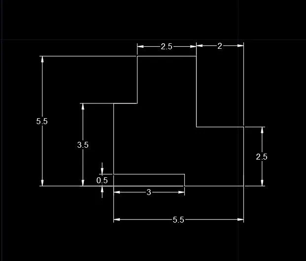
AIM
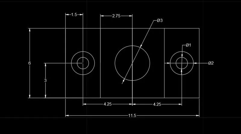
To create geometry given below
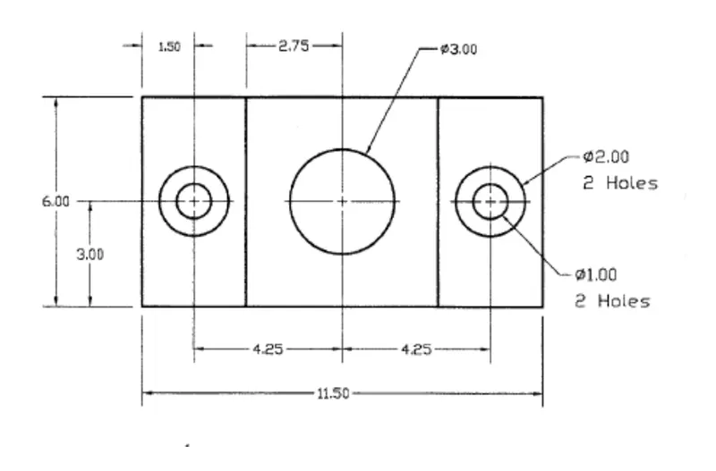
INTRODUCTION
Here we are using line tool,circle,
Direct entry method for drawing the figure
Here we are using unit type as Decimal
PROCEDURE
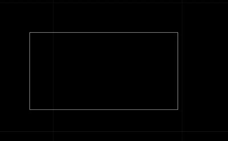
Step 1:Enter the rectangle command
Specify the first point =(0,0)
Click on dimensions
Enter the length 11.5
Enter the width 6
Step 2:Select the rectangle
Enter explode command
Then enter
(the rectangle is exploded to lines)
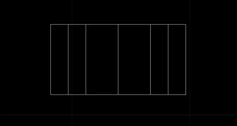
Step 3 :Enter ‘offset’ command
Then specify the distance 3
Take offset on both sides
Step 4 ::Enter ‘offset’ command
Then specify the distance 1.5
Teke offset on both sides
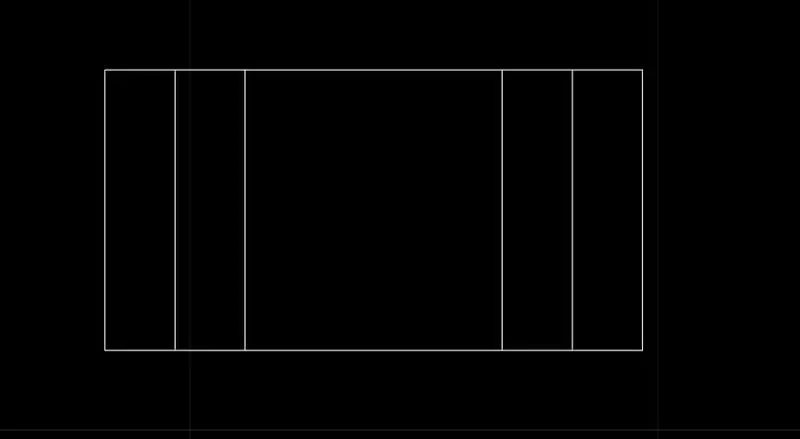
Step 5 ::Enter ‘offset’ command
Then specify the distance 5.75
Take offset from left side
Step 6: Enter the circle command
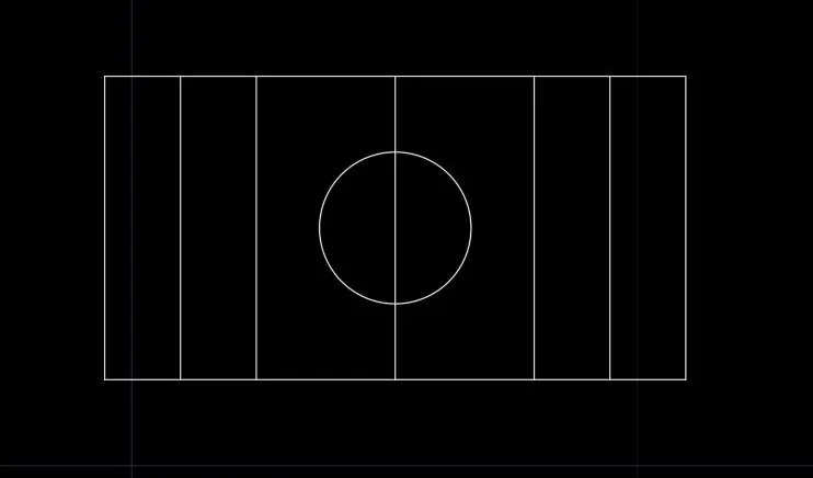
Specify the center of the circle as center of the fourth line from left
Then click on diameter
Then enter the value 3
Then enter
Step 7: Enter the circle command
Specify the center of the circle as center of the second line from left
Then click on diameter
Then enter the value 2
Then enter
Enter the circle command
Specify the center of the circle as center of the second line from left
Then click on diameter
Then enter the value 1
Then enter
Step 8: Enter the circle command
Specify the center of the circle as center of the second line from right
Then click on diameter
Then enter the value 2
Then enter
Enter the circle command
Specify the center of the circle as center of the second line from right
Then click on diameter
Then enter the value 1
Then enter
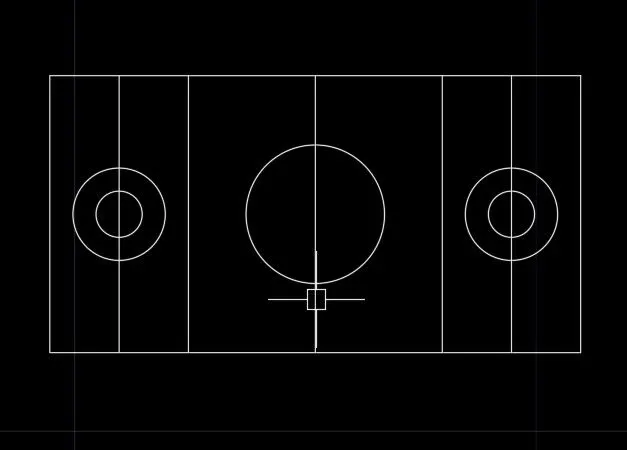
Step 9 : trim unwanted line using ‘Trim’ command
Step 10: Mark the dimensions
RESULT
AIM
To create geometry given below
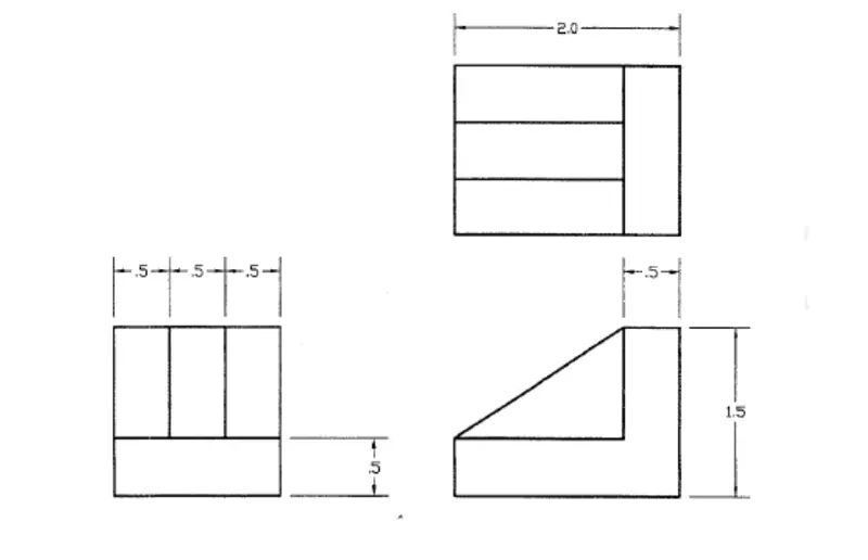
INTRODUCTION
Here we are using line tool,circle,
Direct entry method for drawing the figure
Here we are using unit type as Decimal
PROCEDURE
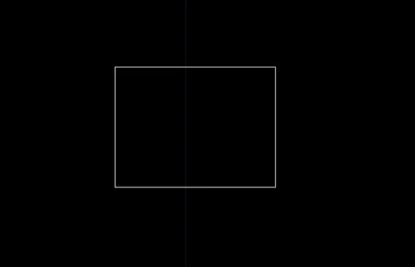
Step 1:Enter the rectangle command
Specify the first point =(0,0)
Click on dimensions
Enter the length 2
Enter the width 1.5
Step 2:Select the rectangle
Enter explode command
Then enter
(the rectangle is exploded to lines)
Step 3 :Enter ‘offset’ command
Then specify the distance 0.5
Take offset from left side
Then enter
Step 4 :Enter ‘offset’ command
Then specify the distance 0.5
Take offset from lower line
Then enter
Step 5 :Enter ‘offset’ command
Then specify the distance 0.5
Take offset from upper line
Then enter
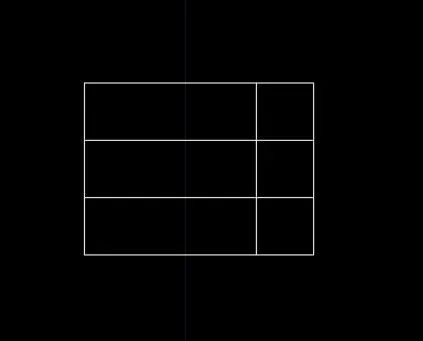
Step 6 : trim unwanted line using ‘Trim’ command
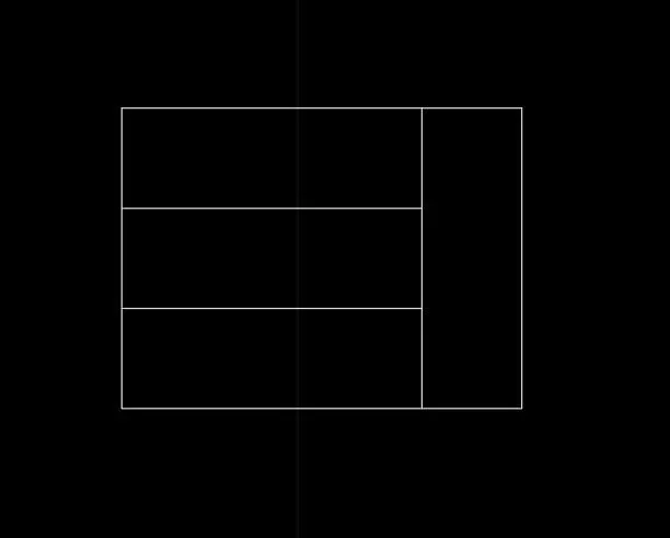
For second figure
Step 7 :copy the rectangle and move downward
Step 8 :Enter ‘CHAMFER’ command
Click on ‘Distance’
Specify first distance 1
Specify second distance 1.5
Then enter
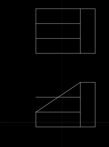
Step 9 : trim unwanted lines
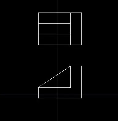
For third figure
Step 10 :copy the rectangle and move left
Step 11: rotate the rectangle
Then move downward
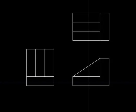
Step 12 : Enter ‘offset’ command
Then specify the distance 0.5
Take offset from upper line
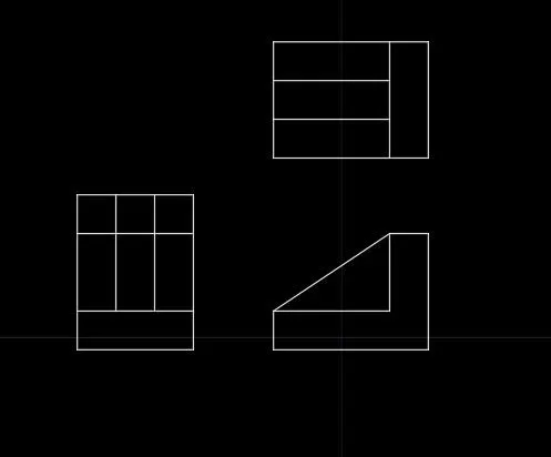
Step 13 :trim unwanted lines using ‘Trim’ command
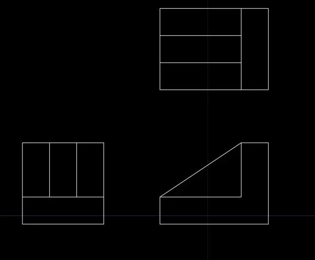
Step 14: Mark dimensions
RESULT
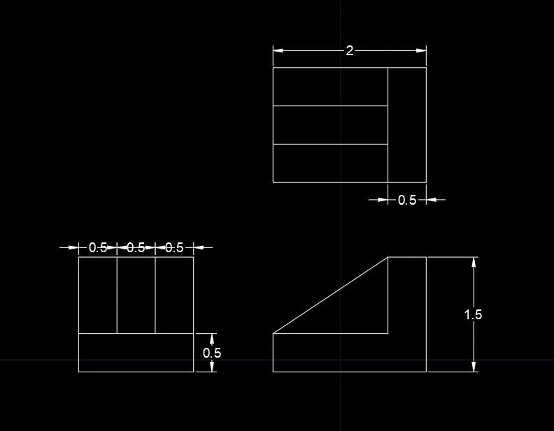
AIM
To create geometry given below
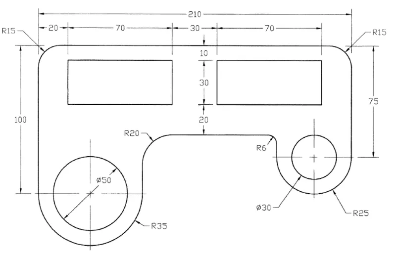
INTRODUCTION
Here we are using line tool,circle, Fillet tool
Direct entry method for drawing the figure
Here we are using unit type as Decimal
PROCEDURE
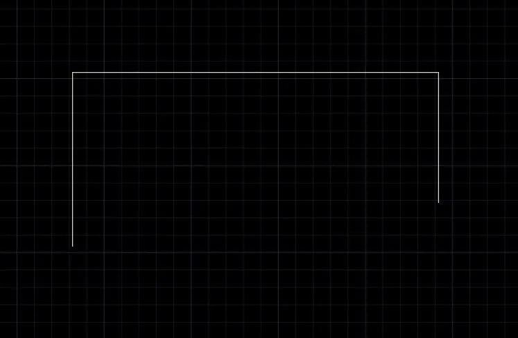
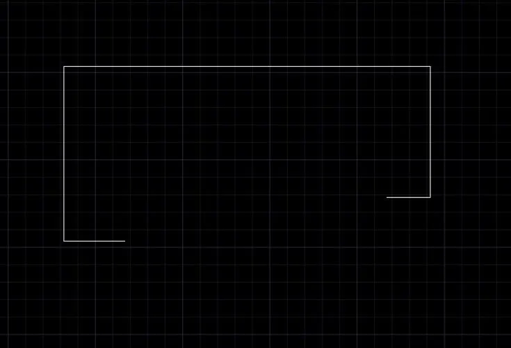
Step 1 : Enter the line command
Specify the first point
Then 100 upward direction
210 towards right
75 downwards
Step 2 : Enter the line command
Specify first point as lower left point
Draw line of 70 unit
Step 3 : Enter the line command
Specify first point as lower right point
Draw line of 50 unit
Step 4 :Enter circle command
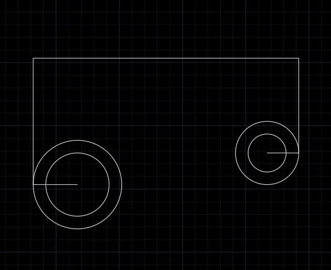
Specify center point as end point on left side
Radius 30 unit
Then enter
Step 5 :Enter circle command
Specify center point as end point on left side
Radius 25 unit
Then enter
Step 6 :Enter circle command
Specify center point as end point on right side
Radius 25 unit
Then enter
Step 7 :Enter circle command
Specify center point as end point on right side
Radius 15 unit
Then enter
Step 8 :Enter ‘offset’ command
Specify distance 70 from left
Then enter
Step 9 :Enter ‘offset’ command
Specify distance 50 from right
Then enter
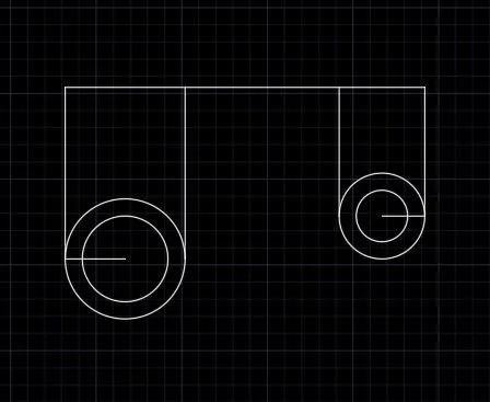
Step 10 :Trim unwanted lines and upper portion of big circles on both side
Enter offset command
specify distance 60 (from upper line)
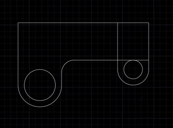
Step 11 : Then enter ‘FILLET’ command
Click on radius
Enter the value 20
click on the lines of left side
Step 12 : Then enter ‘FILLET’ command
Click on radius
Enter the value 6
click on the lines of right side
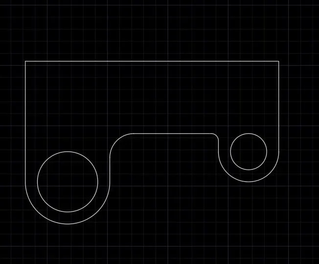
Step 13:Enter rectangle command
Specify first point as the upper left side of the figure
Click on dimensions
Enter length 70
Width 30
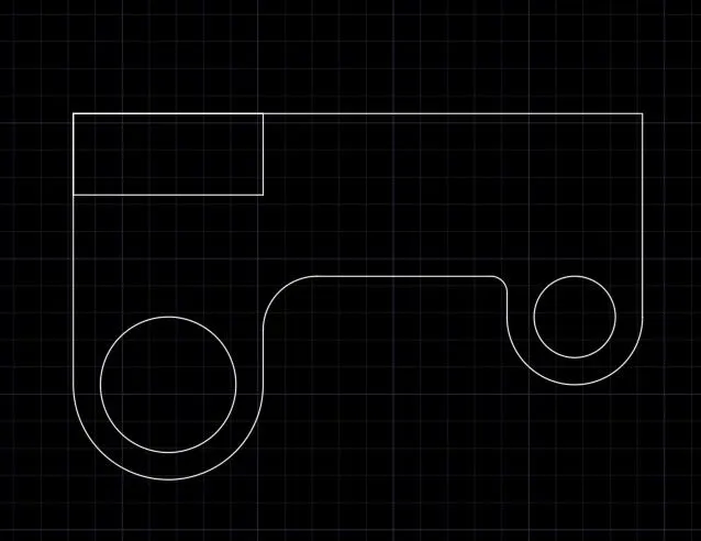
Step 14 : move the rectangle 20 left and 10 downwards
Step 15 : copy the rectangle and move 100 towards right
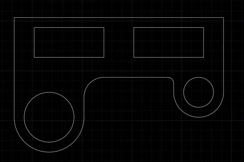
Step 16 : Then enter ‘FILLET’ command
Click on radius
Enter the value 15
click on the lines of left side
Step 17 : Then enter ‘FILLET’ command
Click on radius
Enter the value 15
click on the lines of right side
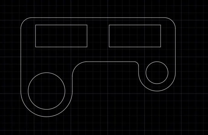
Step 18 : Mark dimensions
RESULT
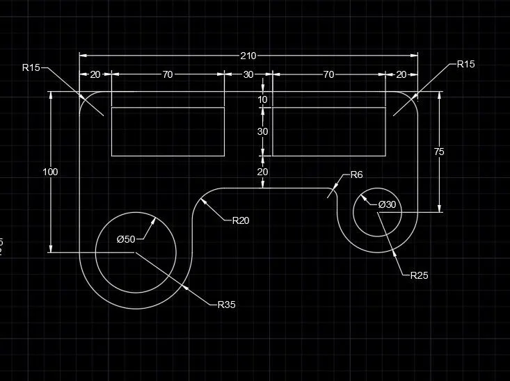
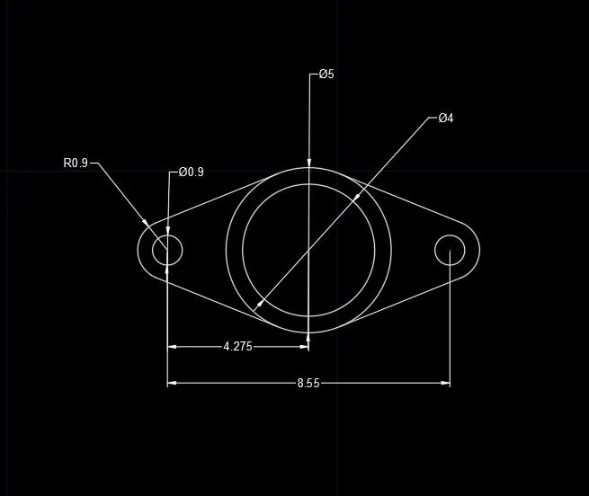
AIM
To create geometry given below
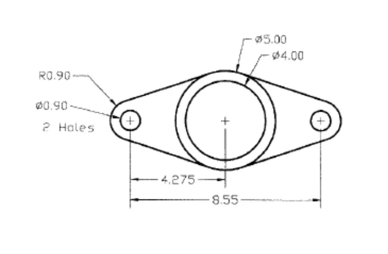
INTRODUCTION
Here we are using line tool,circle, Fillet tool
Direct entry method for drawing the figure
Here we are using unit type as Decimal
PROCEDURE
Step 1 :Enter the circle command
Specify the first point
Click on diameter
Enter the diameter as 4
Step 2 :Enter the circle command
Specify the same first point
Click on diameter
Enter the diameter as 5
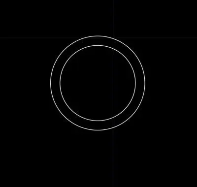
Step 3:Enter line command
Specify first point as the center of circle
Enter 4.275 towards left
Step 4:Enter line command
Specify first point as the center of circle
Enter 4.275 towards right
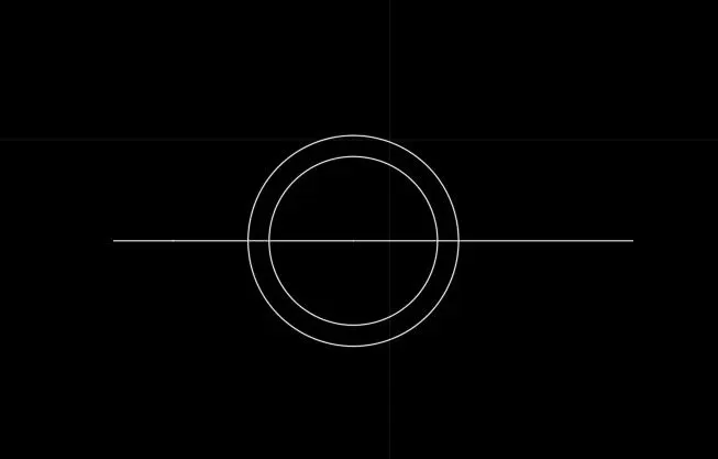
Step 5:Enter circle command
Specify first point as the end point of line on left side
Click on diameter
Enter the vale .9
Step 6:Enter circle command
Specify first point as the end point of line on left side
Click on diameter
Enter the vale 1.8
Step 7:Enter circle command
Specify first point as the end point of line on right side
Click on diameter
Enter the vale .9
Step 8:Enter circle command
Specify first point as the end point of line on right side
Click on diameter
Enter the vale 1.8
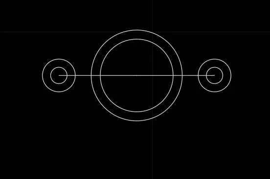
Step 9 :Enter line command
Then SHIFT+right click
Select tangent
Select circle
again SHIFT+right click
Select tangent
Select circle
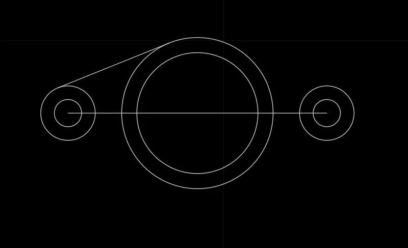
Step 10 :Enter mirror command
Select the tangent line
Select the center of circle to mirror to right side
Then select no
Then Enter
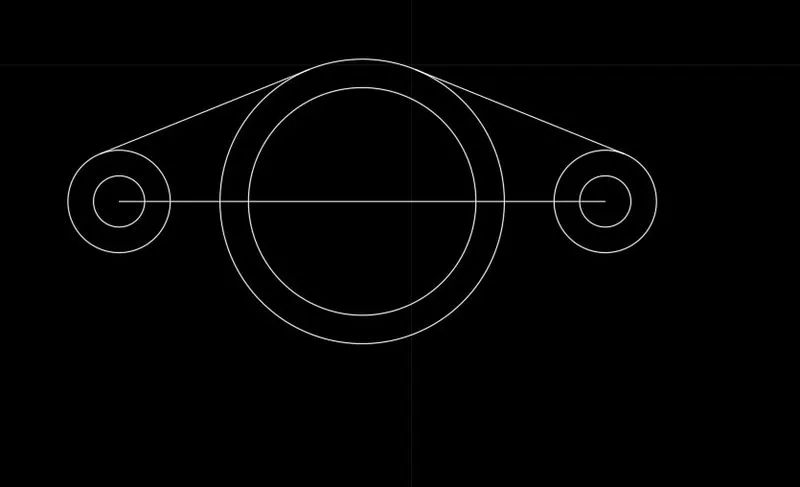
Step 11 :Enter mirror command
Select the two tangent line
Select the center of circle to mirror to downside
Then select no
Then Enter
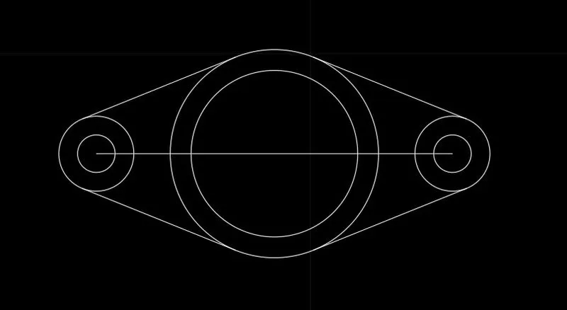
Step 12 :Then trim unwanted lines and circle portions
Mark dimensions
RESULT
AIM
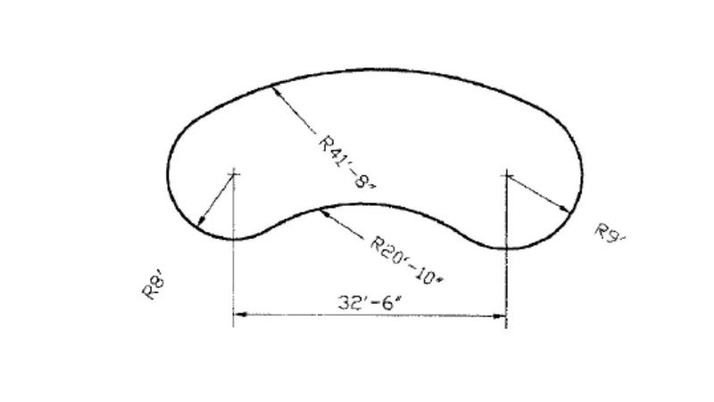
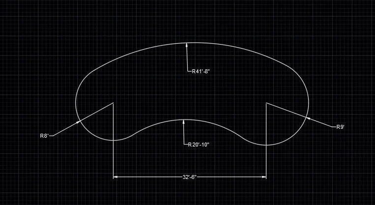
To create geometry given below
INTRODUCTION
Here we are using line tool,circle, Fillet tool
Direct entry method for drawing the figure
Here we are using unit type as Architectural
PROCEDURE
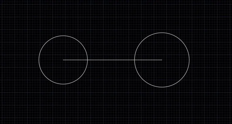
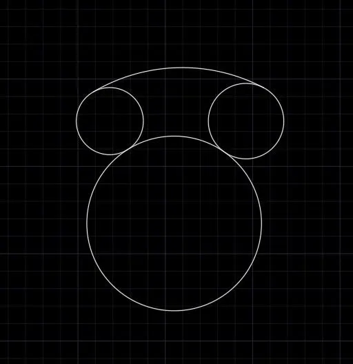
Step 1 : Enter ‘line’ command
Specify first point
Enter the value 32’6”
Step 2 : Enter circle command
Specify first point as the left end of the line
Enter the value 8’
Step 3 : Enter circle command
Specify first point as the right end of the line
Enter the value 9’
Step 4: Enter circle command
Enter ‘ttr’ command
Select the first circle
Then select second circle
Then enter the radius 41’8”
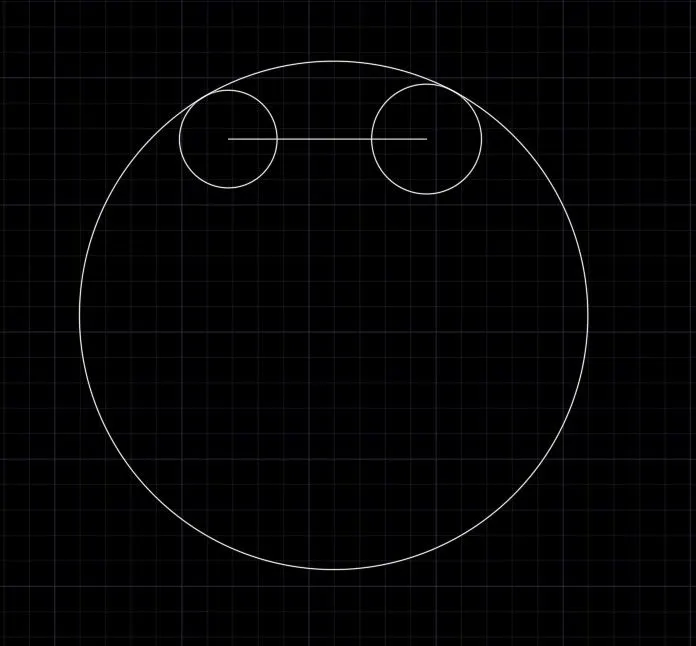
Step 5 :Trim unwanted lines
Step 6 :Enter circle command
Enter ‘ttr’ command
Select the first circle
Then select second circle
Then enter the radius 20’10”
Step 7 :Trim unwanted lines
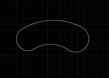
Mark dimensions
RESULT
AIM
To create geometry given below
INTRODUCTION
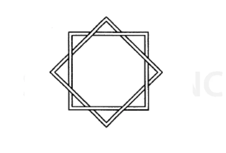
Here we are using line tool,offset tool,Trim
Direct entry method for drawing the figure
Here we are using unit type as Decimal
PROCEDURE
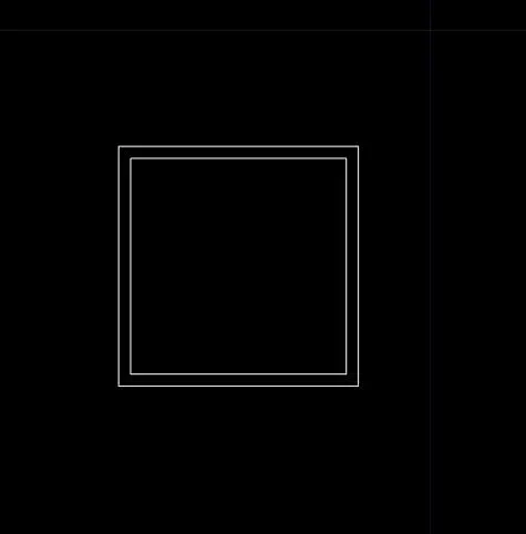
Step 1:Enter the rectangle command
Specify first point
Click on dimensions
Enter the length 4
Width 4
Step 2 : Enter offset command
Specify distance as .2
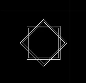
Step 3: Select the rectangles
Enter rotation command
Select copy
Enter the angle for rotation 45
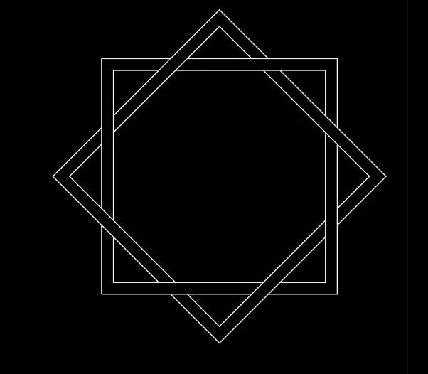
Step 4 : Enter trim command
Trim unwanted lines
RESULT
AIM
To create geometry given below
INTRODUCTION
Here we are using line tool,offset tool,Trim
Direct entry method for drawing the figure
Here we are using unit type as Architectural
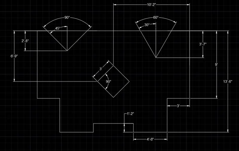
PROCEDURE
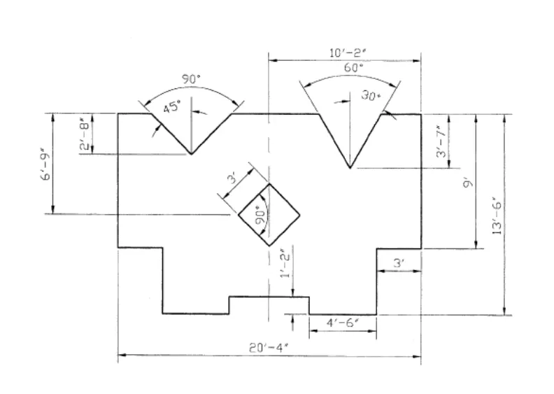
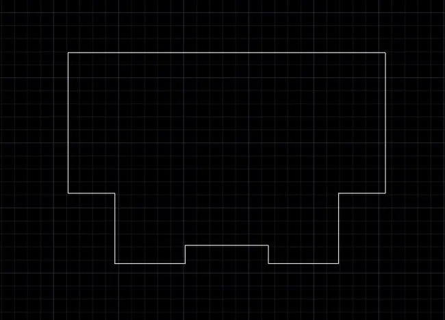
Step 1: Enter the line command
Specify the first point
Then 3’ towards right
4’6” downwards
4’6” towards right
1’2” upwards
5’4” towards right
1’2” downwards
4’6” towards right
4’6” upwards
3’ towards right
9’ upward
20’4” towards left
Then close
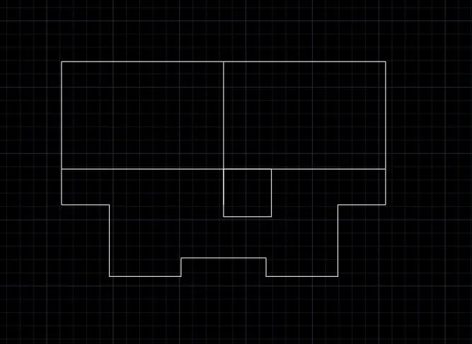
Step 2:Enter the offset command
Specify the distance as 6’9”
Take offset of upper line
Step 3:Enter the offset command
Specify the distance as 10’2”
Take offset of right line
Step 4: Enter rectangle command
Specify first point as the joining point of two offsets
Click on distance
Enter length 3’
Width 3’
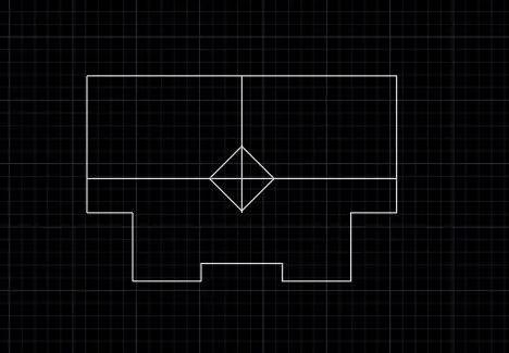
Step 5: Enter rotation command
Select the rectangle
Rotate 45 degree
Step 6:Select the rectangle and move it to the correct place
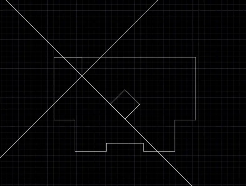
Step 7:Enter line command
Specify first point as the upper left point
Enter the length 4’ towards right
2’8’ downwards
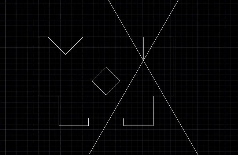
Step 8:Enter ‘XL’
Enter ‘A’
Specify angle 45 degree
Put the line on lower part
Step 9:Enter ‘XL’
Enter ‘A’
Specify angle 135 degree
Put the line on lower part
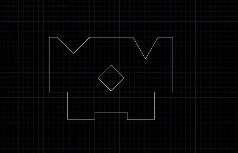
Step 10 :Trim unwanted lines
Step011:Enter line command
Specify first point as the upper right point
Enter the length 4’6” towards right
3’7” downwards
Step 12:Enter ‘XL’
Enter ‘A’
Specify angle 60 degree
Put the line on lower part
Step 13:Enter ‘XL’
Enter ‘A’
Specify angle 120 degree
Put the line on lower part
Step 14 :Trim unwanted lines
Step 15:Mark dimensions
RESULT
RESULT
Here we studied about different kind of tools like
Circle tool
Line tool
Trim
Chamfer
Offset
Construction lines
Fillet
Arc
And different kind of unit settings like
Decimal
Architectural
Engineering etc..