Creating a Floor plan, Footing detail and Isometric view using AutoCad
AIM
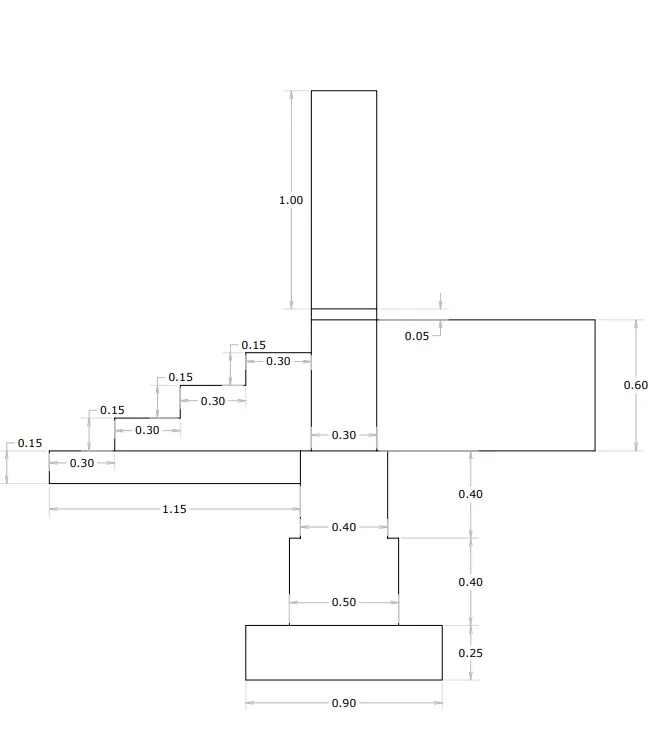
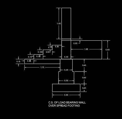
To create cross section of load bearing wall over spread footing
INTRODUCTION
We can using Absolute coordinates method and Direct distance entry method for drawing
And we are using rectangle tool,line tool
In Absolute coordinates method we are providing absolute coordinates of the point for drawing and in the Direct distance entry method we provide the distance and direction for drawing
PROCEDURE
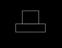
Step 1 :enter ‘REC’ command to draw rectangle
Specify the first point
Then click on dimension
Then provide length 0.9 and width 0.25

Step 2: enter ‘REC’ command to draw rectangle
Specify the first point on the upper edge of first rectangle
Then click on dimension
Then provide length 0.5 and width 0.4
Move the rectangle 0.2 towards right
Step 3: enter ‘REC’ command to draw rectangle
Specify the first point on the upper edge of second rectangle
Then click on dimension
Then provide length 0.4 and width 0.4
Move the rectangle 0.05 towards right
Step 4: enter ‘REC’ command to draw rectangle
Specify the first point on the upper edge of third rectangle
Then click on dimension
Then provide length 0.3 and width 0.65
Move the rectangle 0.05 towards right
Step 4: enter ‘REC’ command to draw rectangle
Specify the first point on the upper edge of fourth rectangle
Then click on dimension
Then provide length 0.3 and width 1
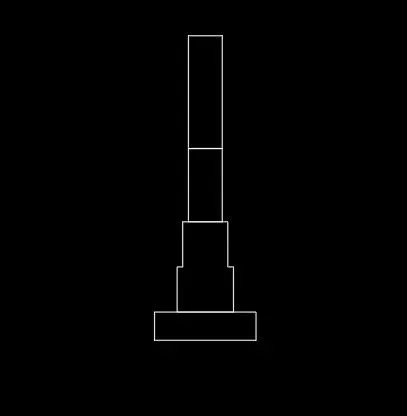
Step 5 :Trim unwanted lines using trim tool
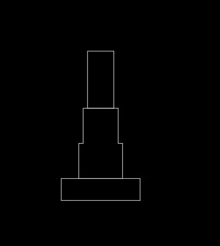
Step 6 :Step 4: enter ‘REC’ command to draw rectangle
Specify the first point on the upper edge of third rectangle towards left
Then click on dimension
Then provide length 1.15 and width 0.15
Move the rectangle downwards
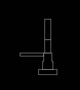
Step 6 : Using line tool draw line of 0.3 from upper left side of fifth rectangle towards right
Stap 7: using direct entry method draw line
.15 upward
.3 towards right
.15 upward
.3 towards right
.15 upward
.3 towards right
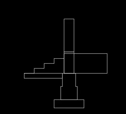
Step 8 :mark dimensions
RESULT
AIM
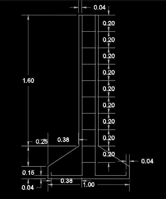
To create cross section of isolated footing
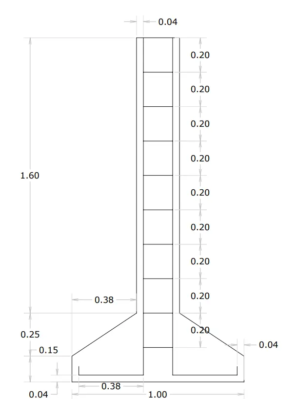
INTRODUCTION
We can using Absolute coordinates method and Direct distance entry method for drawing
And we are using rectangle tool,line tool,CHAMFER ,trim etc..
In Absolute coordinates method we are providing absolute coordinates of the point for drawing and in the Direct distance entry method we provide the distance and direction for drawing
PROCEDURE
Step 1 :enter ‘REC’ command to draw rectangle
Specify the first point
Then click on dimension
Then provide length 1 and width 0.4

Step 2 : Enter the Chamfer Command : CHAMFER
Then click on distance
Then provide first chamfer distance .25
Then provide second chamfer distance ..38
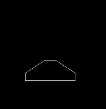
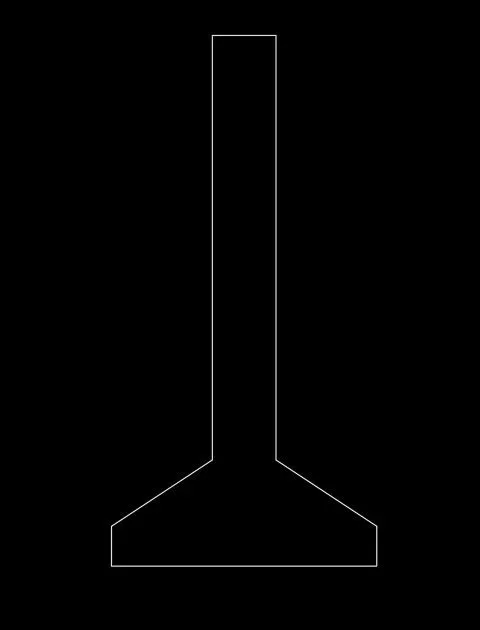
Step 3 :enter ‘REC’ command to draw rectangle
Specify the first point on upper flat side of rectangle
Then click on dimension
Then provide length .24 and width 1.6
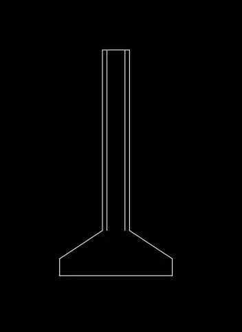
Step 4 :Enter offset command
Provide offset distance of 0.04 from both long side of upper rectangle
Step 5 : using line tool draw line
0.36 downward from the line
0.38 towards left
0.04 towards up
Step 6 : using line tool draw line
0.36 downward from second the line
0.38 towards right
0.04 towards up
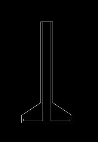
Step 7 :select the upper line of second rectangle
Enter offset command
Then enter ‘a’
Then specify number of offset as 9
Then specify distance as 0.20
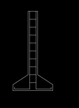
Step 8 : then mark dimensions
RESULT
AIM
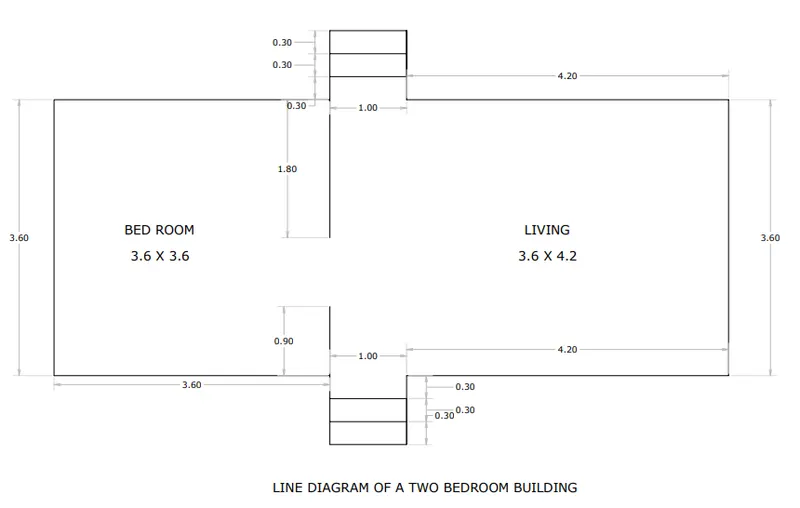
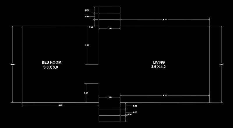
To create line diagram of two bedroom building
INTRODUCTION
We can using Absolute coordinates method and Direct distance entry method for drawing
And we are using rectangle tool,line tool
In Absolute coordinates method we are providing absolute coordinates of the point for drawing and in the Direct distance entry method we provide the distance and direction for drawing
PROCEDURE
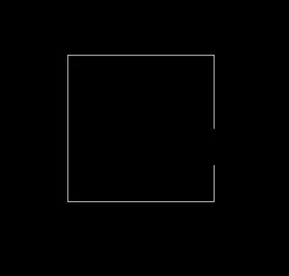
Step 1 :Enter the line command
Draw line 1.8 upwards
3.6 towards left
3.6 downward
3.6 towards right
.9 towards up
Step 2 : draw line from upper right side of the drawing
.9 upwards
1 towards right
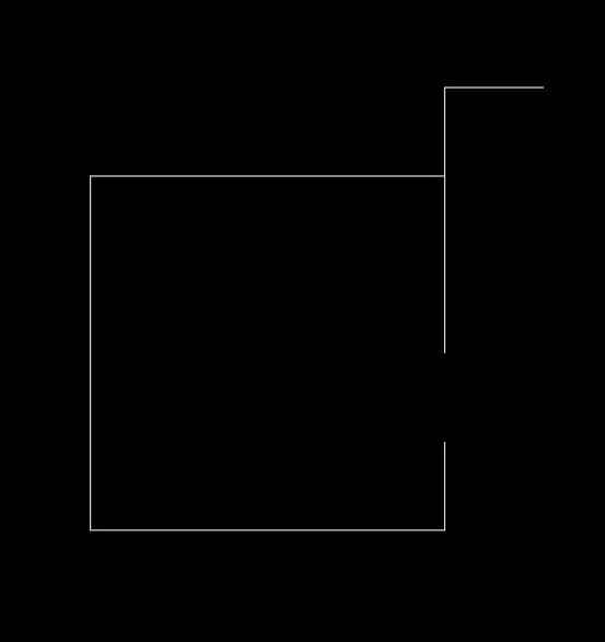
Step 3 : enter offset command
Specify distance .3
Make another offset of .3

Step 4: using line command start a line from the end of drawing
.9 downward
4.2 right
3.6 downward
4.2 left
.9 downward
1 left
.9 upward
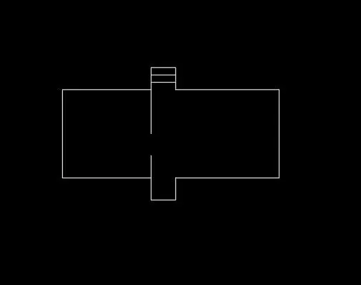
Step 5 : Enter offset command
Enter offset distance of .3
Take one more offset of .3
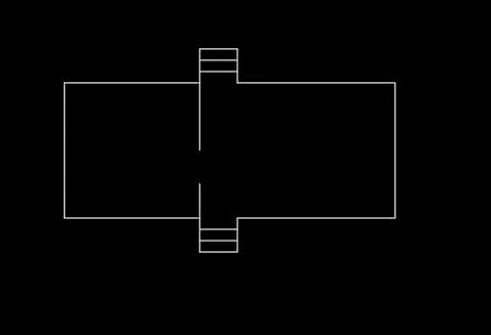
Step 6 : Mark the dimensions
RESULT
AIM
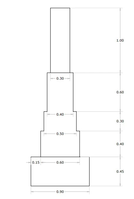
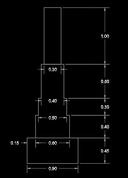
To create cross section of load bearing wall showing foundation details
INTRODUCTION
We can using Absolute coordinates method and Direct distance entry method for drawing
And we are using rectangle tool,line tool
In Absolute coordinates method we are providing absolute coordinates of the point for drawing and in the Direct distance entry method we provide the distance and direction for drawing
Step 1 :enter ‘REC’ command to draw rectangle
Specify the first point
Then click on dimension
Then provide length 0.9 and width 0.45

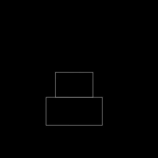
Step 2: enter ‘REC’ command to draw rectangle
Specify the first point on the upper edge of first rectangle
Then click on dimension
Then provide length 0.5 and width 0.4
Move the rectangle 0.2 towards right
Step 3: enter ‘REC’ command to draw rectangle
Specify the first point on the upper edge of second rectangle
Then click on dimension
Then provide length 0.4 and width 0.3
Move the rectangle 0.05 towards right
Step 4: enter ‘REC’ command to draw rectangle
Specify the first point on the upper edge of third rectangle
Then click on dimension
Then provide length 0.3 and width 0.60
Move the rectangle 0.05 towards right
Step 5: enter ‘REC’ command to draw rectangle
Specify the first point on the upper edge of third rectangle
Then click on dimension
Then provide length 0.3 and width 1
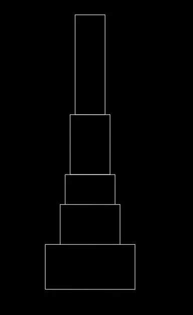
Step 6: Using trim tool trim unwanted lines
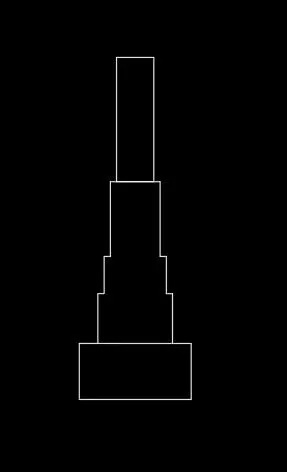
Step 7 : mark the dimensions
RESULT
AIM
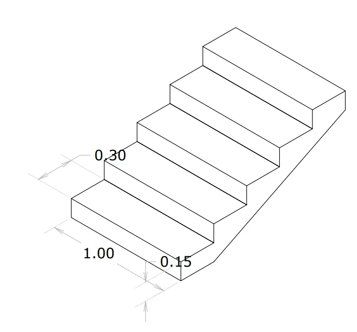
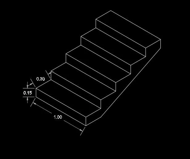
To create isometric view of STEPS
INTRODUCTION
Here we are drawing isometric drwaing using studied tools
Isometric drawings are the drawings which are inclined 30 degree to x axis
There are three ISOMETRIC planes they are
ISOPLANE TOP
ISOPLANE LEFT
ISOPLANE RIGHT
We can using Direct distance entry method for drawing
In Direct distance entry method we provide the distance and direction for drawing
And we are using rectangle tool,line tool
PROCEDURE
Step 1 : Enter the isodraft command ‘ISODRAFT’
Select ISOPLANE LEFT
Enter line command
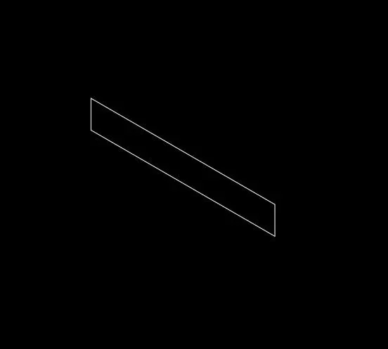
Step 2 : using line tool draw line
1 towards right
0.15 towards up
1 towards left
0.15 downward
Step 3 :select ISOPLANETOP(using F5 key)
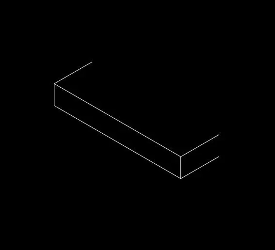
Using line tool draw line on upper right corner
0.3 towards right
Enter copy command
Paste copy on the left side
Paste copy on the lower right side
Step 4 : select ISOPLANE LEFT
Select all the lines except lower right line
Copy using COPY command
Paste it on the corners of the step
Paste 3 more copies on the every corner side
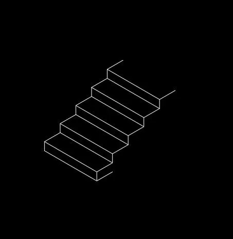
Step 5: select ISOPLANE LEFT
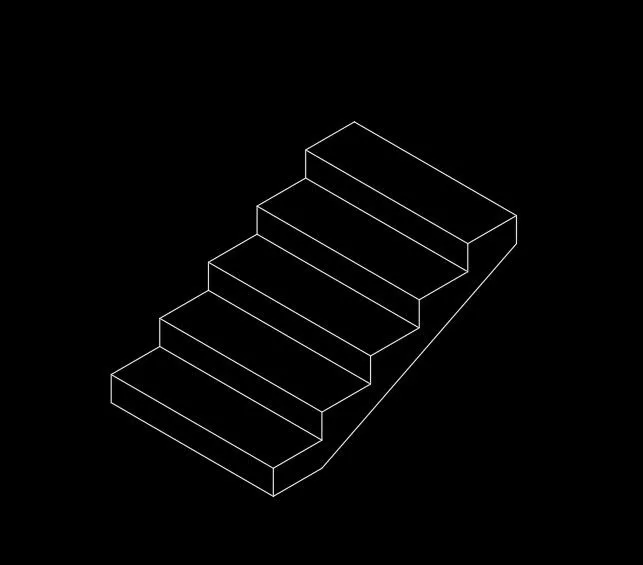
Using line command draw line on last step
1 towards right
0.15 downward
Close the step
Step 6 : mark dimensions
RESULT
AIM
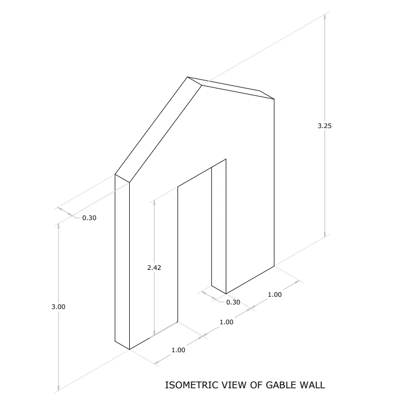
To create isometric view of GABLE WALL
INTRODUCTION
Here we are drawing isometric drwaing using studied tools
Isometric drawings are the drawings which are inclined 30 degree to x axis
There are three ISOMETRIC planes they are
ISOPLANE TOP
ISOPLANE LEFT
ISOPLANE RIGHT
We can using Direct distance entry method for drawing
In Direct distance entry method we provide the distance and direction for drawing
And we are using rectangle tool,line tool
PROCEDURE
Step 1 : Enter the isodraft command ‘ISODRAFT’
Select ISOPLANE LEFT
Enter line command
Step 2 : Select ISOPLANE LEFT
Enter line command
0.3 towards right
3 towards up
0.3 towards left
3 downward
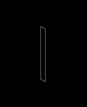
Step 3 : select ISOPLANE RIGHT
Enter line command
Specify first point on the lower right side
1 towards right
2.42 upwards
1 towards right
2.42 downwards
1 towards right
3 upwards
3 towards left
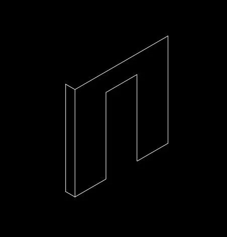
Step 4: Enter line command
1 m upward from the center of the line
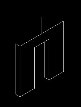
Step 5: select ISOPLANE LEFT
Draw line on upper side of the line
0.3 towards right
Draw line on left side
0.3 towards right
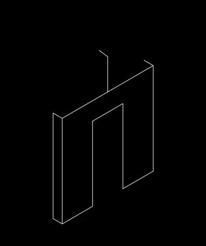
Step 6: off the ORTHOMODE
Enter the line command
Draw lines connecting the sides step
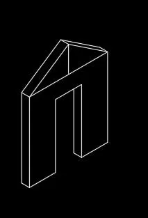
Step 7 : Using trim tools trim unwanted lines
RESULT
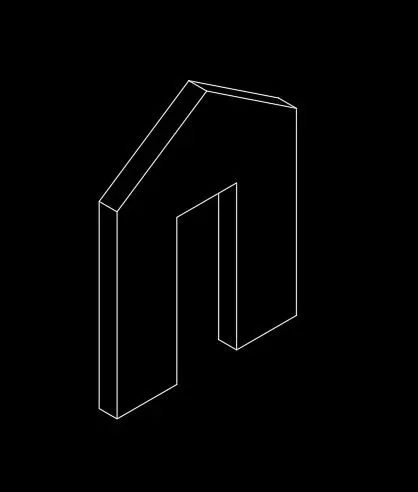
RESULT
Here we studied about ISOMETRIC drawings and other 2D drawings
Studied about the Direct method of drawing