Creating a Residence Layout, Seating plan, Toilet and Utility room plan using AutoCad
1.Residence Plan:
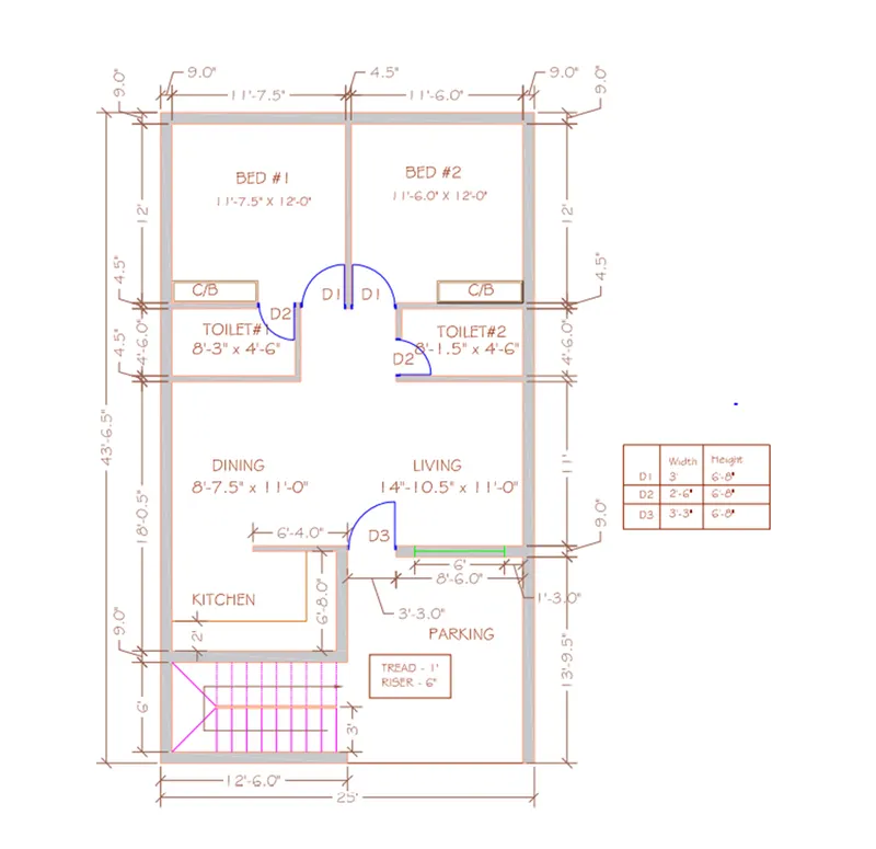
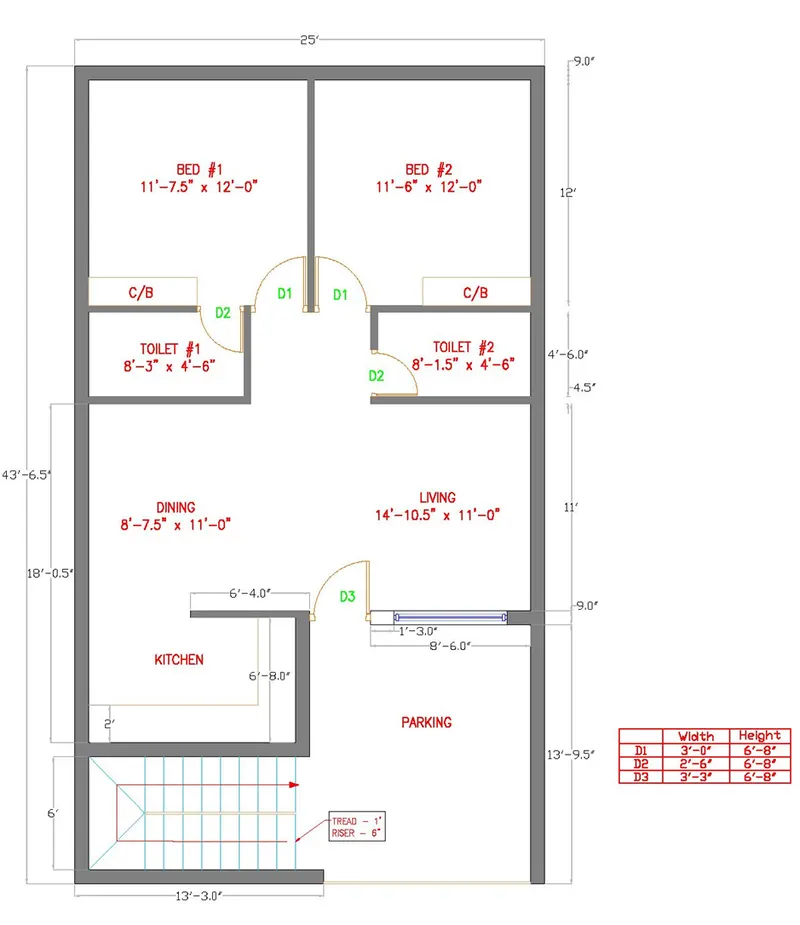
Aim: To draw the layout of a residence as shown in the figure using AutoCAD
Introduction: The Residential plan is created by using draw tolls and modify tools in AutoCAD. The procedure followed to draw is explained in detail with diagrams of each step and the final result is given.
|
Procedure: Step 1 Type unit or UN in the command line and press enter Set type of unit as Engineering and precision as 0’- 0.0” Set the limits by typing LIM specify the left corner points and right corner points Type Z in command line press enter then A to zoom. Step 2 From layer property in Home tab create new layer for text, dimension, interior walls, exterior walls, doors, windows, stairs, hatch and furnitures.
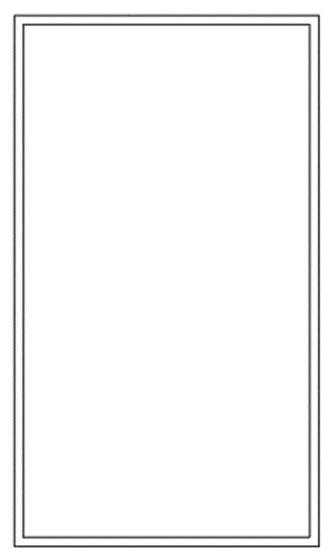
Step 3 Type REC in the command line then press enter to invoke rectangle tool Specify the first point on the screen Type D and Press Enter to specify dimension of rectangle Specify rectangle length 43’ 6.5” then Enter Specify rectangle width 25’ |
 |
|
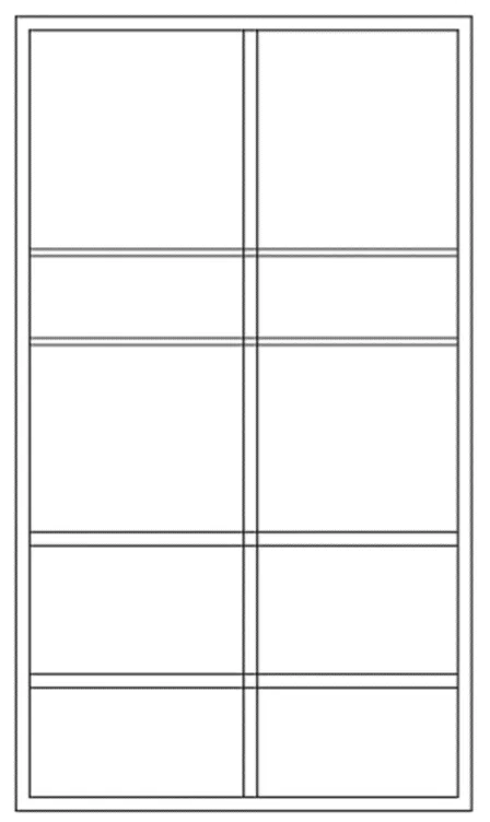
Step 4 Type offset or O in the command box and press enter Specify offset distance 9” by typing in command line then press Enter Step 5 Type X in the command box to explode Select the objects Step 6 Type offset or O in the command box and press enter Enter the offset distance then press enter Offset the lines to get respective room dimensions |
 |
|
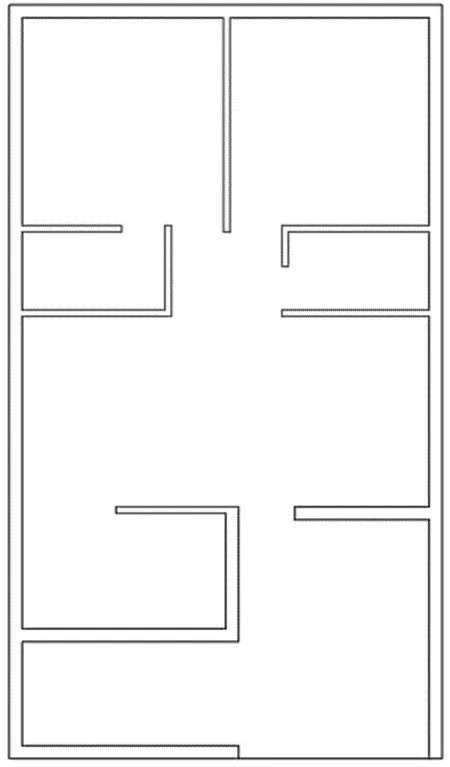
Step 7 Type TR in the command line to invoke trim tool Select the object which needs to be trimmed |
 |
|
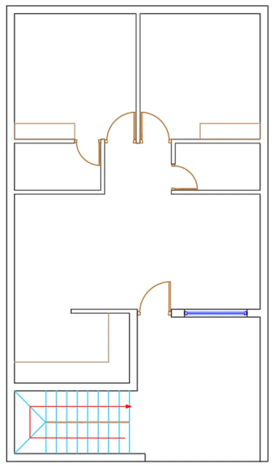
Step 8 Draw stairs using line command and offset command then doors, windows, kitchen slab and cupboard using line command, rectangle command and arc command. Step 9 Type hatch in the command box and press enter Select solid hatch and wall internal part Type DIM in the command box and press enter to measure the dimensions Add required dimensions to drawing Type TEXT in the command box and press enter Add titles on drawing with room dimension |
 |
RESULT
The given Residential plan is drawn using line, rectangle, fillet, offset, trim, hatch, dimension tool and text tool in AutoCAD.
2.Seating plan for an outdoor canopy:
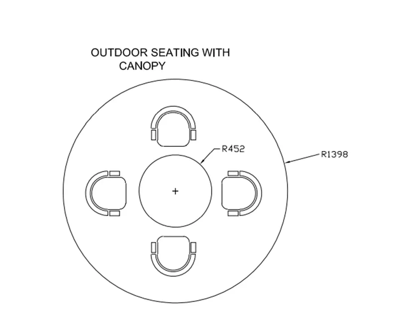
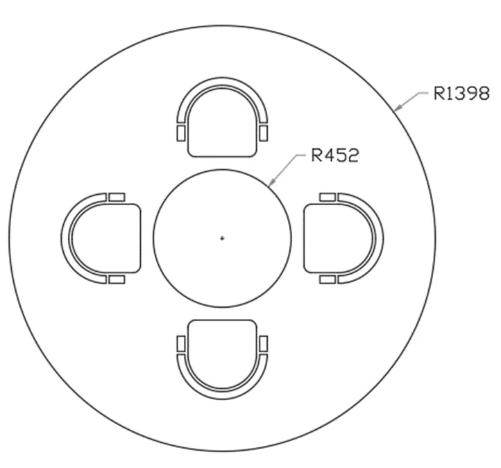
Aim: To draw outdoor seating with canopy as shown in the figure using AutoCAD
Introduction: The given outdoor seating canopy is created by using draw tolls and modify tools in AutoCAD. The procedure followed to draw is explained in detail with diagrams of each step and the final result is given. The Dimensions for seating are assumed as appropriate. Also, all the dimensions are considered in Decimal type.
|
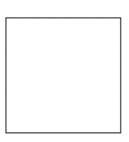
Procedure: Step 1 Type unit or UN in the command line and press enter Set type of unit as Decimal and precision as 0 Step 2 Type REC in the command line and press enter Specify the dimensions as 450 length and 450 width |
 |
|
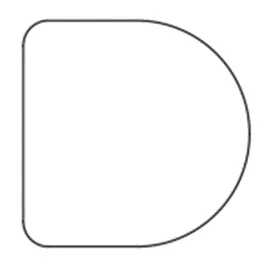
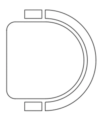
Step 3 Type FIL in the command line to invoke the fillet tool Specify the radius 50 then select the edges Again, change the fillet radius to 225 then select the objects on right side |
 |
|
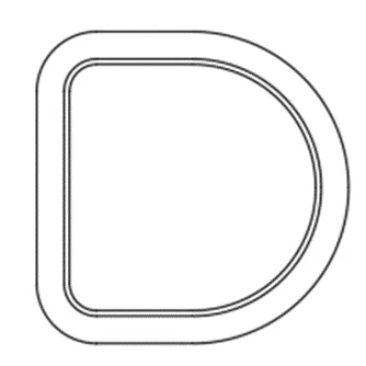
Step 4 Type O in the command line and press enter Specify offset distance 20 Select object to offset Then again specify the offset distance as 50 then select the outer object |
 |
|
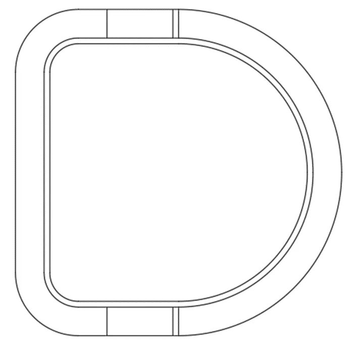
Step 5 Type L in the command line and press enter Draw the line where ever required |
 |
|
Step 6 Type TR in the command line and press enter Select the object which needs to be trimmed to get required sketch |
 |
|
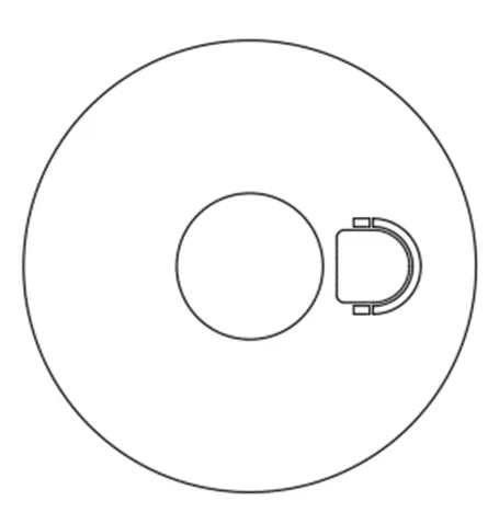
Step 7 Type C in the command line to invoke circle tool Specify center point for circle Specify radius of circle as 452 and press enter Again, invoke the circle tool Specify center same center point for circle Specify radius of circle as 1398 and press enter Type M to invoke move tool Select the object then move it inside the circle Step 8 Select polar array from the modify tools from home panel Specify the center Specify the number of items as 4 and press enter Type DIMRAD in the command box and press enter Add required dimensions to drawing |
 |
RESULT
The given outdoor seating canopy is created by using draw tolls such as line, rectangle, circle and modify tools such as trim, fillet and dimension tools in AutoCAD.
3.Plan for the toilers and utilities room:
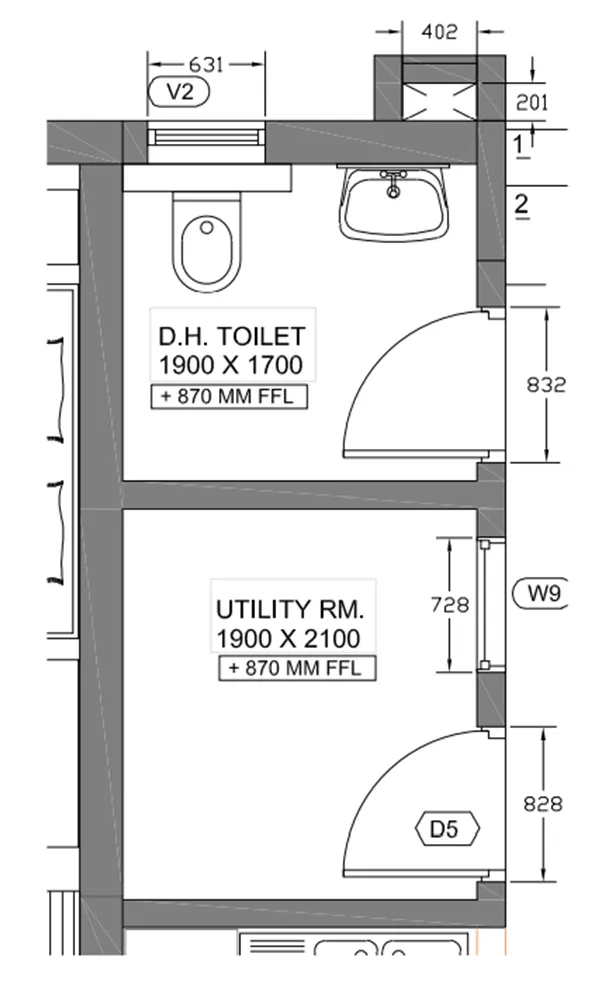
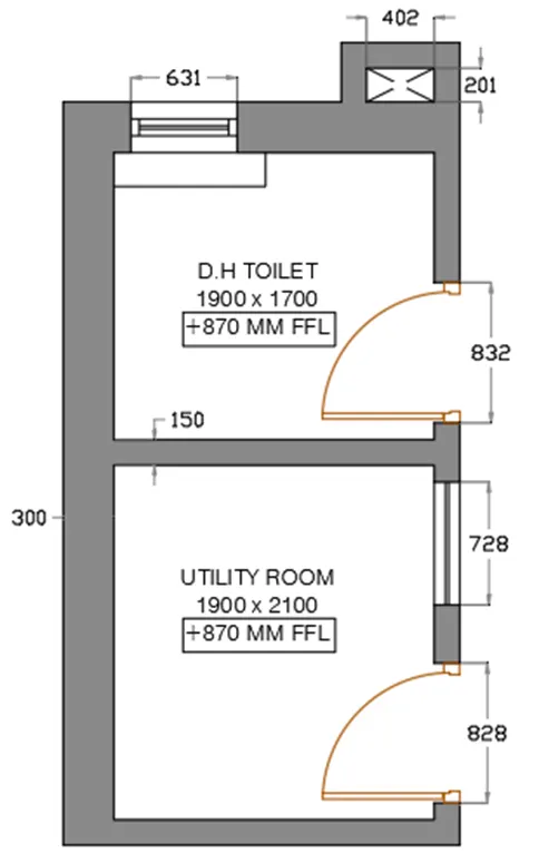
Aim: To draw the plan for the toilers and utilities room as shown in the figure using AutoCAD
Introduction: The given plan for the toilers and utilities room is created by using draw tolls and modify tools in AutoCAD. The procedure followed to draw is explained in detail with diagrams of each step and the final result is given. The outer wall thickness is taken as 300 mm and inner wall thickness as 150 mm. The missing dimensions are assumed.
|
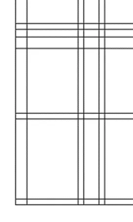
Procedure: Step 1 Type unit or UN in the command line and press enter Set type of unit as Decimal and precision as 0 Step 2 Press F8 or turn on ortho mode from the status bar Type RAY in the command line and press enter Draw the horizontal and vertical lines Type OFF in the command line and press enter Specify the offset distance for outer wall as 300 and for inner wall 150 Offset the lines to get the respective room dimension |
 |
|
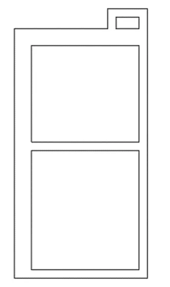
Step 3 Type TR in the command line to invoke trim tool Select the object which needs to be trimmed |
 |
|
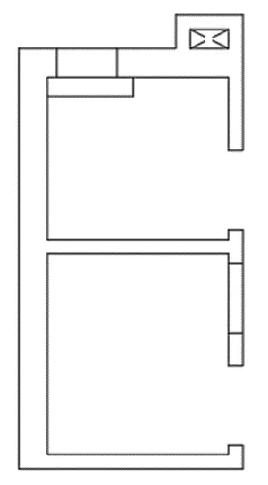
Step 4 Type L in the command line to involve the line tool Draw the lines to create windows and doors and trim the extra lines Step 5 Hatch the wall with solid hatch Type DIM in the command box and press enter Add required dimensions to drawing |
 |
RESULT
The given plan of toilers and utilities room is created by using draw tolls such as line, rectangle, circle and modify tools such as trim and dimension tools in AutoCAD.