Drafting of various geometries using Chamfer, Fillet tool in AutoCad
Drafting of various geometries using Chamfer, Fillet tool in AutoCad
aim:
to create the geomentry using some of the tools
Tools which are used for this diagram is
line,
circle
polar
etc
procedure:
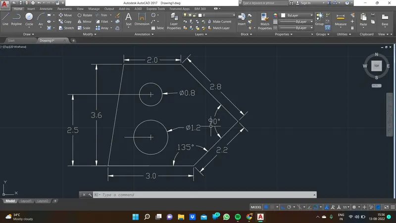
first line has been taken and draw the first point 3(length)
next @ of 2.2 <45 has drew
next @of 2.8<45 has drew
next 2 whereas close (enter) to finish the drawing ..
draw the circle at a distance of 1 which is length of y axis and 1.50 which is a x axis dist to draw the circle with diameter 1.2 and upper circle could be drew at adist of 2.5 depth with 1.50 x direction
result:
aim :
to create the geomentry using various tools
tools used :
line tool
polar mode
procedure:
draw 2'5" line belong that @3'<45 has drew
and again @2'6"<45 has drew and ther first line along with the horiz line which is 6' and along
1'9" draw vertical line and draw @1'5"<315 and the close enter to finish the drawing
result :
s
aim :
to draw the geomentry using some of tool in cadd
tools used
line
circle
polar
procedure:
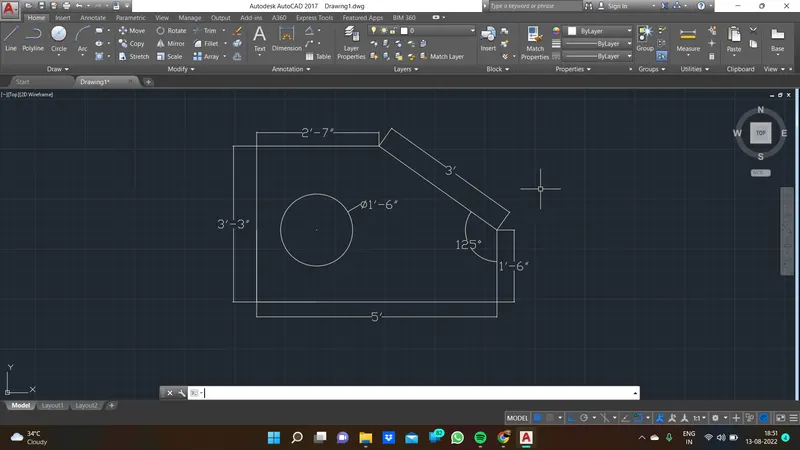
draw 3'3" vert line and along eith 5' of haori line has drew and 1'6" draw vertically belong that @3'<125
close enter to finish the drawing to obtain the last length is 2'7"
result:
aim:
to draw the geomentry using tools
tools using
lines
procedure:
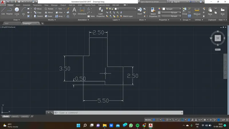
draw the line 3.50 vertically , upward horizon dist is 2.50
draw the line just your wish vertically again 2.50 is depth of line for right side down
result
aim:
to draw the geomentry using tools
tools we used:
line
circle in dia
offset
mirror
procedure:
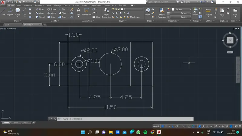
first draw the horizontal line for 11.5 and draw left the vert line is 6.0 and 3 height and 1.5 width to draw circle @ a dia of 2 and inner circle has 1 dia and centre of the circle is mark and we could start the line to right side which length is 4.25 to draw another circle beside of the two hole circle which is 3 dia and finally finish of these we would use mirror to get other side because each side has same dimension so that is why we use ,mirror...
result:
aim :
to draw the geomentry using tools
tools we used:
line
offset
procedure:
draw the line 0.50 and do offset as same value to finish
result

aim :
to draw the geomentry using tools
tools :
line
fillet
trim
circle in dia
circle in rad
procedure:
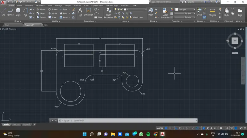
`draw line tool dim is 100 vert and along that 210 is upper horiz line has drew and 60 dwn of line is drew
draw dia of 50, and here same pt radius also draw with 35 r and other side dia of circle 25 and rad 35
use fillet in upper line left and right with rad is 15
down also use fillent in that circle along line fillet is used r20 and r 6 is used
resultL:
aim :
to draw the geomentry using tools
tools :
line
mirror
trim
circle in dia
circle in rad
procedure :
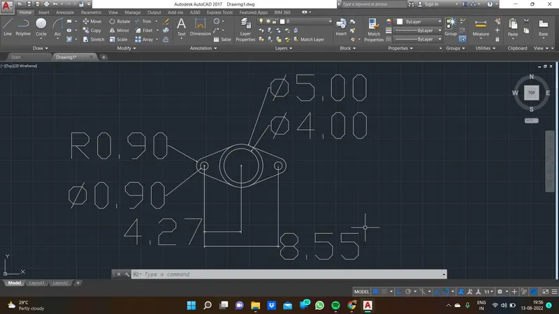
draw circle @ dia 5 and inner dia 4
left side of dist4.27 to draw dia 0.9 circle it surroud byradius 90 circle and join the tangent line to join two circle
and trim unnecessary circle lines
and then mirror tool is used get the other side
result:
aim :
to draw the geomentry using tools
tools :
line
copy
trim
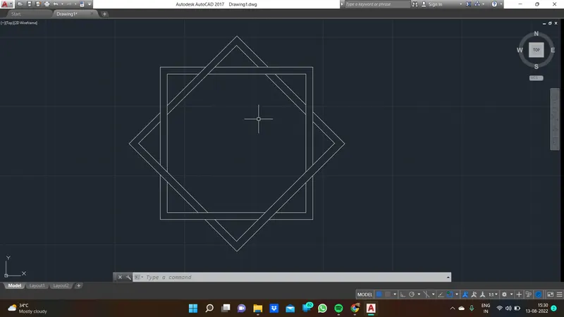
procedure : just draw the line in our prefered dim and draw the perfect square and copy the square place over the copied square and one square is seems like <45 to trim unnecessary line to get this
result;
aim :
to draw the geomentry using tools
tools :
line
trim
circle in dia
circle in radr
procedure:
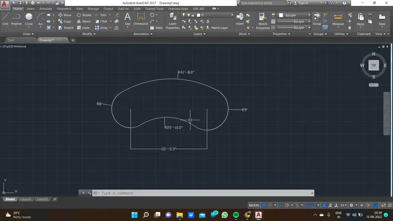
draw circle r8' and opp side circle r9'
use tan tan radius between both circle upper and lower for upper 41'
and remain 20' and trim unnecessary circle over lap lines
result: