Drafting of various geometries using Chamfer, Fillet tool in AutoCad
Aim:
To draft the various geometries using the tools in AutoCAD.
Procedure:
Sketch-1:
- The dimensions are measured for the sketch are.
- Units = Decimal
- Angle = Decimal degrees
- Angle measured = East
- Angle direction = Anti-clockwise
- Area = (x, y)
- We can modify the units in Ribbon > Home > Annotations.
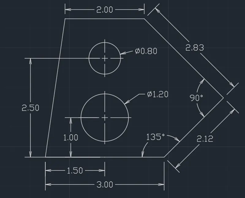
- First, we take the base point as (0,0).
- At first, we complete the boarder of the sketch with coordinate system or direct distance entry method and with using angles.
- We take the line tool or polyline tool to create the sketch. For Line tool we select from the Command as LINE.
- After select the line tool we give the points or coordinates of the lines to complete the boarder with use of angles.
- After completion of boarder, then we use the circle tool from the Command as CIRCLE.
- Select the circle tool with (centre, diameter) option and complete the drawing of two circles.
- After completion of the sketch, we can use the Command as DIMLIN to measure as per the required dimensions.
Sketch-2:
- The dimensions are measured for the sketch are
- Units = Architectural
- Angle = Decimal degrees
- Angle measured = East
- Angle direction = Anti-clockwise
- Area = (x, y)
- We can modify the units in Ribbon > Home > Annotations.
- In architectural units 1unit = 1 inch
- We give the points as per the requirements.
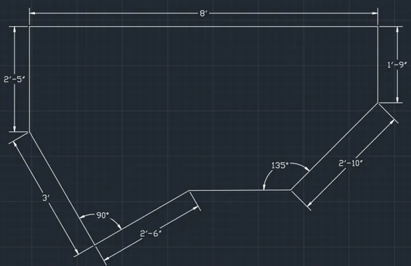
- First, we take the base point as (0,0).
- At first, we complete the boarder of the sketch with coordinate system or direct distance entry method and with using angles.
- We take the line tool or polyline tool to create the sketch. For Line tool we select from the Command as LINE.
- After select the line tool we give the points or coordinates of the lines to complete the boarder with use of angles.
- After completion of the sketch, we can use the Command as DIMLIN to measure as per the required dimensions.
Sketch-3:
- The dimensions are measured for the sketch are
- Units = Engineering
- Angle = Decimal degrees
- Angle measured = East
- Angle direction = Anti-clockwise
- Area = (x, y)
- We can modify the units in Ribbon > Home > Annotations.
- In engineering units 1unit = 1 inch
- We give the points as per the requirements.
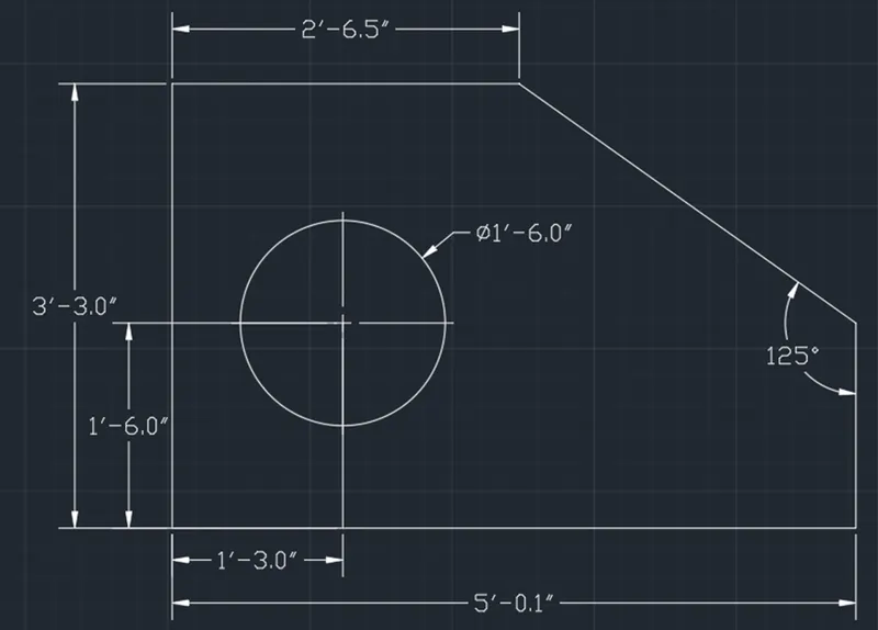
- First, we take the base point as (0,0).
- At first, we complete the boarder of the sketch with coordinate system or direct distance entry method and with using angles.
- We take the line tool or polyline tool to create the sketch. For Line tool we select from the Command as LINE.
- After select the line tool we give the points or coordinates of the lines to complete the boarder with use of angles.
- After completion of boarder, then we use the circle tool from the Command as CIRCLE.
- Select the circle tool with (centre, diameter) option and complete the drawing of the circle.
- After completion of the sketch, we can use the Command as DIMLIN to measure as per the required dimensions.
Sketch-4:
- The dimensions are measured for the sketch are.
- Units = Decimal
- Angle = Decimal degrees
- Angle measured = East
- Angle direction = Anti-clockwise
- Area = (x, y)
- We can modify the units in Ribbon > Home > Annotations.
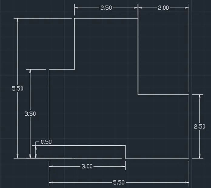
- First, we take the base point as (0,0).
- At first, we complete the boarder of the sketch with coordinate system or direct distance entry method.
- We take the line tool or polyline tool to create the sketch. For polyline tool we select from the Command as PLINE.
- After select the polyline tool we give the points or coordinates of the lines to complete the boarder.
- After completion of the sketch, we can use the Command as DIMLIN to measure as per the required dimensions.
Sketch-5:
- The dimensions are measured for the sketch are.
- Units = Decimal
- Angle = Decimal degrees
- Angle measured = East
- Angle direction = Anti-clockwise
- Area = (x, y)
- We can modify the units in Ribbon > Home > Annotations.
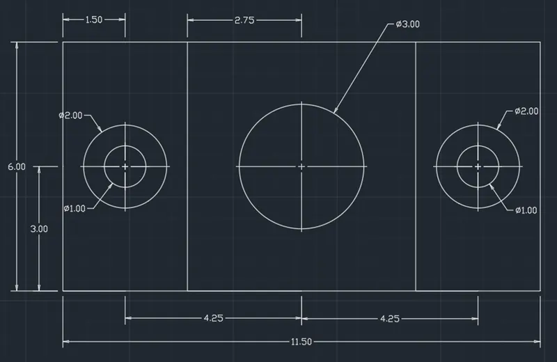
- First, we take the base point as (0,0).
- At first, we complete the boarder of the sketch with coordinate system or direct distance entry method.
- We take the line tool or polyline tool to create the sketch. For Line tool we select from the Command as LINE.
- After select the line tool we give the points or coordinates of the lines to complete the boarder.
- After completion of boarder, then we use the circle tool from the Command as CIRCLE.
- Select the circle tool with (centre, diameter) option and complete the drawing of five circles.
- After completion of the sketch, we can use the Command as DIMLIN to measure as per the required dimensions.
Sketch-6:
- The dimensions are measured for the sketch are.
- Units = Decimal
- Angle = Decimal degrees
- Angle measured = East
- Angle direction = Anti-clockwise
- Area = (x, y)
- We can modify the units in Ribbon > Home > Annotations.
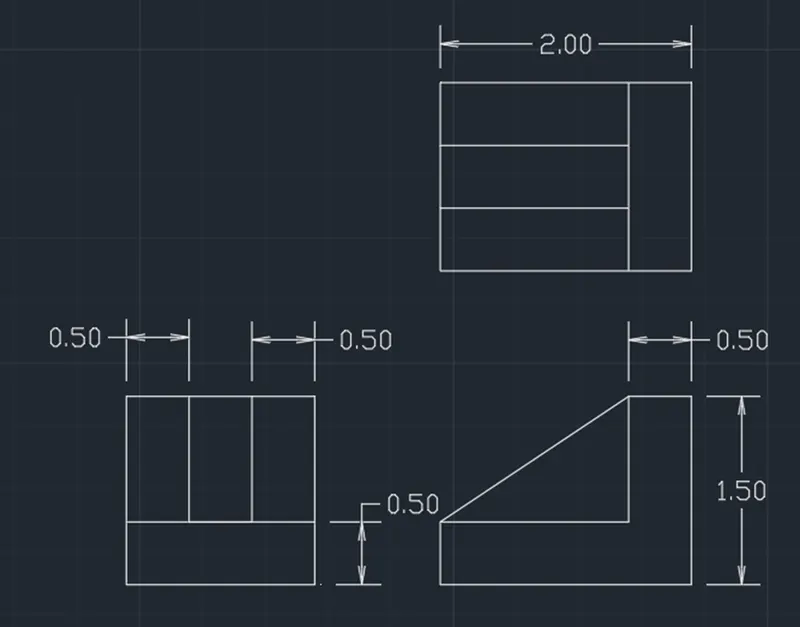
- First, we take the base point as (0,0).
- At first, we complete the boarder of the sketch with coordinate system or direct distance entry method.
- We take the line tool or polyline tool to create the sketch. For Line tool we select from the Command as LINE.
- After select the line tool we give the points or coordinates of the lines to complete the boarders of three sketches.
- The distance between the lines inside the boarder is 0.5 units.
- After completion of the sketch, we can use the Command as DIMLIN to measure as per the required dimensions.
Sketch-7:
- The dimensions are measured for the sketch are.
- Units = Decimal
- Angle = Decimal degrees
- Angle measured = East
- Angle direction = Anti-clockwise
- Area = (x, y)
- We can modify the units in Ribbon > Home > Annotations.
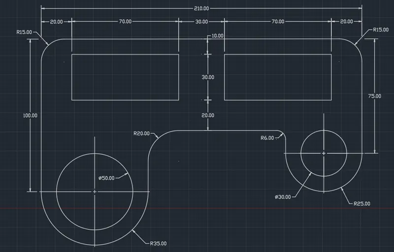
- First, we take the base point as (0,0).
- At first, we complete the boarder of the sketch with coordinate system or direct distance entry method.
- We take the line tool or polyline tool to create the sketch. For Line tool we select from the Command as LINE.
- After select the line tool we give the points or coordinates of the lines to complete the boarder and rectangles inside the boarder.
- For completion of the boarder, we use arc tool the Command as
- Select the arc tool with (start, end, radius) option and complete the drawing of two arcs.
- We use the circle tool from the Command as CIRCLE.
- Select the circle tool with (centre, diameter) option and complete the drawing of two circles.
- After completion of circles, we draw the curves at the corners of the boarder, so we use the command as FILLET.
- Select the fillet tool and give the points as radius to complete the curves at the corners.
- After completion of the sketch, we can use the Command as DIMLIN to measure as per the required dimensions.
Sketch-8:
- The dimensions are measured for the sketch are.
- Units = Decimal
- Angle = Decimal degrees
- Angle measured = East
- Angle direction = Anti-clockwise
- Area = (x, y)
- We can modify the units in Ribbon > Home > Annotations.
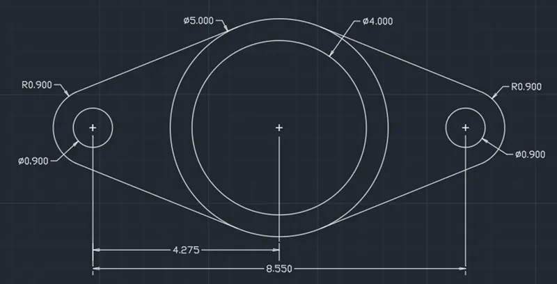
- First, we take the base point as (0,0).
- At first, we complete the boarder of the sketch with coordinate system or direct distance entry method.
- We place points at particular distance using Command POINT and place three points at different specified coordinates.
- we use the circle tool from the Command as CIRCLE.
- Select the circle tool with (centre, diameter) option and complete the drawing of six circles at different points as per specified coordinates.
- After that we use circle tool again with (tan, tan, radius) option and complete the drawing of two circles in North and South directions w.r.t the outer circles of East side and also at West
- Then mark the intersection points with OSNAP
- Then connect the intersection points on four sides.
- Then we use the Command TRIM and complete the sketch as per the requirements.
- After completion of the sketch, we can use the Command as DIMLIN to measure as per the required dimensions.
Sketch-9:
- The dimensions are measured for the sketch are.
- Units = Architectural
- Angle = Decimal degrees
- Angle measured = East
- Angle direction = Anti-clockwise
- Area = (x, y)
- We can modify the units in Ribbon > Home > Annotations.
- In architectural units 1unit = 1 inch
- We give the points as per the requirements.
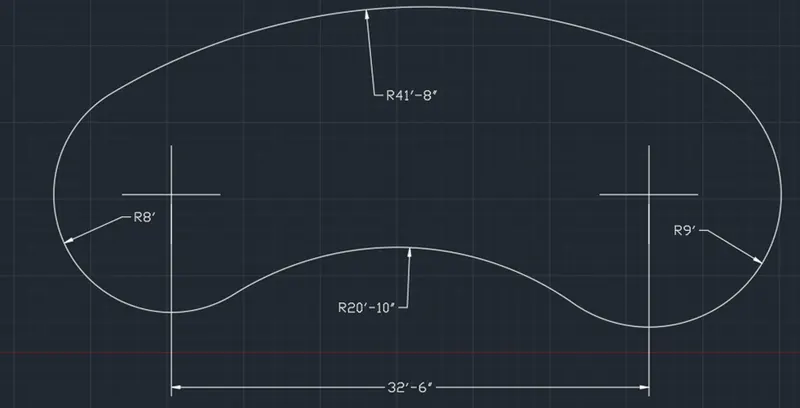
- First, we take the base point as (0,0).
- At first, we complete the boarder of the sketch with coordinate system or direct distance entry method.
- We place points at particular distance using Command POINT and place two points.
- we use the circle tool from the Command as CIRCLE.
- Select the circle tool with (centre, diameter) option and complete the drawing of two circles at two different points.
- After that we use circle tool with (tan, tan, radius) option and complete the drawing of two circles in North and South directions w.r.t the circle we drawn first.
- Then mark the intersection points with OSNAP
- Then we use the Command TRIM and complete the sketch as per the requirements.
- After completion of the sketch, we can use the Command as DIMLIN to measure as per the required dimensions.
Sketch-10:
- The dimensions are measured for the sketch are.
- Units = Decimal
- Angle = Decimal degrees
- Angle measured = East
- Angle direction = Anti-clockwise
- Area = (x, y)
- We can modify the units in Ribbon > Home > Annotations.
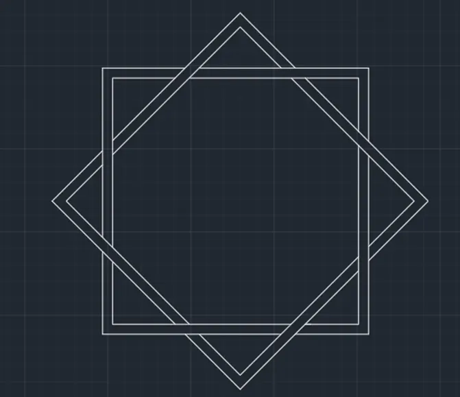
- First, we take the base point as (0,0).
- At first, we complete the boarder of the sketch with coordinate system or direct distance entry method.
- We take the line tool or polyline tool to create the sketch. For Line tool we select from the Command as LINE.
- After select the line tool we give the points or coordinates of the lines to complete the drawing of square.
- The distance between the outside and inside square is 0.3 units.
- Use the Command COPY, then copy the square as second square.
- Use the Command MOVE, and place second square at specified height on the first square.
- Then use the Command ROTATE and rotate the second square with 450.
- Then we use the Command TRIM and complete the sketch as per the requirements.
Sketch-11:
- The dimensions are measured for the sketch are.
- Units = Architectural
- Angle = Decimal degrees
- Angle measured = East
- Angle direction = Anti-clockwise
- Area = (x, y)
- We can modify the units in Ribbon > Home > Annotations.
- In architectural units 1unit = 1 inch
- We give the points as per the requirements.
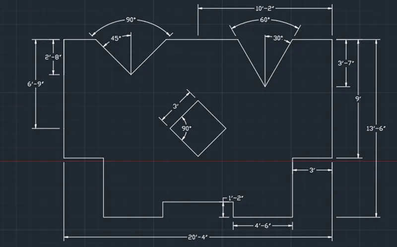
- First, we take the base point as (0,0).
- At first, we complete the boarder of the sketch with coordinate system or direct distance entry method and with using angles.
- We take the line tool or polyline tool to create the sketch. For Line tool we select from the Command as LINE.
- After select the line tool we give the points or coordinates of the lines to complete the boarder.
- We take the line tool again.
- After select the line tool we give the points or coordinates of the lines to complete the drawing of square with specified dimensions separately.
- Use the Command MOVE, and place square at specified height on the first square.
- Then use the Command ROTATE and rotate the second square with 450.
- Take the line tool and draw the middle lines of the two cones w.r.t the specified dimensions.
- Then draw the lines with given angles on the both sides of the middle lines of the two cones.
- Then mark the intersection points with OSNAP
- Then we use the Command TRIM and complete the sketch as per the requirements.
- After completion of the sketch, we can use the Command as DIMLIN to measure as per the required dimensions.
Result:
The above sketches are drawn by using both Absolute and Relative coordinate systems.
The tools used for the completion of the geometries are:
- LINE
- PLINE
- CIRCLE
- ARC
- POINT
- DIMLIN
- MOVE
- COPY
- ROTATE
- FILLET
- TRIM
- ERASE
- OSNAP
Conclusion:
The sketching and drawing in the Auto CAD are drawn by using coordinate systems, as more we practise, we are able to do sketching and drawing fastly and accurately.