Creating a Floor plan, Footing detail and Isometric view using AutoCad
Aim:
To create the sketch for the following geometries by using the coordinates system methods and use the Line tool and isometric drafting to create the geometries.
Procedure:
Cross-section of load bearing wall showing foundation details:
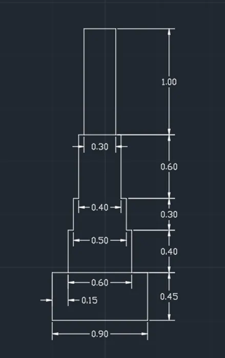
- First, we take the base point as (0,0).
- Then we take the line tool to create the sketch of cross-section of load bearing of the wall.
- The sketch is done by using relative rectangular coordinate system in both X and Y directions.
- After completion of the sketch, we can give the dimensions as per the requirements.
Cross-section of load bearing wall over spread footing:
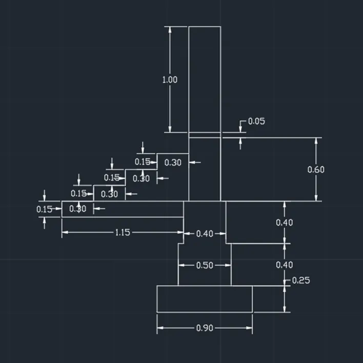
- First, we take the base point as (0,0).
- Then we take the line tool to create the sketch of cross-section of load bearing of the wall over spread footing.
- The sketch is done by using relative rectangular coordinate system in both X and Y directions.
- After completion of the sketch, we can give the dimensions as per the requirements.
Cross-section of isolated footing:
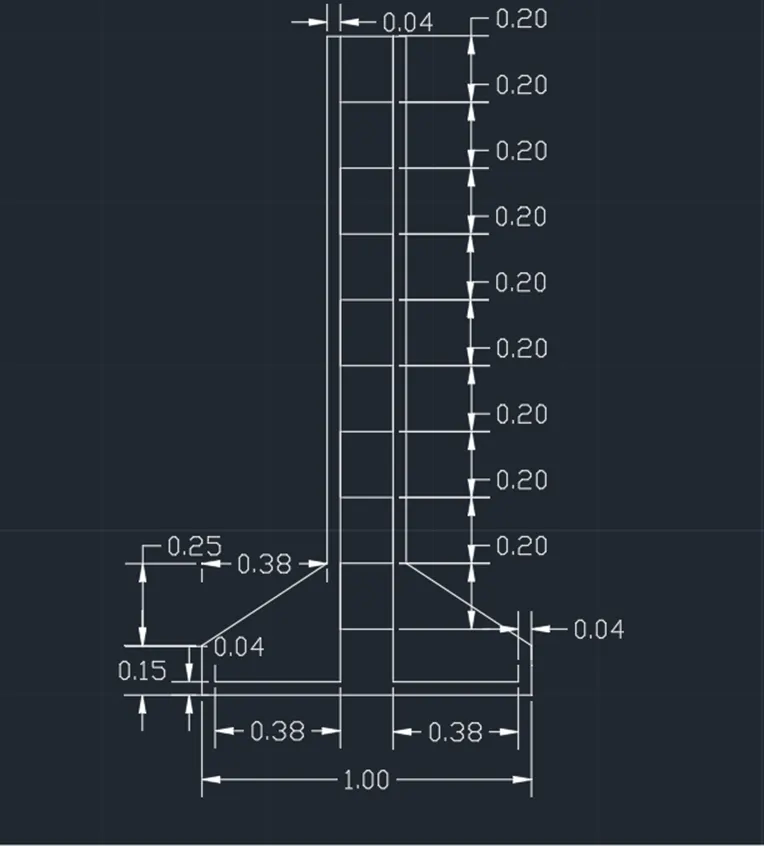
- First, we take the base point as (0,0).
- Then we take the line tool to create the sketch of cross-section of isolated footing.
- The sketch is done by using relative rectangular coordinate system in both X and Y directions.
- After completion of the sketch, we can give the dimensions as per the requirements.
Line diagram of two bed room building:
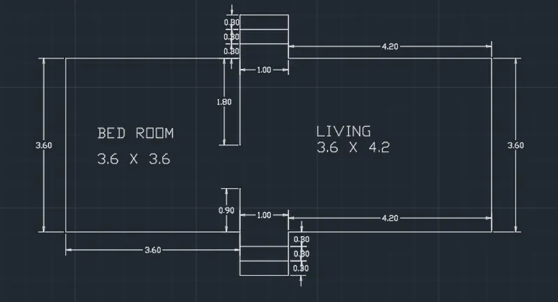
- First, we take the base point as (0,0).
- Then we take the line tool to create the sketch of two bed room building.
- The sketch is done by using relative rectangular coordinate system in both X and Y directions.
- After completion of the sketch, we can give the dimensions as per the requirements.
Isometric view of steps:
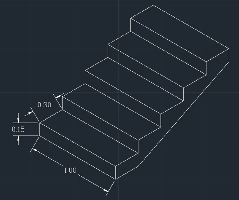
- First, we take the base point as (0,0).
- Then we take the line tool and isolated drafting mode to create the sketch of isometric view of steps.
- The sketch is done by using relative rectangular coordinate system in both X and Y directions.
- After completion of the sketch, we can give the dimensions as per the requirements.
Isometric view of gable wall:
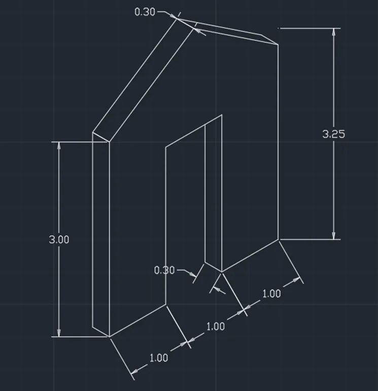
- First, we take the base point as (0,0).
- Then we take the line tool and isometric view mode to create the sketch of isometric view of gable wall.
- The sketch is done by using relative rectangular coordinate system in both X and Y directions.
- After completion of the sketch, we can give the dimensions as per the requirements.
Result:
The above sketches are drawn by using both Absolute and Relative coordinate systems.
Conclusion:
The sketching and drawing in the Auto CAD are drawn by using coordinate systems, as more we practise, we are able to do sketching and drawing fastly and accurately.