Drafting of various geometries using Chamfer, Fillet tool in AutoCad
AIM: To draw the given sketches in autocad using commands.
INTRODUCTION:To know about various commands using autocad like rotate,chamfer,fillet,move,offset etc to ease thr sketching process.
PROCEDURE:
DRAWING 1:
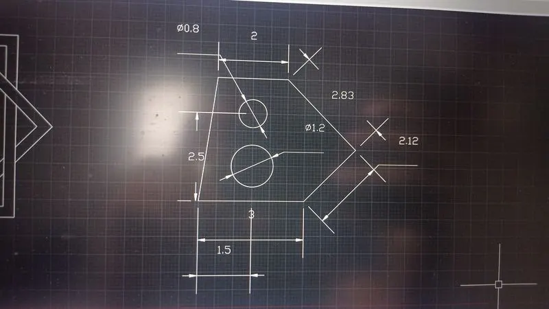
1.Open new file and set decimal and precision to 0.00.
2.Command line: From random point draw 3.00 m line and @2.12<45, @2.83<135 then 2.00m line and close.
3.Command offset:Offset 3.00m line to 1.00m and 2.50m.
4.Command circle:From midpoint of 3.00m line at 2.50m and 1.0Om draw a circle of diameter of 1.20 at 1.00m and 0.80 at 2.50m.
5.Command erase:Erase the offsets.
DRAWING 2:
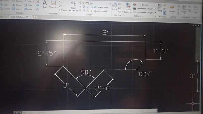
1.New sheet- units- Engineering-precision 0'-0"- feet-ok.
2. Select Line tool and draw the lengths starting from top line segment of 8' , now give line command positioning the cursor at 270 degrees with ortho ON , 1'-9" enter.
3.Give line command positioning the cursor at 270 degrees with ortho ON at first end and draw 2'-5" enter.
4. Draw the line at 315degree of 3', at 90degree 2'-6". Now, draw the line 2'-10" at 225degrees and join the lines.
5.Annotate and give dimension to all the line segments.
DRAWING 3:
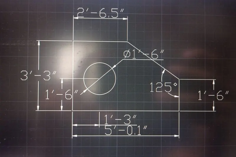
1.New sheet- units- Engineering-precision 0'-0"- feet-ok.
2. Select Line tool and draw the lengths starting from top line segment of 2'-6.5" , now give line command positioning the cursor downwards with ortho ON , 3'-3.0", 5'-0.1",1'-6.0" and close.
3.Annotate and give dimension to all the line segments.
DRAWING 4:
1.New page and select decimals with precision 0.00 while keeping ortho on.
2.Command line:Draw 3.00m line in +ve X axis
3.0.50 In -ve Y axis, 2.50m in +ve X axis, 2.50m in +ve Y axis, 2.00m in -ve X axis, 3.00m in +ve Y axis, 2.50m in -ve X axis, 2.00m in -ve Y axis, 3.00m in -ve Y axis and close.
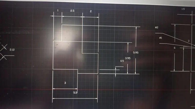
DRAWING 5:
1. Select Line tool and draw the lengths starting from base of 11.50 units , now give line command @6<90, @11.50<180, and close. Draw the vertical lines at 2.75 from the centre of the rectangle on both sides.
2. Draw concentric circles with centre at x=1.50 and y=3.00 of diameter 1.00 and 2.00 . Copy the circles toward 4.25 right from the of the rectangle.
3. Draw another circle at centre of the rectangle of diameter 3.00.
4.Annotate and give dimension to all the line segments and circles.
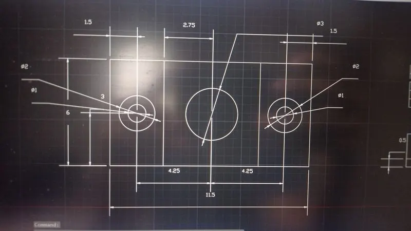
DRAWING 6:
1.New page select decimal with precision 0.0.
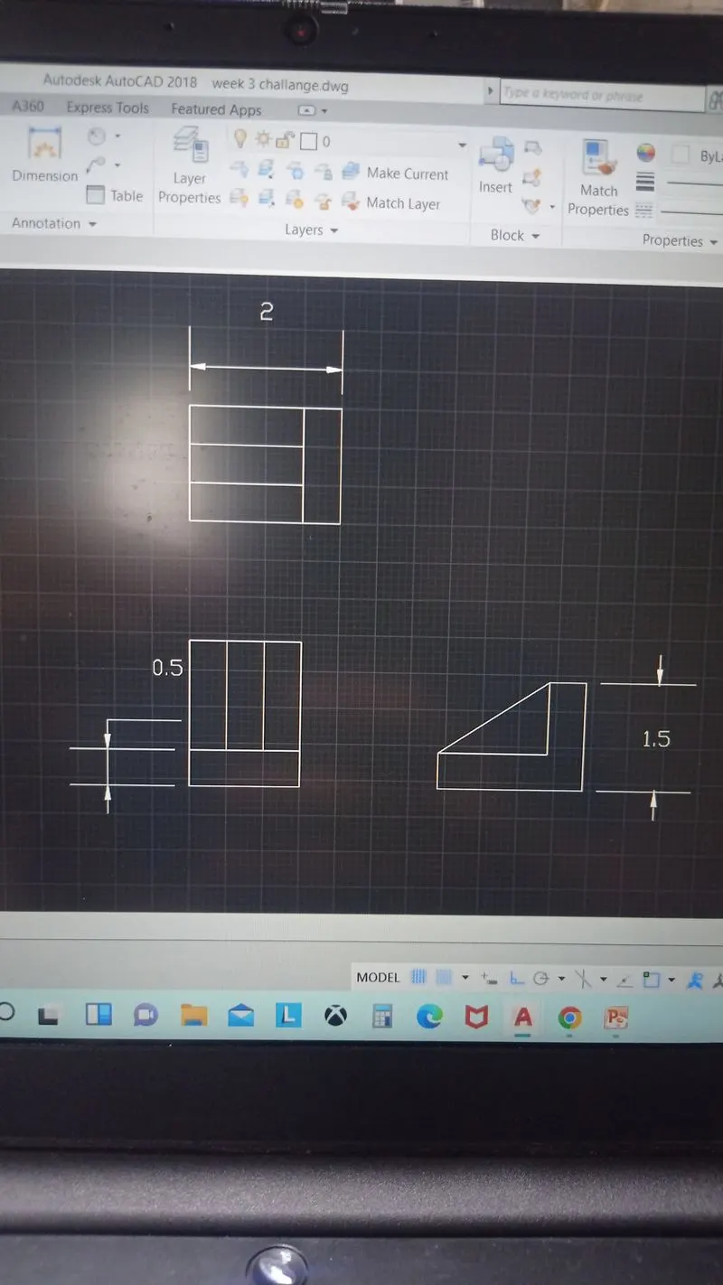
2.Command line:1.Sm horizontal and 1.5m vertical on both sides.
3.Command offset offset 1.5m line to 0.5m.
4.Command divide: Divide 1.5m line into 3 segments.
5.Command line-: Join the divided lines.
6.In object snap setting keep the Extension On
7.Command line: Draw 2.0m line and 1.5m line and O.5m horizontal on top and ln vertical and 1.5m horizontal and O.5m vertical and join the slant line.
8.Command line:2.0m horizontal and 1.5m vertical on both sides.
9.Command offset: offset 1.5m line to O.5m.
10.Command divide: Divide 1.5m line into 3 segments.
11.Command line: Join the divided lines.
DRAWING 7:
1.New sheet- units- decimal-precision 0.0000- meter-ok.
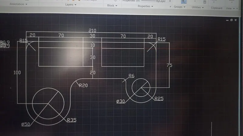
2. Select Line tool and draw the lengths starting from base of 210 units , now give line command @100<270. Draw @75<270. Draw the rectangles 70,30 and copy at distance 30.
3. Draw circles with centre at y=100 and y=75. Draw parallel lines from both the circle and using fillet tool give radius of 35, 20, 6 and 15 .
4.Annotate and give dimension to all the line segments and circles.
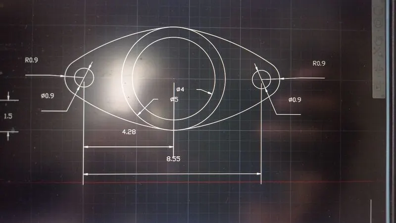
DRAWING 8:
1.New page set decimal and precision to 0.00
2.Command cirde:Draw concentric circles of diameter 5.00m and 4.00m
3.Command line: From the centre point of circle draw 4.275m line on both sides.
4.Command circle: Drawing a circle of diameter 0.90m on both sides.
5.Command arc: from start, end and radius draw an arc of radius 0. 90 on both sides
6.Command line: Join the lines to the arc.
DRAWING 9:
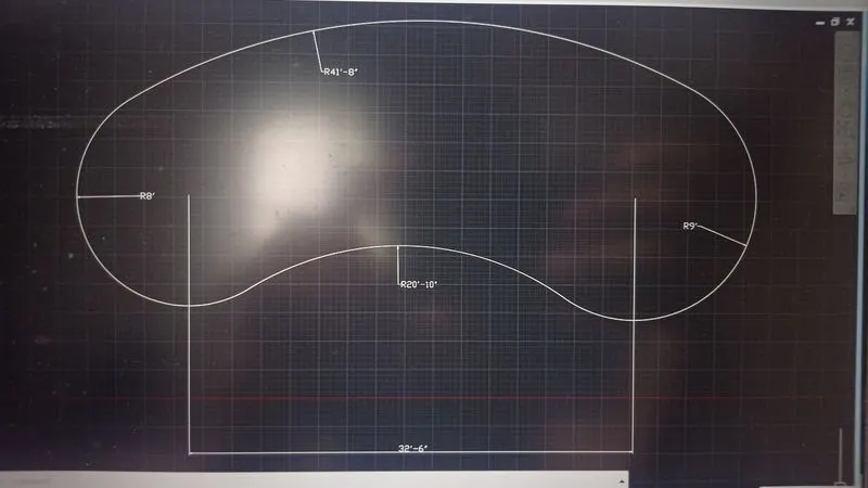
1. Select circle tool and draw the circles of radius 8' and 9' at a centre to centre distance of 32'-6". Using fillet connect the circles with radius 41'-8" and 20'-10".
2.Annotate and give dimension to all the line segments.
DRAWING 10:
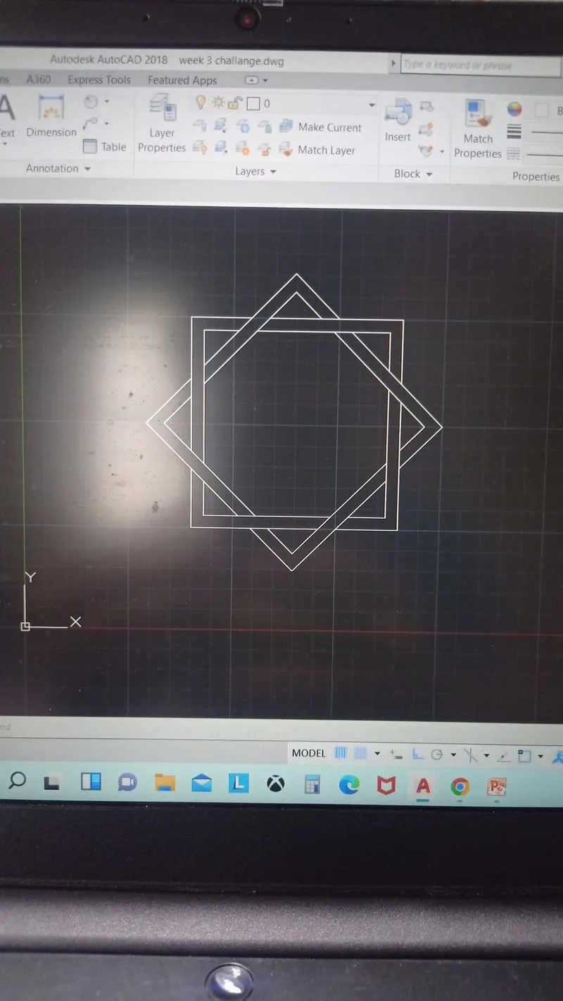
1.Command rectangle: Draw a rectangte of same length and same width of one smaller size and another slightly bigger one from common centre.
2.Command Rotate: Rotating the drawn squares by 45 degree keeping the copy
3.Command trim:Trim the crossing lines according to the figure.
DRAWING 11:
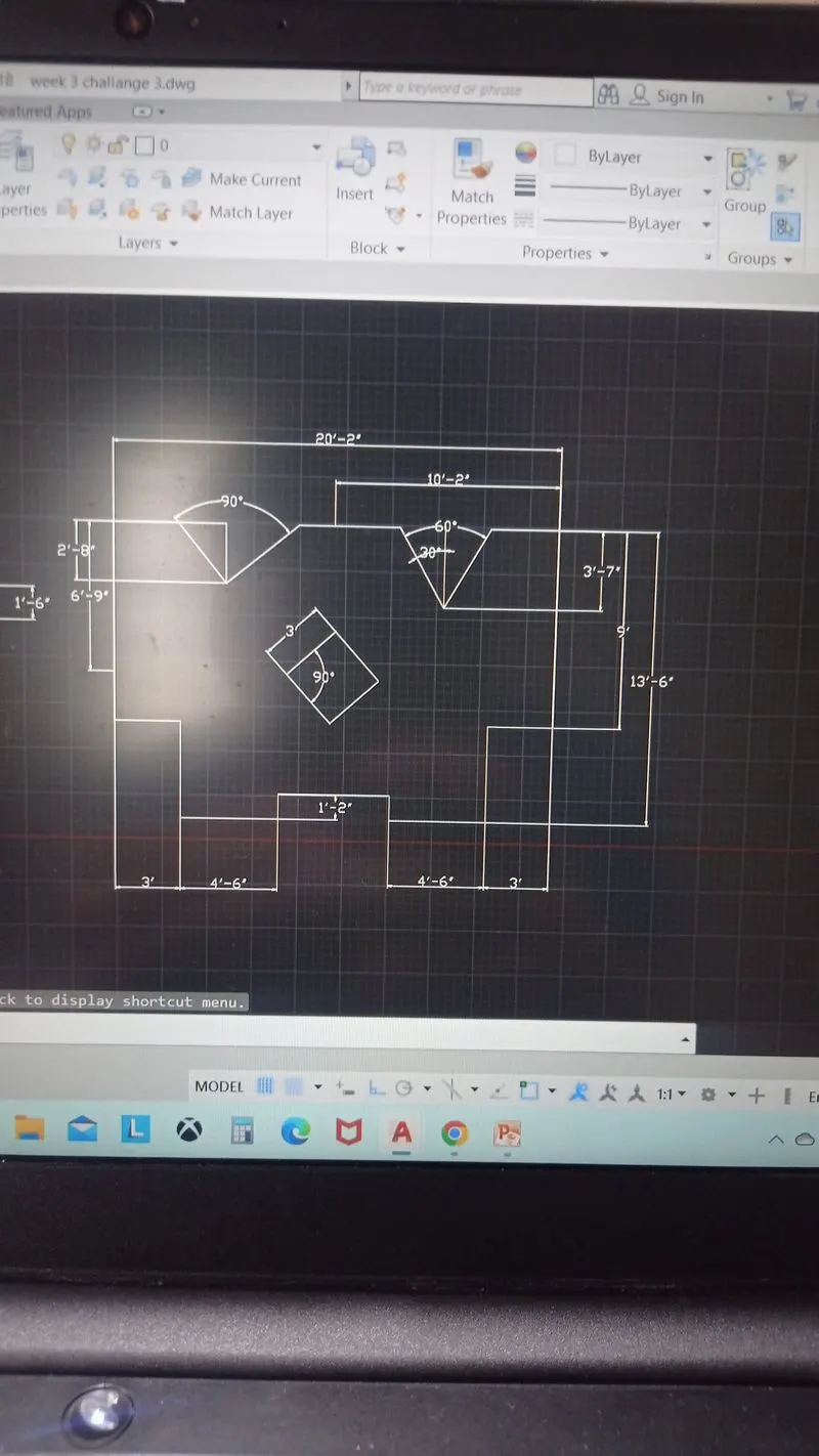
1.New sheet- units- Engineering-precision 0'-0"- feet-ok.
2. Select Line tool and draw the lengths starting from top line segment of 9'-0", changing the position of cursor in direction of the line with ortho On draw 3'-0", 4'-6",4'-6",1'-2". Now. take copy and mirror the left to right and join to close. Draw a square of side 3'-0" and rotate to 45 degrees and position it using move tool. Using ling line tool draw vertical lines of 2'-8" and 3'-7" and make 30 degrees line on each side with respect to reference vertical line and 60 degrees on the othe end.
3.Annotate and give dimension to all the line segments.