Drafting of various geometries using Chamfer, Fillet tool in AutoCad
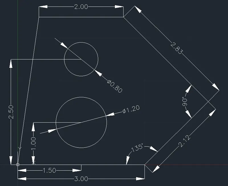
Aim & Introduction :
Drafting of various geometries using Chamfer, Fillet tool in AutoCad.
Drawing 1 :
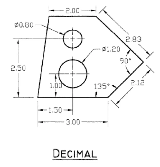
Procedure :
Enter Line command : L
Line Specify the first point : 0,0
Press F8
Line Specify the next point or [Undo] : 3 (Move mouse in Right Direction)
Line Specify the next point or [Undo] : (@2.12<45)
Line Specify the next point or [Undo] : (@2.83<135)
Line Specify the next point or [Undo] : 2 (Move mouse in Left Direction)
Line Specify the next point or [Undo] : (0,0)
Press Esc.
Now Figure :
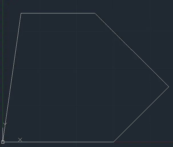
Enter Circle command : c
Specify center point for circle or [3P/2P/Ttr (tan tan radius)]: 1.50,1
Specify radius of circle or [Diameter]: d
Specify diameter of circle: 1.20
Now Figure :
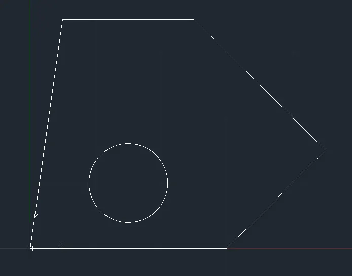
Enter Circle command : c
Specify center point for circle or [3P/2P/Ttr (tan tan radius)]: 1.50,2.50
Specify radius of circle or [Diameter] <0.60>: d
Specify diameter of circle <1.20>: 0.80
Now Figure :
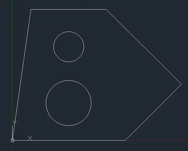
Final Figure:
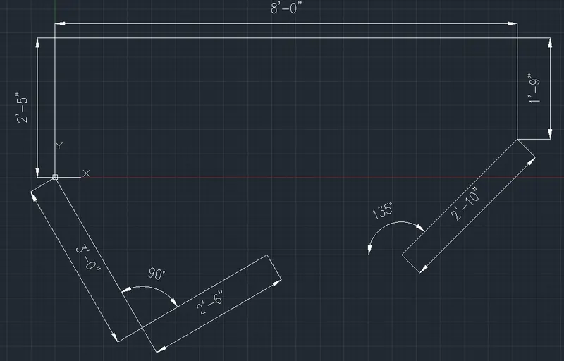
Drawing 2 :
Procedure :
Enter unit command : un
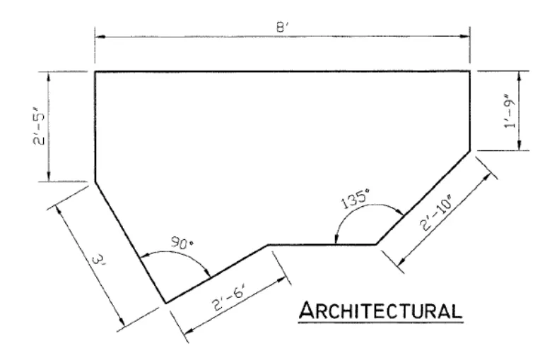
Set unit type to Architectural
Close the unit settings.
Enter Line command : L
Line Specify the first point : 0,0
Line Specify the next point or [Undo] : 2'5" (Move mouse in Upward Direction)
Line Specify the next point or [Undo] : 8' (Move mouse in Right Direction)
Line Specify the next point or [Undo] : 1'9" (Move mouse in Downward Direction)
Line Specify the next point or [Undo] : (@2'10"<225)
Line Specify the next point or [Undo] : 1' (Move mouse in Left Direction)
Press esc.
Now Figure:
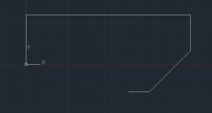
Enter Line command : L
Line Specify the first point : 0,0
Line Specify the next point or [Undo] : 3' (Move mouse in Downward Direction)
Line Specify the next point or [Undo] : 2'6" (Move mouse in Right Direction)
Press Esc.
Now Figure:
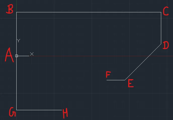
Select Lines AG and GH
Enter Rotate Command : ro
Specify base point: Point A
Specify rotation angle or [Copy/Reference] <30.18>: r
Specify the reference angle <309.81>: Point A , Specify second point: Point H
Specify the new angle or [Points] <339.98>: Track the Polar End Point F and click the line where it intersect.
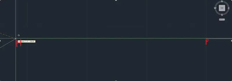
Now Figure:
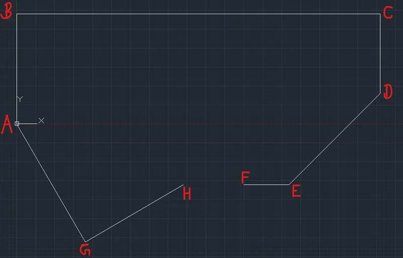
Enter Extend Command :ex
Select object to extend or shift-select to trim or [Boundary edges/Crossing/mOde/Project]: Select line EF.
Press esc.
Now, Figure:
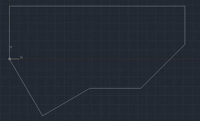
Final Figure :
Drawing 3 :
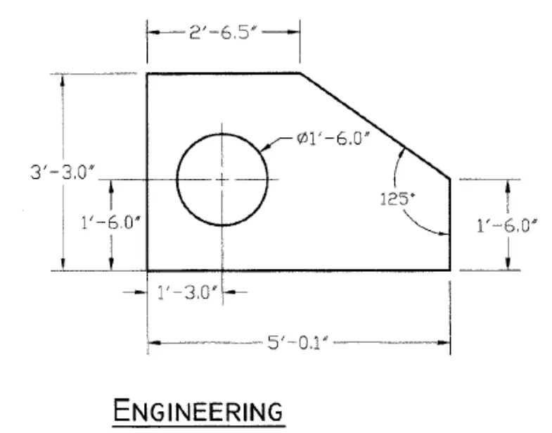
Procedure :
Enter unit command : un
Set unit type to Engineering
Close the unit settings.
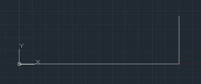
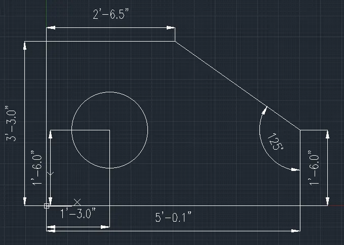
Enter Line command : L
Line Specify the first point : 0,0
Line Specify the next point or [Undo] : 5'0.1" (Move mouse in Right Direction)
Line Specify the next point or [Undo] : 1'6.0" (Move mouse in Upward Direction Direction)
press esc.
Now, Figure:
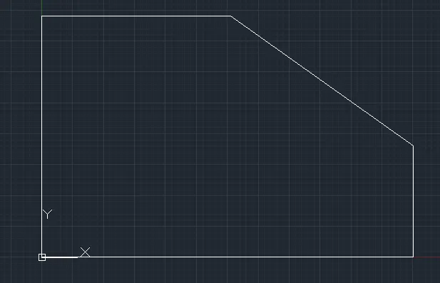
Enter Line command : L
Line Specify the first point : 0,0
Line Specify the next point or [Undo] : 3'3.0" (Move mouse in Upward Direction Direction)
Line Specify the next point or [Undo] : 2'6.5" (Move mouse in Right Direction)
Line Specify the next point or [Undo] : 5'0.1",1'6.0"
press esc.
Now, Figure:
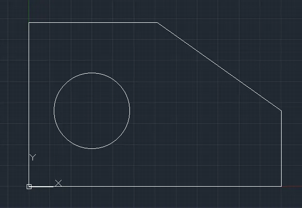
Enter Circle command : c
Specify center point for circle or [3P/2P/Ttr (tan tan radius)]: 1'3.0",1'6.0"
Specify radius of circle or [Diameter] <0.60>: d
Specify diameter of circle <1.20>: 1'6.0"
Now, Figure:
Final Figure:
Drawing 4 :
Procedure :
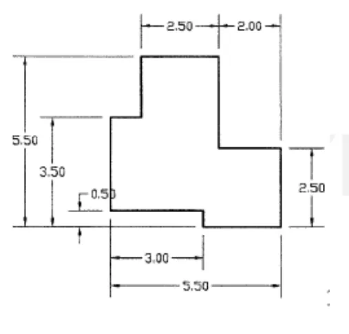
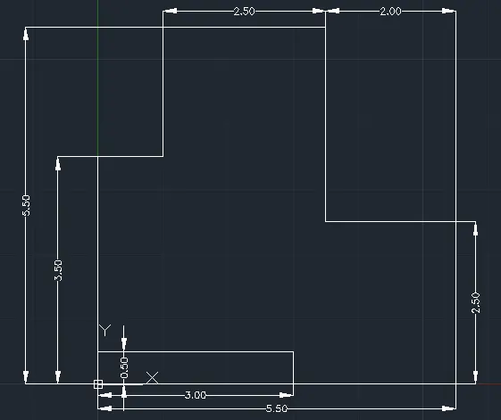
Enter Line command : L
Line Specify the first point : 0,0.50
Press F8
Line Specify the next point or [Undo] : 3 (Move mouse in Upward Direction)
Line Specify the next point or [Undo] : 1 (Move mouse in Right Direction)
Line Specify the next point or [Undo] : 2 (Move mouse in Upward Direction)
Line Specify the next point or [Undo] : 2.50 (Move mouse in Right Direction)
Line Specify the next point or [Undo] : 3 (Move mouse in Downward Direction)
Line Specify the next point or [Undo] : 2 (Move mouse in Right Direction)
Line Specify the next point or [Undo] : 2.50 (Move mouse in Downward Direction)
Line Specify the next point or [Undo] : 2.50 (Move mouse in Left Direction)
Line Specify the next point or [Undo] : 0.5 (Move mouse in Upward Direction)
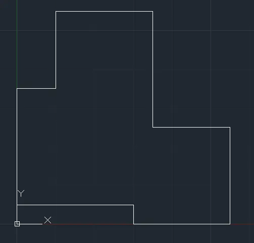
Line Specify the next point or [Undo] : 0,0.50
Now, Figure:
Final Figure:
Drawing 5 :
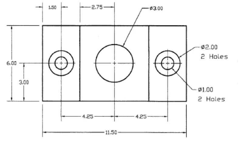
Procedure :
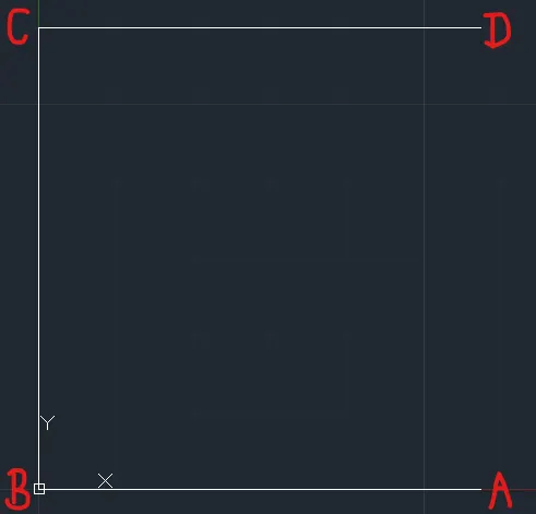
Enter Line command : L
Line Specify the first point : 5.75,0
Press F8
Line Specify the next point or [Undo] : 5.75 (Move mouse in Left Direction)
Line Specify the next point or [Undo] : 6 (Move mouse in Upward Direction)
Line Specify the next point or [Undo] : 5.75 (Move mouse in Right Direction)
press esc.
Noe, Figure:
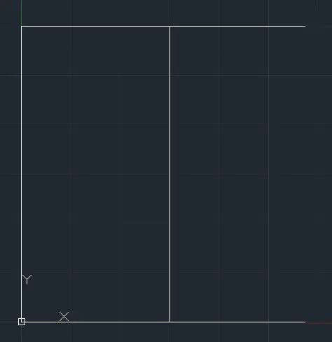
Enter offset command : o
Specify offset distance or [Through/Erase/Layer] : 3
Select object to offset or [Exit/Undo] : Select BC line
Specify point on side to offset or [Exit/Multiple/Undo] : press esc.
Now, Figure:
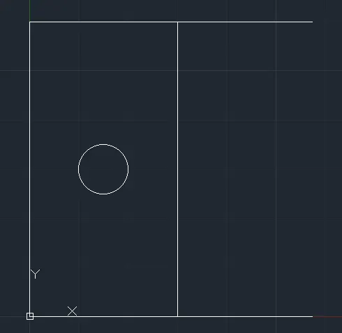
Enter Circle command : c
Specify center point for circle or [3P/2P/Ttr (tan tan radius)]: 1.50,3
Specify radius of circle or [Diameter] <0.60>: d
Specify diameter of circle <1.20>: 1
Now Figure:
Enter Circle command : c
Specify center point for circle or [3P/2P/Ttr (tan tan radius)]: 1.50,3
Specify radius of circle or [Diameter] <0.60>: d
Specify diameter of circle <1.20>: 2
Now, Figure:
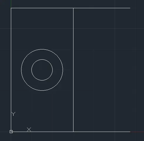
Select whole figure and
Enter Mirror Command : mi
Specify first point of mirror line: 5.75,0
Specify second point of mirror line: 5.75,6
Erase source objects? [Yes/No] : n
Now, Figure:

Enter Circle command : c
Specify center point for circle or [3P/2P/Ttr (tan tan radius)]: 5.75,3
Specify radius of circle or [Diameter] <0.60>: d
Specify diameter of circle <1.20>: 3
Now, Figure:
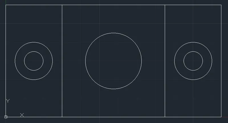
Final Figure:
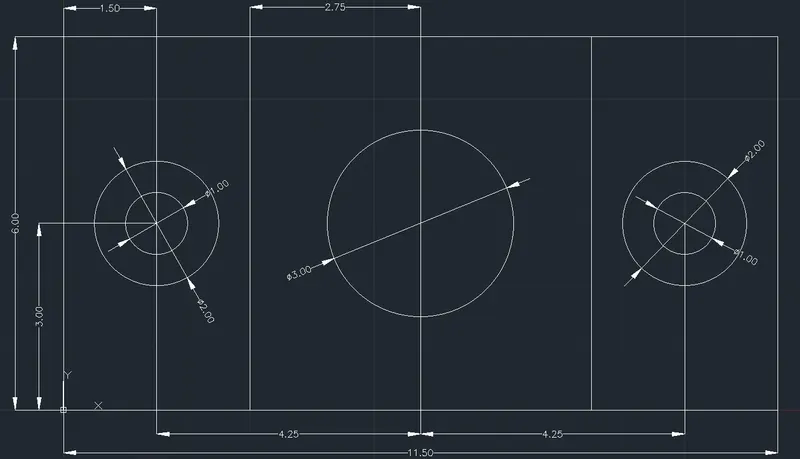
Drawing 6 :
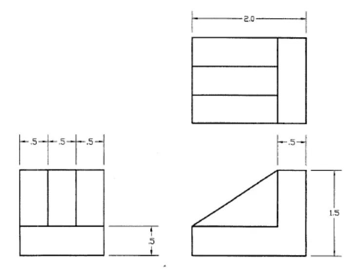
Procedure :
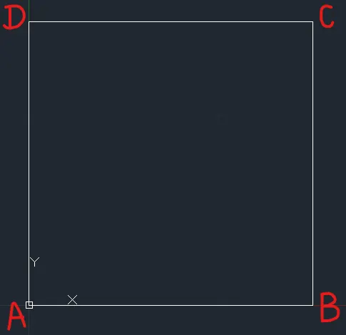
Enter Line command : L
Line Specify the first point : 0,0
Press F8
Line Specify the next point or [Undo] : 1.5 (Move mouse in Right Direction)
Line Specify the next point or [Undo] : 1.5 (Move mouse in Upward Direction)
Line Specify the next point or [Undo] : 1.5 (Move mouse in Left Direction)
Line Specify the next point or [Undo] : 1.5 (Move mouse in Downward Direction)
Press Esc.
Now, Figure:
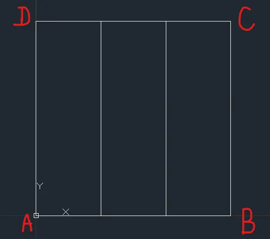
Enter offset command : o
Specify offset distance or [Through/Erase/Layer] <0.50>: 0.5
Select object to offset or [Exit/Undo] : (Select AD Line)
Specify point on side to offset or [Exit/Multiple/Undo] : m (For Multiple operations)
Specify point on side to offset or [Exit/Undo] : Move mouse in Right Direction and left click
Specify point on side to offset or [Exit/Undo] : Move mouse in Right Direction and left click
Specify point on side to offset or [Exit/Undo] : *Cancel* (Press esc.)
Now, Figure:
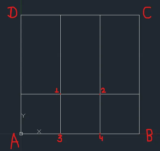
Enter offset command : o
Specify offset distance or [Through/Erase/Layer] <0.50>: 0.5
Select object to offset or [Exit/Undo] : (Select AB Line)
Specify point on side to offset or [Exit/Multiple/Undo] : Move Mouse in Upward direction and left click.
Press esc.
Now, Figure:
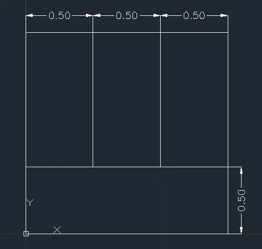
Enter trim command : tr
Select object to trim or shift-select to extend or [cuTting edges/Crossing/mOde/Project/eRase]: (Select Line 1-3)
Select object to trim or shift-select to extend or [cuTting edges/Crossing/mOde/Project/eRase/Undo]: (Select Line 2-4)
Select object to trim or shift-select to extend or [cuTting edges/Crossing/mOde/Project/eRase/Undo]: *Cancel* (Press Esc.)
Now, Figure:
Enter Line command : L
Line Specify the first point : 3,0.5
Line Specify the next point or [Undo] : 0.5 (Move mouse in Downward Direction)
Line Specify the next point or [Undo] : 2 (Move mouse in Right Direction)
Line Specify the next point or [Undo] : 1.5 (Move mouse in Upward Direction)
Line Specify the next point or [Undo] : 0.5 (Move mouse in Left Direction)
Line Specify the next point or [Undo] : (3,0.5)
Press Esc.
Now, Figure:
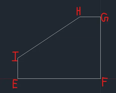
Enter offset command : o
Specify offset distance or [Through/Erase/Layer] <0.50>: 0.5
Select object to offset or [Exit/Undo] : (Select EF Line)
Specify point on side to offset or [Exit/Multiple/Undo] : Move Mouse in Upward direction and left click.
Select object to offset or [Exit/Undo] : (Select GF Line)
Specify point on side to offset or [Exit/Multiple/Undo] : Move Mouse in Left direction and left click.
Press esc.
Now, Figure:
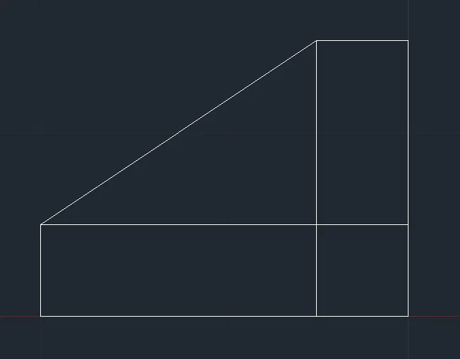
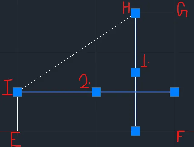
Enter Fillet command : f
Select first object or [Undo/Polyline/Radius/Trim/Multiple]: (Select Line 1)
Select second object or shift-select to apply corner or [Radius]: (Select Line 2)
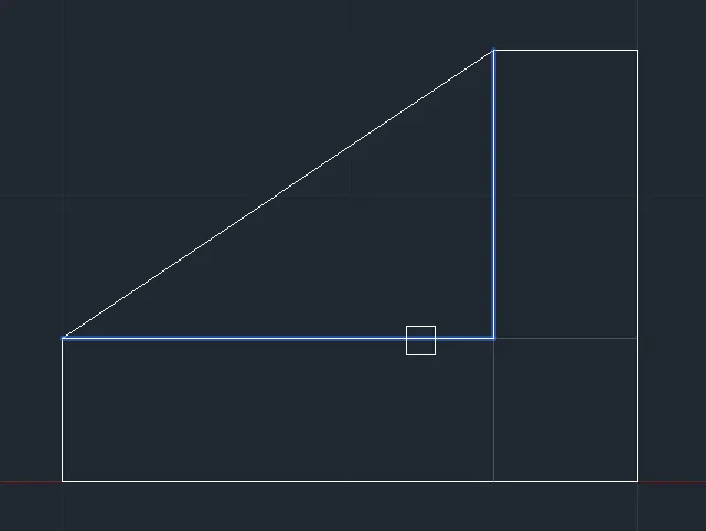
Now, Figure :
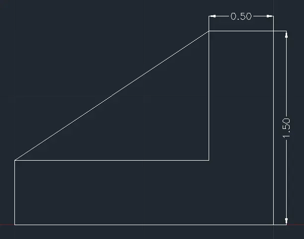
Enter Line command : L
Line Specify the first point : 3,3
Line Specify the next point or [Undo] : 2 (Move mouse in Right Direction)
Line Specify the next point or [Undo] : 1.5 (Move mouse in Upward Direction)
Line Specify the next point or [Undo] : 2 (Move mouse in Left Direction)
Line Specify the next point or [Undo] : 1.5 (Move mouse in Downward Direction)
Press Esc.
Now, Figure:
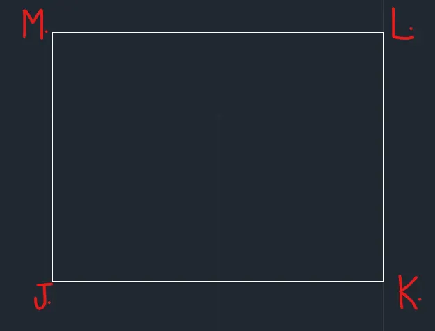
Enter offset command : o
Specify offset distance or [Through/Erase/Layer] <0.50>: 0.5
Select object to offset or [Exit/Undo] : (Select JK Line)
Specify point on side to offset or [Exit/Multiple/Undo] : m (For Multiple operations)
Specify point on side to offset or [Exit/Undo] : Move mouse in Upward Direction and left click
Specify point on side to offset or [Exit/Undo] : Move mouse in Upward Direction and left click
Specify point on side to offset or [Exit/Undo] : *Cancel* (Press esc.)
Now, Figure:
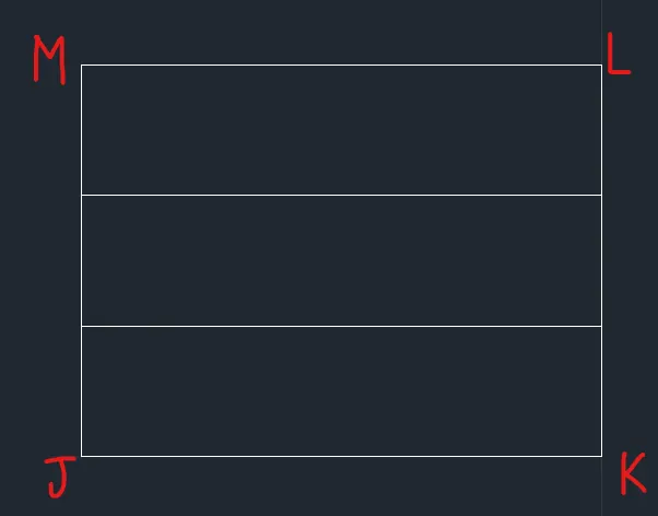
Enter offset command : o
Specify offset distance or [Through/Erase/Layer] <0.50>: 0.5
Select object to offset or [Exit/Undo] : (Select KL Line)
Specify point on side to offset or [Exit/Multiple/Undo] : Move Mouse in Left direction and left click.
Press esc.
Now, Figure:
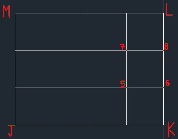
Enter trim command : tr
Select object to trim or shift-select to extend or [cuTting edges/Crossing/mOde/Project/eRase]: (Select Line 5-6)
Select object to trim or shift-select to extend or [cuTting edges/Crossing/mOde/Project/eRase/Undo]: (Select Line 7-8)
Select object to trim or shift-select to extend or [cuTting edges/Crossing/mOde/Project/eRase/Undo]: *Cancel* (Press Esc.)
Now, Figure:
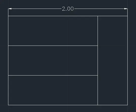
Final Figure:
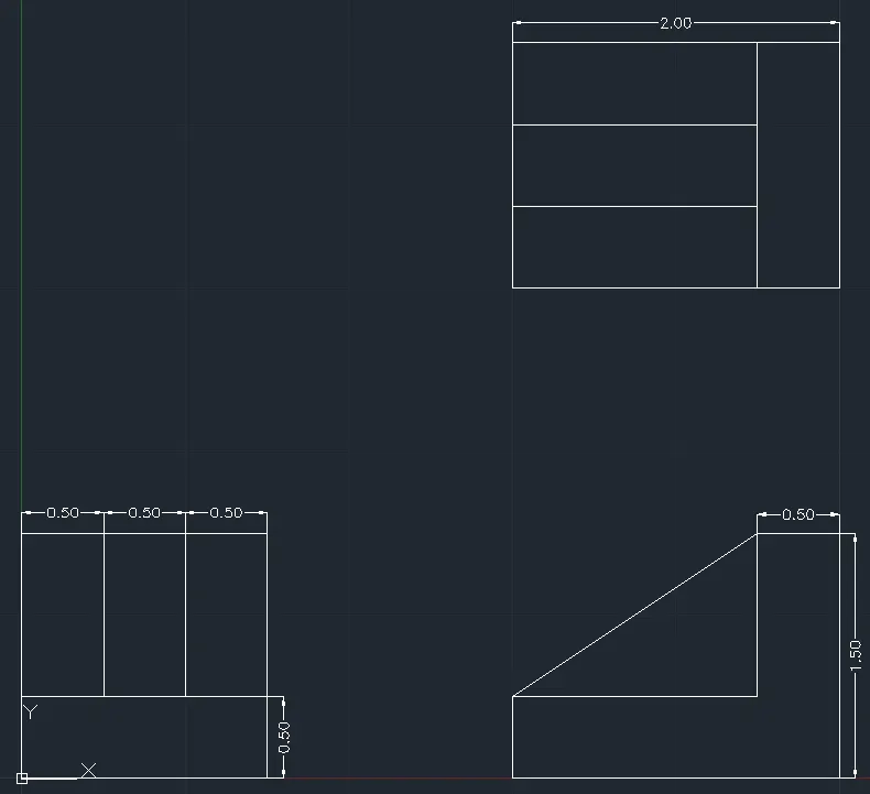
Drawing 7 :
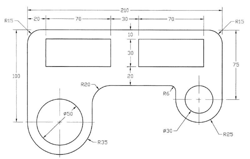
Procedure :
Enter Line command : L
Line Specify the first point : 0,0
Press F8
Line Specify the next point or [Undo] : 100 (Move mouse in Upward Direction)
Line Specify the next point or [Undo] : 210 (Move mouse in Right Direction)
Line Specify the next point or [Undo] : 75 (Move mouse in Downward Direction)
Press Esc.
Now, Figure:
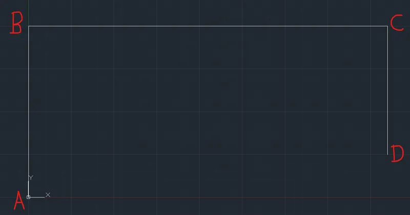
Enter offset Command : o
Specify offset distance or [Through/Erase/Layer] <0.50>: 70
Select object to offset or [Exit/Undo] : (Select AB)
Specify point on side to offset or [Exit/Multiple/Undo] : (Move Mouse in Right Direction and left click)
Select object to offset or [Exit/Undo] : *Cancel* (Press Esc.)
Enter offset Command : o
Specify offset distance or [Through/Erase/Layer] <0.50>: 60
Select object to offset or [Exit/Undo] : (Select BC)
Specify point on side to offset or [Exit/Multiple/Undo] : (Move Mouse in Downward Direction and left click)
Select object to offset or [Exit/Undo] : *Cancel* (Press Esc.)
Enter offset Command : o
Specify offset distance or [Through/Erase/Layer] <0.50>: 50
Select object to offset or [Exit/Undo] : (Select CD)
Specify point on side to offset or [Exit/Multiple/Undo] : (Move Mouse in Left Direction and left click)
Select object to offset or [Exit/Undo] : *Cancel* (Press Esc.)
Now, Figure:
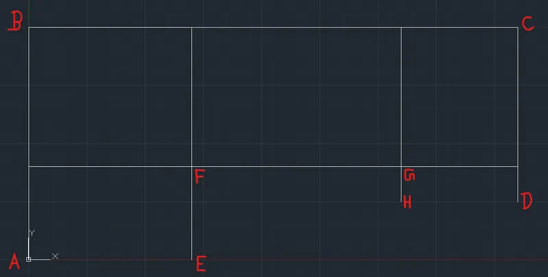
Enter Fillet command : f
Select first object or [Undo/Polyline/Radius/Trim/Multiple]: (Select EF)
Select second object or shift-select to apply corner or [Radius]: (Select FG)
Enter Fillet command : f
Select first object or [Undo/Polyline/Radius/Trim/Multiple]: (Select FG)
Select second object or shift-select to apply corner or [Radius]: (Select GH)
Now, Figure:
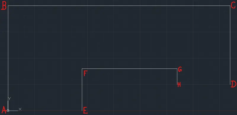
Enter offset Command : o
Specify offset distance or [Through/Erase/Layer] <0.50>: 20
Select object to offset or [Exit/Undo] : (Select AB)
Specify point on side to offset or [Exit/Multiple/Undo] : (Move Mouse in Right Direction and left click)
Select object to offset or [Exit/Undo] : *Cancel* (Press Esc.)
Enter offset Command : o
Specify offset distance or [Through/Erase/Layer] <0.50>: 10
Select object to offset or [Exit/Undo] : (Select BC)
Specify point on side to offset or [Exit/Multiple/Undo] : (Move Mouse in Downward Direction and left click)
Select object to offset or [Exit/Undo] : *Cancel* (Press Esc.)
Enter offset Command : o
Specify offset distance or [Through/Erase/Layer] <0.50>: 90
Select object to offset or [Exit/Undo] : (Select AB)
Specify point on side to offset or [Exit/Multiple/Undo] : (Move Mouse in Right Direction and left click)
Select object to offset or [Exit/Undo] : *Cancel* (Press Esc.)
Enter offset Command : o
Specify offset distance or [Through/Erase/Layer] <0.50>: 40
Select object to offset or [Exit/Undo] : (Select BC)
Specify point on side to offset or [Exit/Multiple/Undo] : (Move Mouse in Downward Direction and left click)
Select object to offset or [Exit/Undo] : *Cancel* (Press Esc.)
Now, Figure:
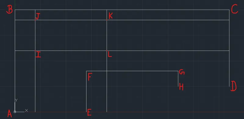
Enter Fillet command : f
Select first object or [Undo/Polyline/Radius/Trim/Multiple]: (Select IJ)
Select second object or shift-select to apply corner or [Radius]: (Select JK)
Enter Fillet command : f
Select first object or [Undo/Polyline/Radius/Trim/Multiple]: (Select JK)
Select second object or shift-select to apply corner or [Radius]: (Select KL)
Enter Fillet command : f
Select first object or [Undo/Polyline/Radius/Trim/Multiple]: (Select KL)
Select second object or shift-select to apply corner or [Radius]: (Select LI)
Enter Fillet command : f
Select first object or [Undo/Polyline/Radius/Trim/Multiple]: (Select LI)
Select second object or shift-select to apply corner or [Radius]: (Select IJ)
Now, Figure:
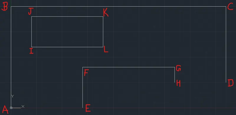
Select Lines - IJ, JK, KL, LI
Enter Mirror Command : mi
Specify first point of mirror line: (Take Mid Point of Line BC)
Specify second point of mirror line: (Move Mouse in upward Direction and left click)
Erase source objects? [Yes/No] : n
Now, Figure:
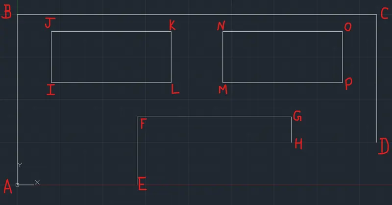
Enter Fillet Command : f
Select first object or [Undo/Polyline/Radius/Trim/Multiple]: r
Specify fillet radius <0.00>: 15
Select first object or [Undo/Polyline/Radius/Trim/Multiple]: (Select AB)
Select second object or shift-select to apply corner or [Radius]: (Select BC)
Enter Fillet Command : f
Select first object or [Undo/Polyline/Radius/Trim/Multiple]: r
Specify fillet radius <0.00>: 15
Select first object or [Undo/Polyline/Radius/Trim/Multiple]: (Select BC)
Select second object or shift-select to apply corner or [Radius]: (Select CD)
Enter Fillet Command : f
Select first object or [Undo/Polyline/Radius/Trim/Multiple]: r
Specify fillet radius <0.00>: 20
Select first object or [Undo/Polyline/Radius/Trim/Multiple]: (Select EF)
Select second object or shift-select to apply corner or [Radius]: (Select FG)
Enter Fillet Command : f
Select first object or [Undo/Polyline/Radius/Trim/Multiple]: r
Specify fillet radius <0.00>: 6
Select first object or [Undo/Polyline/Radius/Trim/Multiple]: (Select FG)
Select second object or shift-select to apply corner or [Radius]: (Select GH)
Now, Figure:
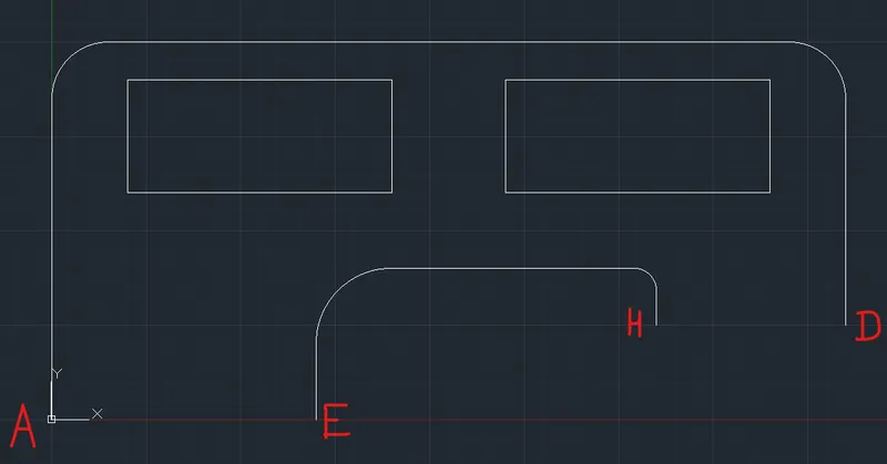
Go to Home and Arc dropdown List select Arc,Start,End,Radius
Specify Start point of arc: (Point A)
Specify Start point of arc: (Point E)
Specify radius of arc (hold Ctrl to switch direction): 35
Now, Figure:
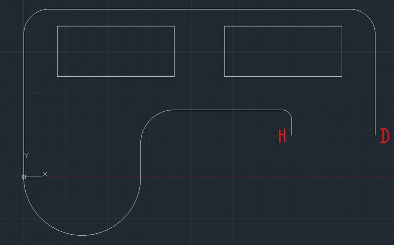
Go to Home and Arc dropdown List select Arc,Start,End,Radius
Specify Start point of arc: (Point A)
Specify Start point of arc: (Point E)
Specify radius of arc (hold Ctrl to switch direction): 25
Now, Figure:
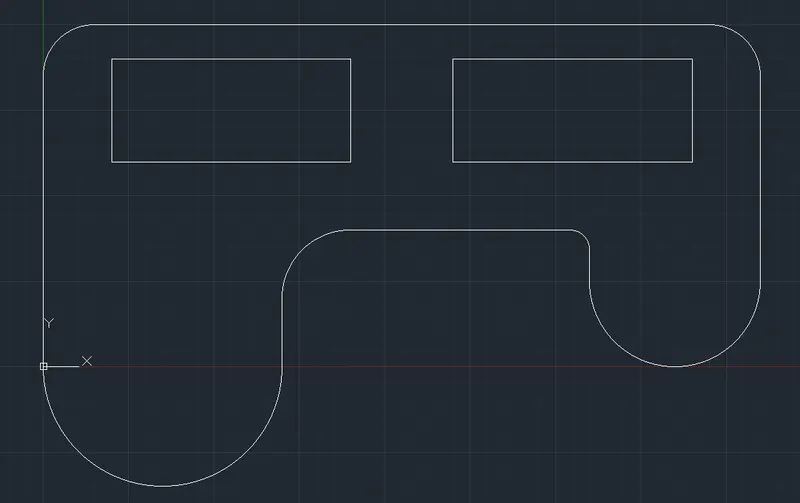
Enter Circle command : c
Specify center point for circle or [3P/2P/Ttr (tan tan radius)]: 35,0
Specify radius of circle or [Diameter]: d
Specify diameter of circle: 50
Now Figure :
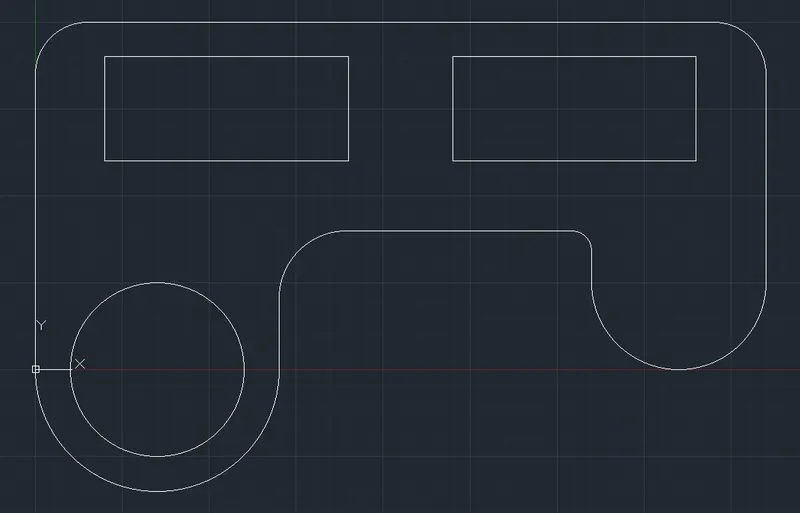
Enter Circle command : c
Specify center point for circle or [3P/2P/Ttr (tan tan radius)]: 185,25
Specify radius of circle or [Diameter]: d
Specify diameter of circle: 30
Now Figure :
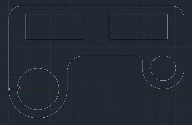
Final Figure:
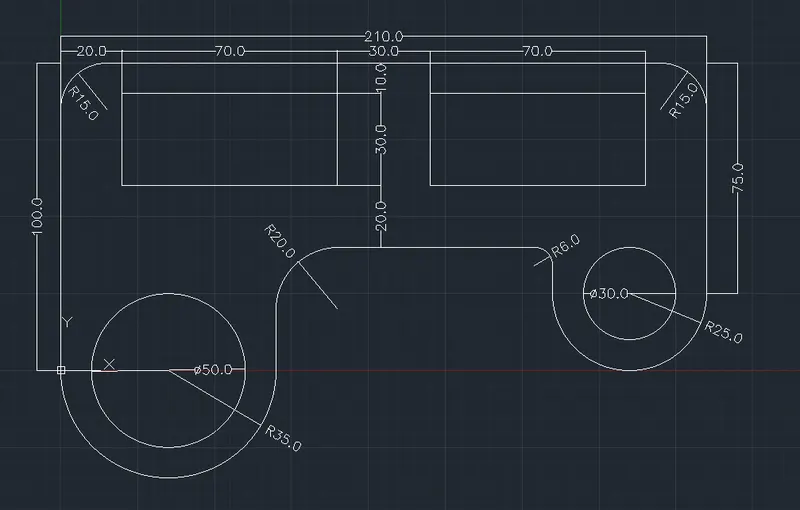
Drawing 8 :
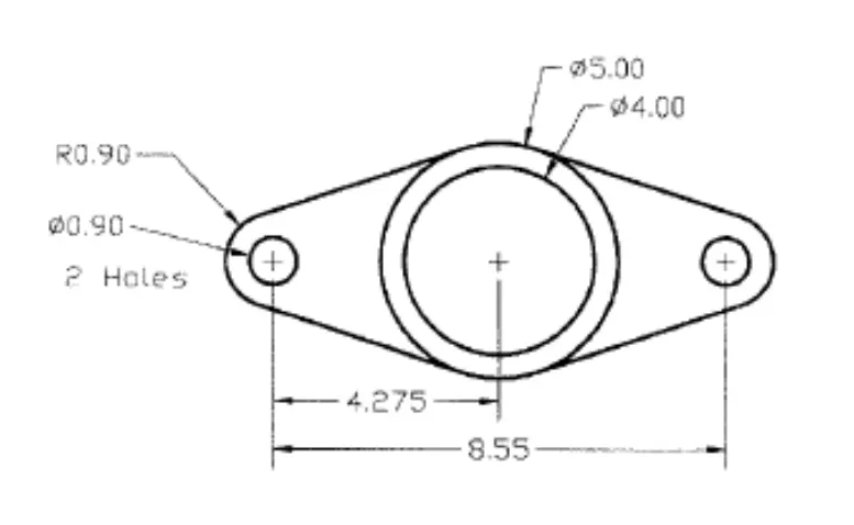
Procedure :
Enter Circle command : c
Specify center point for circle or [3P/2P/Ttr (tan tan radius)]: 185,25
Specify radius of circle or [Diameter]: d
Specify diameter of circle: 4
Now, Figure:
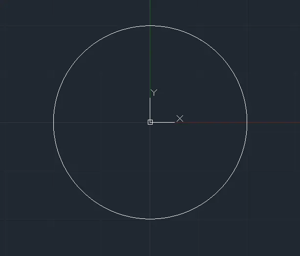
Enter offset command : o
Specify offset distance or [Through/Erase/Layer] : 0.5
Select object to offset or [Exit/Undo] : Select Circle (Move Mouse outward the circle)
Specify point on side to offset or [Exit/Multiple/Undo] : press esc.
Now, Figure:
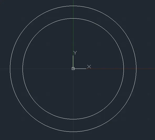
Enter Circle command : c
Specify center point for circle or [3P/2P/Ttr (tan tan radius)]: 4.275,0
Specify radius of circle or [Diameter]: d
Specify diameter of circle: 0.9
Now, Figure:
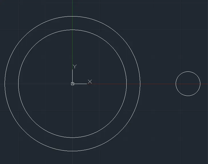
Enter Line Command : l
Line Specify the first point : 6.6,0
Press F8 (Ortho off)
Line Specify the next point or [Undo] : (Move mouse in Near to the bigger circle Left-Upward Direction)
Track the Tangent Point on the circle and left click.
Press Esc.
Now, figure:
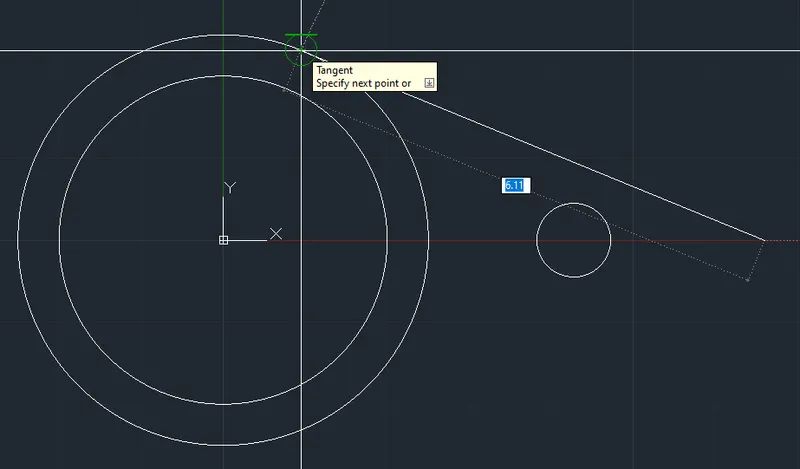
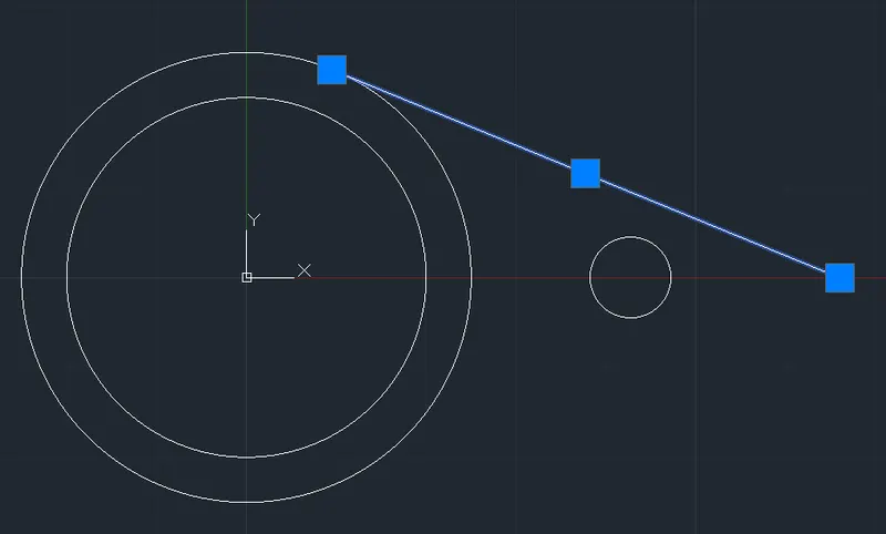
Press F8 (Ortho on)
Select the tangent line , Enter Mirror Command : mi
Specify first point of mirror line: 6.6,0
Specify second point of mirror line: 0,0
Erase source objects? [Yes/No] : n
Now, Figure:
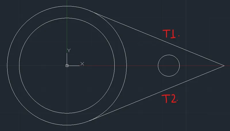
Enter Fillet command : f
Select first object or [Undo/Polyline/Radius/Trim/Multiple]: r
Specify fillet radius <0.00>: 0.9
Select first object or [Undo/Polyline/Radius/Trim/Multiple]: (Select T1)
Select second object or shift-select to apply corner or [Radius]: (Select T2)
Now, Figure:
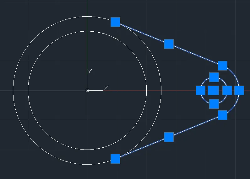
Select the Tangent, Arc & Circle together and , Enter Mirror Command : mi
Specify first point of mirror line: 0,0
Specify second point of mirror line: 0,5
Erase source objects? [Yes/No] : n
Now, Figure:
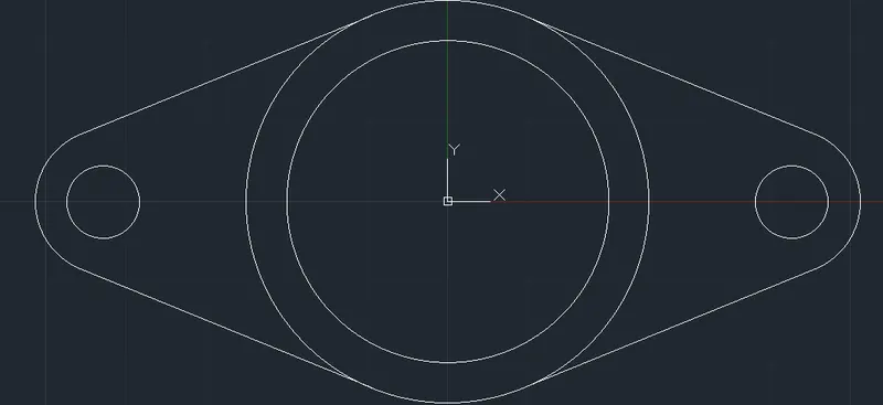
Final Figure:
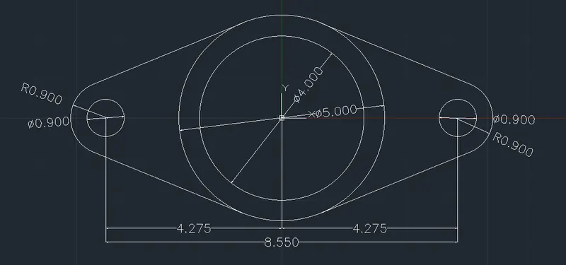
Drawing 9 :
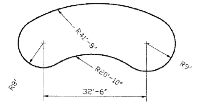
Procedure :
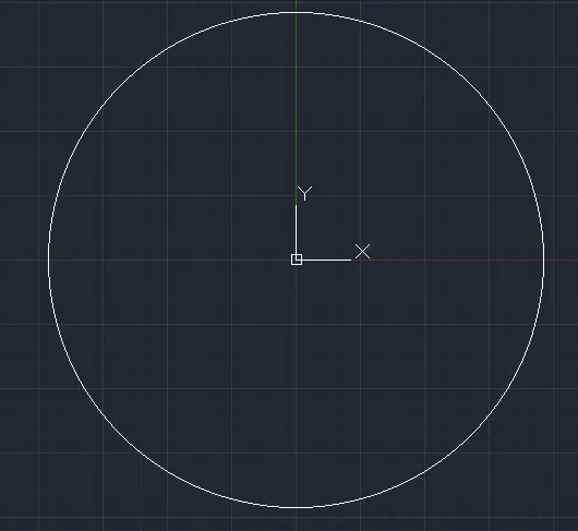
Enter Circle command : c
Specify center point for circle or [3P/2P/Ttr (tan tan radius)]: 0,0
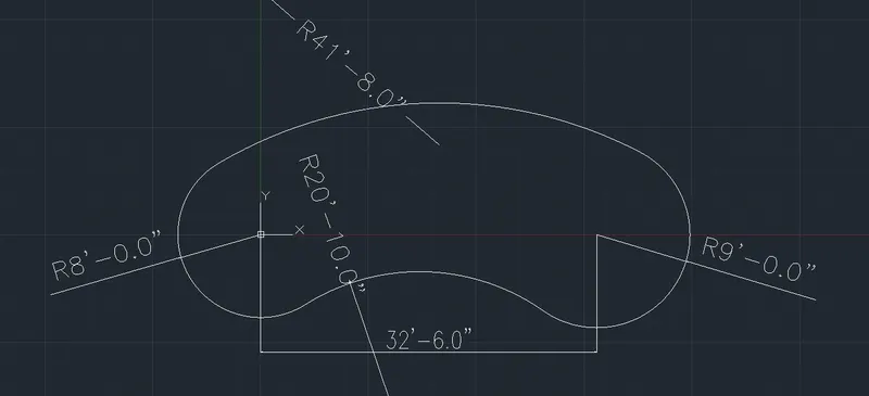
Specify radius of circle or [Diameter]: 8'
Now, Figure:
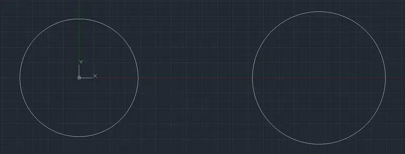
Enter Circle command : c
Specify center point for circle or [3P/2P/Ttr (tan tan radius)]: 32'6",0
Specify radius of circle or [Diameter]: 9'
Now, Figure:
Enter circle command : c
Specify center point for circle or [3P/2P/Ttr (tan tan radius)]: T (tan tan radius)
Specify point on object for first tangent of circle: (Select any tangent point on Left Circle - left side)
Specify point on object for second tangent of circle: (Select any tangent point on Right Circle - Right side)
Specify radius of circle <9'-0.00">: 41'8"
Now, Figure:
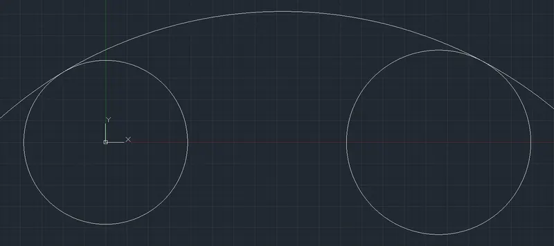
Now enter Trim command : tr
Select object to trim or shift-select to extend or [cuTting edges/Crossing/mOde/Project/eRase]: (Select Line Extra outside the left circle)
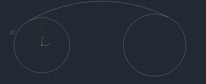
Select object to trim or shift-select to extend or [cuTting edges/Crossing/mOde/Project/eRase/Undo]: *Cancel* (Press Esc.)
Now, Figure:

Enter circle command : c
Specify center point for circle or [3P/2P/Ttr (tan tan radius)]: T (tan tan radius)
Specify point on object for first tangent of circle: (Select any tangent point on Left Circle - Right side bottom)
Specify point on object for second tangent of circle: (Select any tangent point on Right Circle - Left side bottom)
Specify radius of circle <9'-0.00">: 20'10"
Now, Figure:
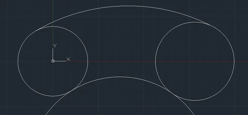
Now enter Trim command : tr
Select object to trim or shift-select to extend or [cuTting edges/Crossing/mOde/Project/eRase]: (Select Line Extra outside the left circle)
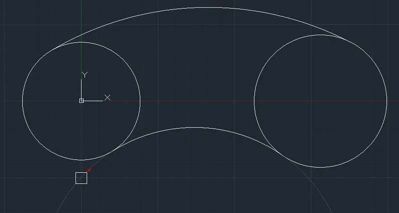
Select object to trim or shift-select to extend or [cuTting edges/Crossing/mOde/Project/eRase/Undo]: *Cancel* (Press Esc.)
Now, Figure:
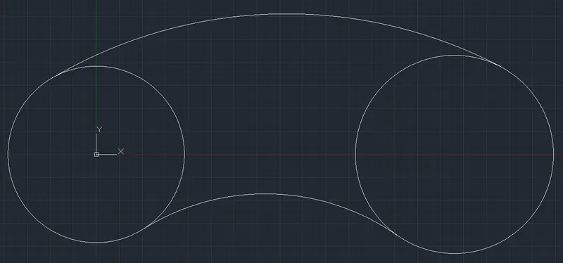
Now enter Trim command : tr
Select object to trim or shift-select to extend or [cuTting edges/Crossing/mOde/Project/eRase]: (Select both Circle Line between the Top and bottom Arc)
Select object to trim or shift-select to extend or [cuTting edges/Crossing/mOde/Project/eRase/Undo]: *Cancel* (Press Esc.)
Now, Figure:
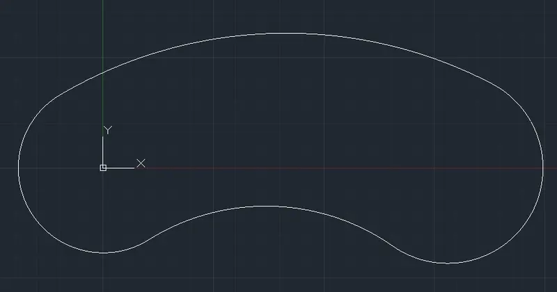
Final Figure:
Drawing 10 :
Procedure :
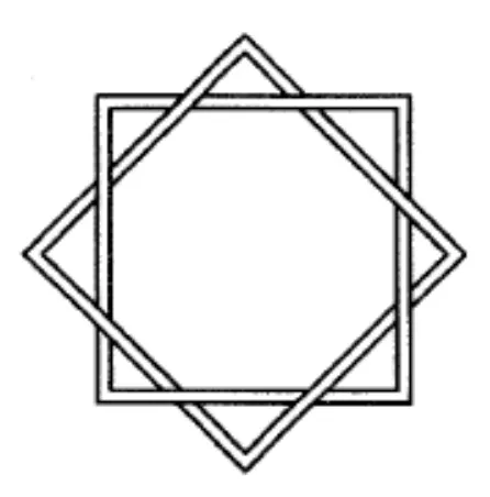
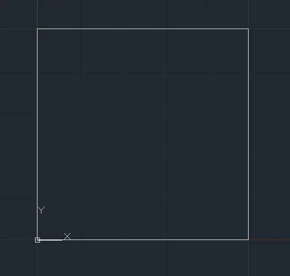
Enter Rectangle command : rec
Specify first corner point or [Chamfer/Elevation/Fillet/Thickness/Width]: 0,0
Specify other corner point or [Area/Dimensions/Rotation]: 5,5
Now, Figure:
Enter offset command : o
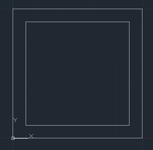
Specify offset distance or [Through/Erase/Layer] : 0.5
Select object to offset or [Exit/Undo] : Select Rectangle (Move Mouse Inside the box)
Specify point on side to offset or [Exit/Multiple/Undo] : press esc.
Now, Figure:
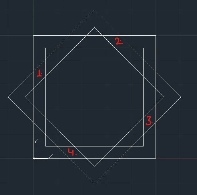
Select Both Objects and Enter Rotate Command : ro
Specify base point: (Center of the Box)
Specify rotation angle or [Copy/Reference] <0.00>: c Rotating a copy of the selected objects.
Specify rotation angle or [Copy/Reference] <0.00>: 45
Now, Figure:
Enter trim command : tr
Select object to trim or shift-select to extend or [cuTting edges/Crossing/mOde/Project/eRase]: (Select Line Near point 1)
Select object to trim or shift-select to extend or [cuTting edges/Crossing/mOde/Project/eRase/Undo]: (Select Line Near point 2)
Select object to trim or shift-select to extend or [cuTting edges/Crossing/mOde/Project/eRase/Undo]: (Select Line Near point 3)
Select object to trim or shift-select to extend or [cuTting edges/Crossing/mOde/Project/eRase/Undo]: (Select Line Near point 4)
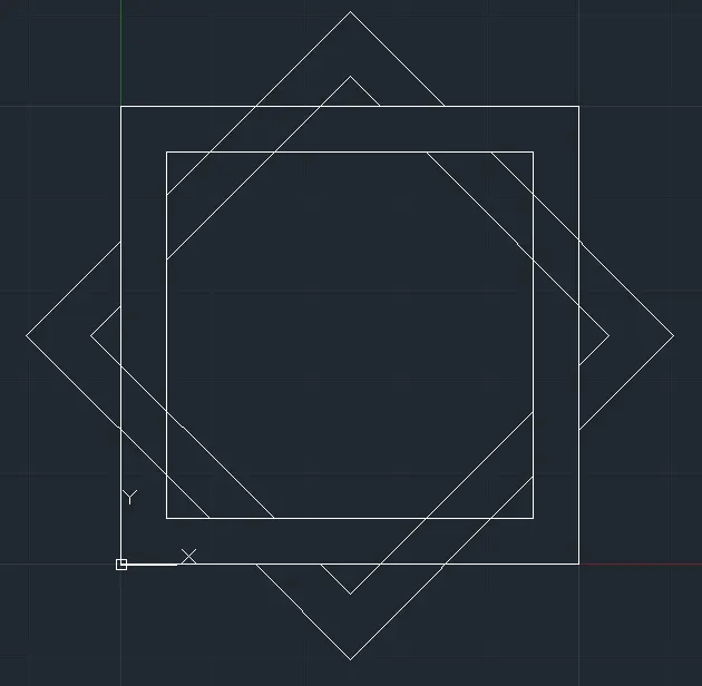
Select object to trim or shift-select to extend or [cuTting edges/Crossing/mOde/Project/eRase/Undo]: *Cancel* (Press Esc.)
Final Figure:
Drawing 11 :
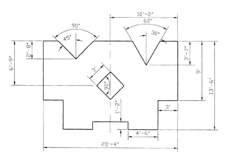
Procedure :
Enter Line command : L
Line Specify the first point : 3',0
Press F8
Line Specify the next point or [Undo] : 4'6" (Move mouse in Right Direction)
Line Specify the next point or [Undo] : 1'2" (Move mouse in Upward Direction)
Line Specify the next point or [Undo] : 5'4" (Move mouse in Right Direction)
Line Specify the next point or [Undo] : 1'2" (Move mouse in Downward Direction)
Line Specify the next point or [Undo] : 4'6" (Move mouse in Right Direction)
Line Specify the next point or [Undo] : 9' (Move mouse in Upward Direction)
Line Specify the next point or [Undo] : 2'6" (Move mouse in Left Direction)
Line Specify the next point or [Undo] : 3'7" (Move mouse in Downward Direction)
Line Specify the next point or [Undo] : 4' (Move mouse in Left Direction)
Line Specify the next point or [Undo] : 3'7" (Move mouse in Upward Direction)
Press Esc.
Now, Figure:
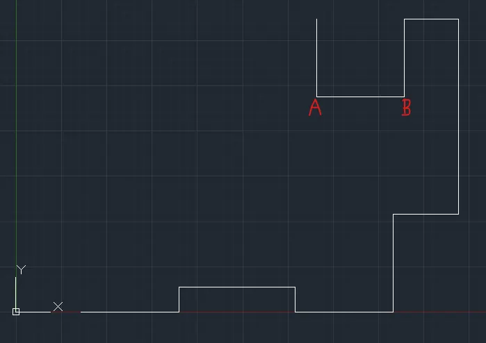
Enter Line Command : l
Line Specify the first point : Center of Line AB
Line Specify the next point or [Undo] : 3'7" (Move mouse in Upward Direction)
Press esc.
Now, Figure:
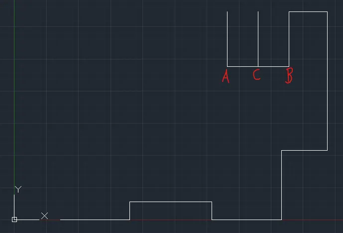
Enter Line Command : l
Line Specify the first point : Point C
Line Specify the next point or [Undo] : @2'<60
Press esc.
Now, Figure:
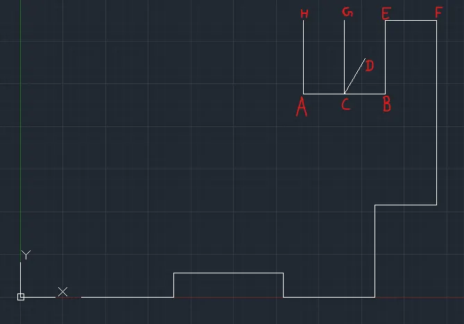
Now Extend Line CD to EF Enter extend command : ex
Select object to extend or shift-select to trim or [Boundary edges/Crossing/mOde/Project]: Select CD
Press esc.
Now, Figure:
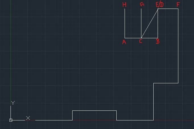
Select Line CD and Enter Mirror Command : mi
Specify first point of mirror line: Point C
Specify second point of mirror line: Point G
Erase source objects? [Yes/No] : n
Now, Figure:
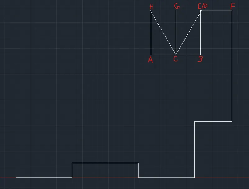
Select line AB , AH , CG , BE and enter erase command : e
Now, Figure:
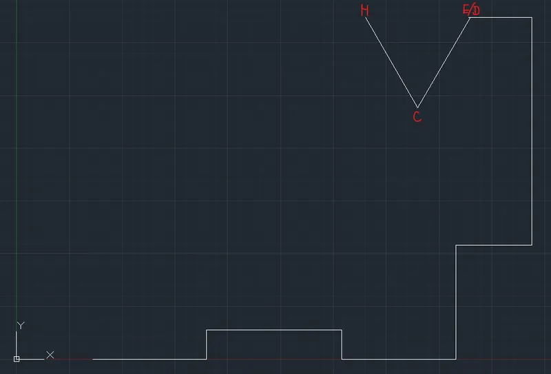
Now Select CH and CD line and move from point D to point E,
Enter Move command : m
Specify base point or [Displacement] <Displacement>: Point D
Specify second point or <use first point as displacement>: Point E
Now, Figure:
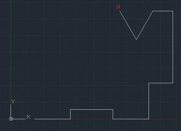
Enter Line Command : l
Line Specify the first point : Point H
Line Specify the next point or [Undo] : 6'2.35" (Move mouse in Left Direction)
Line Specify the next point or [Undo] : 2'8" (Move mouse in Downward Direction)
Line Specify the next point or [Undo] : 4' (Move mouse in Left Direction)
Line Specify the next point or [Undo] : 2'8" (Move mouse in Upward Direction)
Press esc.
Now, Figure:
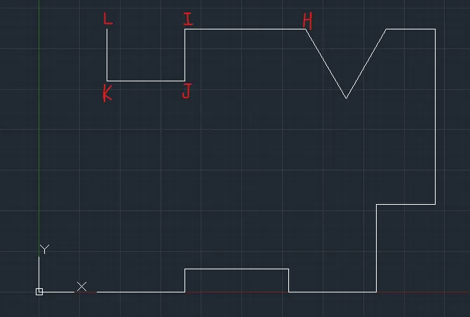
Enter Line Command : l
Line Specify the first point : Center of Line JK
Line Specify the next point or [Undo] : 2'8" (Move mouse in Upward Direction)
Press esc.
Now, Figure:
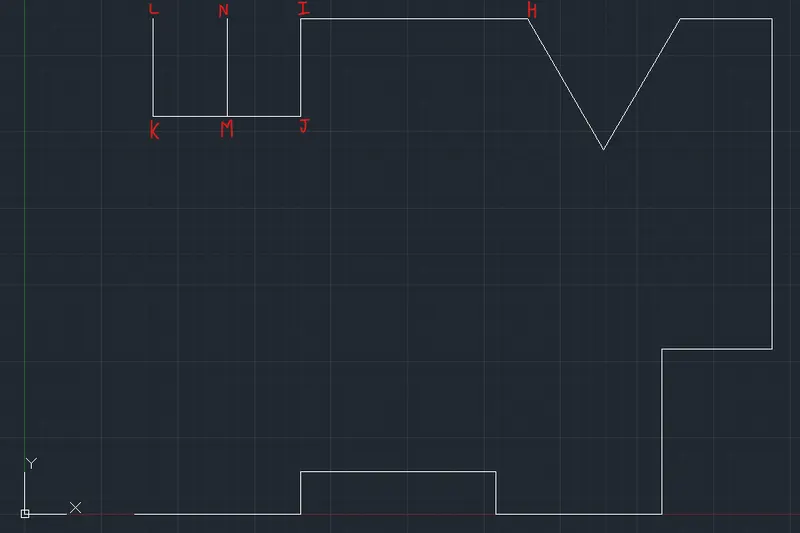
Enter Line Command : l
Line Specify the first point : Point M
Line Specify the next point or [Undo] : @2'<45
Press esc.
Now, Figure:
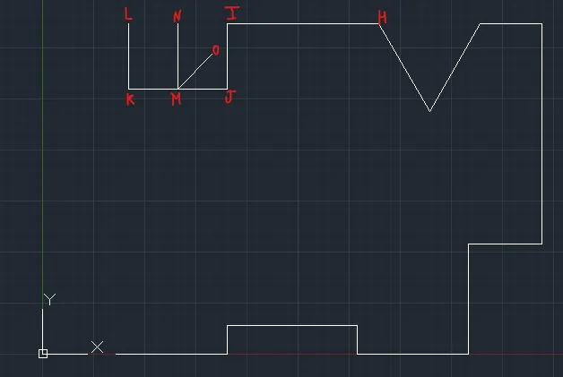
Now Extend Line CD to EF Enter extend command : ex
Select object to extend or shift-select to trim or [Boundary edges/Crossing/mOde/Project]: Select MO
Select object to extend or shift-select to trim or [Boundary edges/Crossing/mOde/Project]: Select MO
Press esc.
Now, Figure:
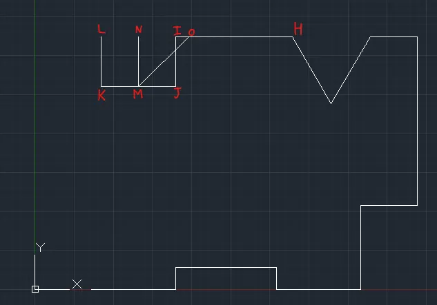
Select Line MO and Enter Mirror Command : mi
Specify first point of mirror line: Point M
Specify second point of mirror line: Point N
Erase source objects? [Yes/No] : n
Now, Figure:
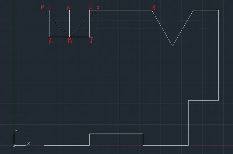
Select line KL , MN , IJ , JK and enter erase command : e
Now, Figure:
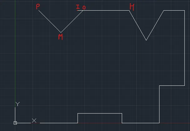
Now Select MP and MO line and move from point O to point I,
Enter Move command : m
Specify base point or [Displacement] <Displacement>: Point O
Specify second point or <use first point as displacement>: Point I
Now, Figure:
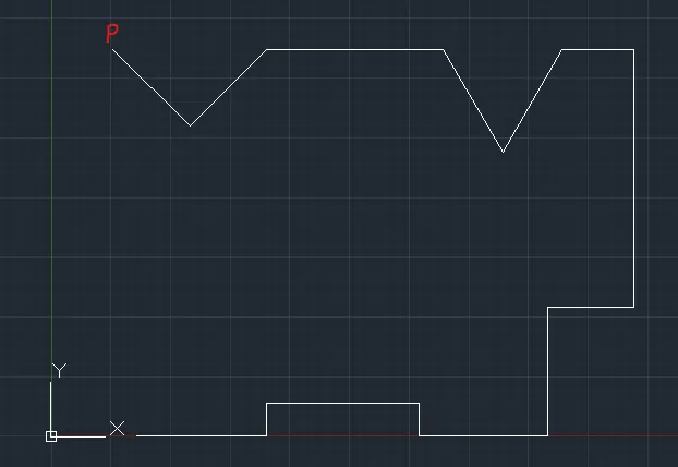
Enter Line Command : l
Line Specify the first point : Point P
Line Specify the next point or [Undo] : 0.13'6"
Line Specify the next point or [Undo] : 9' (Move mouse in Downward Direction)
Line Specify the next point or [Undo] : 3' (Move mouse in Right Direction)
Line Specify the next point or [Undo] : 3',0
Press esc.
Now, Figure:
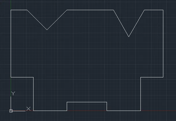
Enter Rectangle command : rec
Specify first corner point or [Chamfer/Elevation/Fillet/Thickness/Width]: 0,0
Specify other corner point or [Area/Dimensions/Rotation]: 3',3'
Now, Figure:
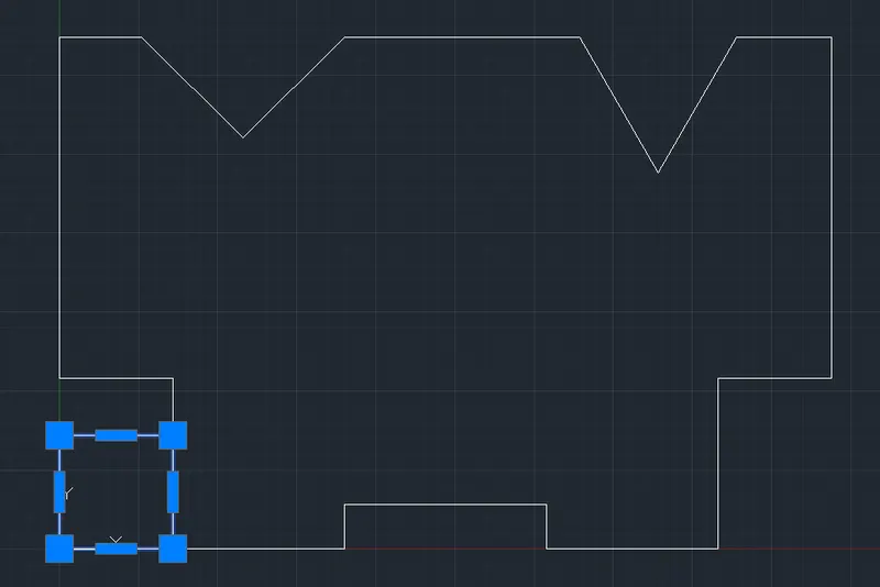
Select the rectangle drawn and enter move command : m
Specify base point or [Displacement] <Displacement>: (Center of the rectangle)
Specify second point or <use first point as displacement>: 10'2",6'9"
Now Figure:
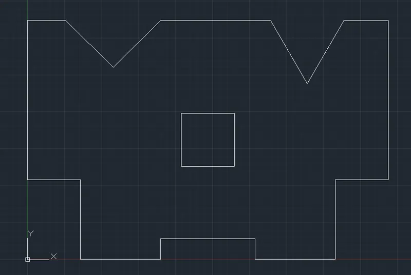
Select the middle rectangle and enter rotate command : ro
Specify base point: (Center of the Box)
Specify rotation angle or [Copy/Reference] <0.00>: 45
Now, Figure:
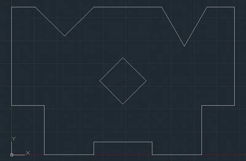
Final Figure:
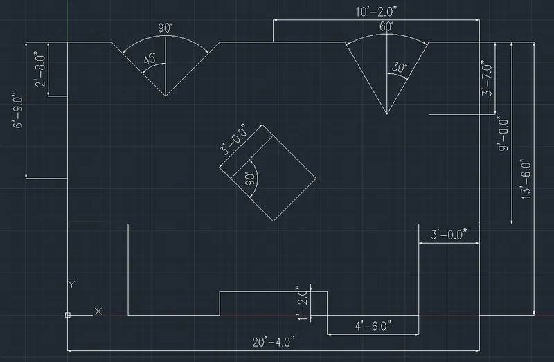
Final Result :
All the Figure are successfully drawn correctly.