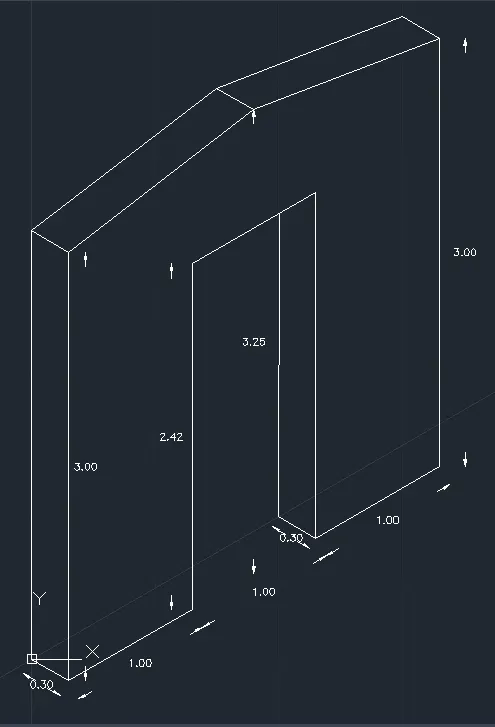
Creating a Floor plan, Footing detail and Isometric view using AutoCad
Aim & Introduction :
Creating a Floor plan, Footing detail and Isometric view of the given drawings using AutoCad.
Drawing 1 :
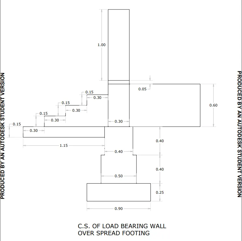
Procedure :
Enter Line command : L
Line Specify the first point : 0,0
Press F8
Line Specify the next point or [Undo] : 0.30 (Move mouse in Right Direction)
Line Specify the next point or [Undo] : 0.15 (Move mouse in Upward Direction)
Line Specify the next point or [Undo] : 0.30 (Move mouse in Right Direction)
Line Specify the next point or [Undo] : 0.15 (Move mouse in Upward Direction)
Line Specify the next point or [Undo] : 0.30 (Move mouse in Right Direction)
Line Specify the next point or [Undo] : 0.15 (Move mouse in Upward Direction)
Line Specify the next point or [Undo] : 0.30 (Move mouse in Right Direction)
Line Specify the next point or [Undo] : 0.15 (Move mouse in Upward Direction)
Line Specify the next point or [Undo] : 0.30 (Move mouse in Right Direction)
Line Specify the next point or [Undo] : 1.15 (Move mouse in Right Direction)
Line Specify the next point or [Undo] : 0.60 (Move mouse in Downward Direction)
Line Specify the next point or [Undo] : 0.30,0 & press esc.
Select The line AB = 0.30 (See Fig. below)
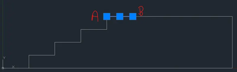
Give Offset Command : o
OFFSET Specify Offset distance : 0.05 (Move the Mouse in Upward Direction and left click & Press esc.)
Enter Line Command : L
Line Specify the first point : (Left click the point A)
Line Specify the next point or [Undo] : 0.05 (Move mouse in Upward Direction)
Line Specify the next point or [Undo] : 1 (Move mouse in Upward Direction)
Line Specify the next point or [Undo] : 0.30 (Move mouse in Right Direction)
Line Specify the next point or [Undo] : 1 (Move mouse in Downward Direction)
Line Specify the next point or [Undo] : 0.05 (Move mouse in Downward Direction & Press esc.)
Now Figure :
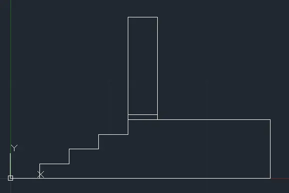
Enter Line Command : L
Line Specify the first point : 0,0
Line Specify the next point or [Undo] : 0.15 (Move mouse in Downward Direction)
Line Specify the next point or [Undo] : 1.15 (Move mouse in Right Direction & Press esc.)
Now Figure :
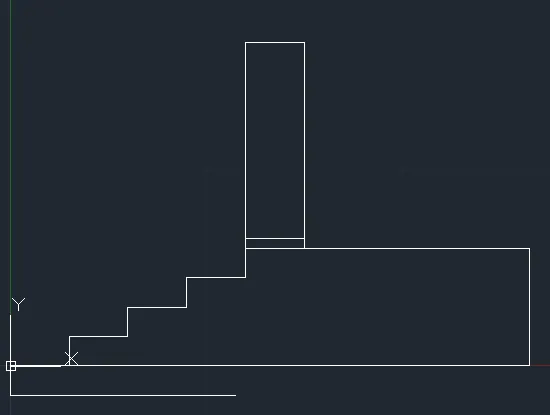
Enter Line Command : L
Line Specify the first point : 1.15,0
Line Specify the next point or [Undo] : 0.40 (Move mouse in Downward Direction)
Line Specify the next point or [Undo] : 0.05 (Move mouse in Left Direction)
Line Specify the next point or [Undo] : 0.40 (Move mouse in Downward Direction)
Line Specify the next point or [Undo] : 0.20 (Move mouse in Left Direction)
Line Specify the next point or [Undo] : 0.25 (Move mouse in Downward Direction & Press esc.)
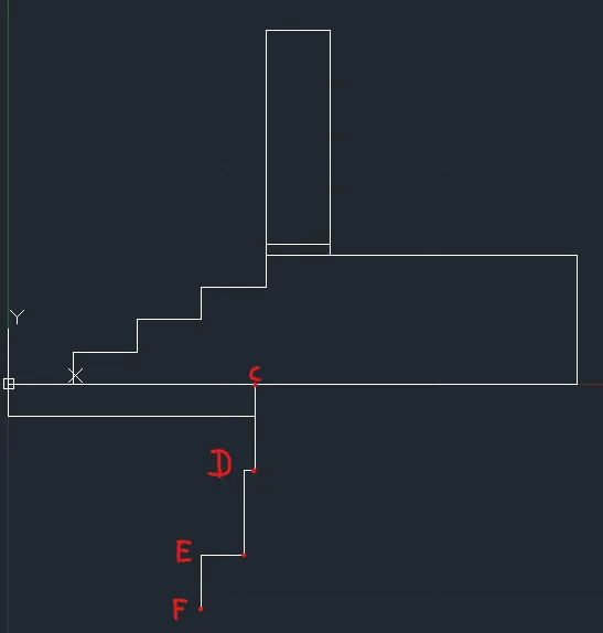
Give Offset Command : o
OFFSET Specify Offset distance : 0.40 (For CD)
Select CD and move the mouse right direction and left click & press esc.
Give Offset Command : o
OFFSET Specify Offset distance : 0.50 (For DE)
Select CD and move the mouse right direction and left click & press esc.
Give Offset Command : o
OFFSET Specify Offset distance : 0.90 (For EF)
Select CD and move the mouse right direction and left click & press esc.
Now, Figure :
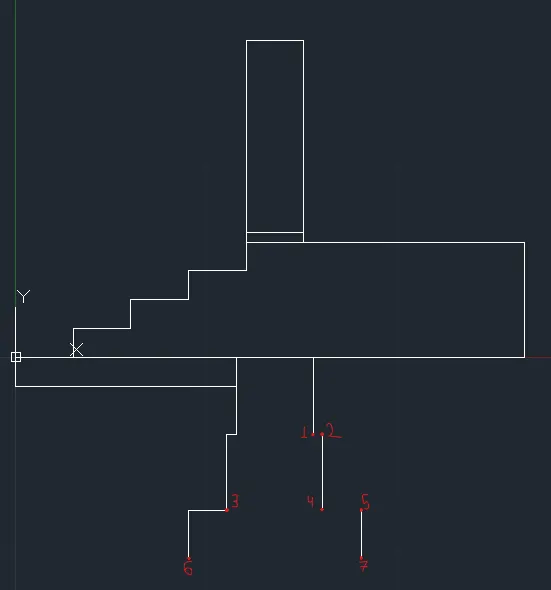
Enter Line Command : L
First click point 1 and then point 2 & press esc.
Enter Line Command : L
First click point 3 and then point 4 & press esc.
Enter Line Command : L
First click point 4 and then point 5 & press esc.
Enter Line Command : L
First click point 6 and then point 7 & press esc.
Now the final Figure :
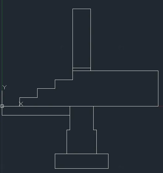
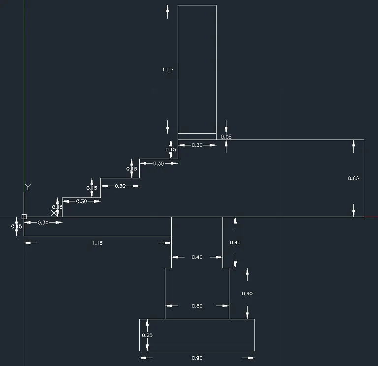
Drawing 2 :
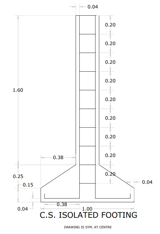
Procedure :
Enter Line Command : L
Line Specify the first point : 0,0
Line Specify the next point or [Undo] : 0.40 (Move mouse in Upward Direction)
Line Specify the next point or [Undo] : 0.38 (Move mouse in Right Direction)
Line Specify the next point or [Undo] : 1,60 (Move mouse in Upward Direction)
Line Specify the next point or [Undo] : 0.04 (Move mouse in Right Direction)
Line Specify the next point or [Undo] : 0.16 (Move mouse in Right Direction)
Line Specify the next point or [Undo] : 0.04 (Move mouse in Right Direction)
Line Specify the next point or [Undo] : 1,60 (Move mouse in Downward Direction)
Line Specify the next point or [Undo] : 0.38 (Move mouse in Right Direction)
Line Specify the next point or [Undo] : 0.40 (Move mouse in Upward Direction)
Line Specify the next point or [Undo] : 0,0
Now Figure :
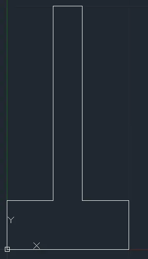
Enter the Chamfer Command : CHAMFER
Select first line or [Undo/Polyline/Distance/Angle/Trim/mEthod/Multiple]:
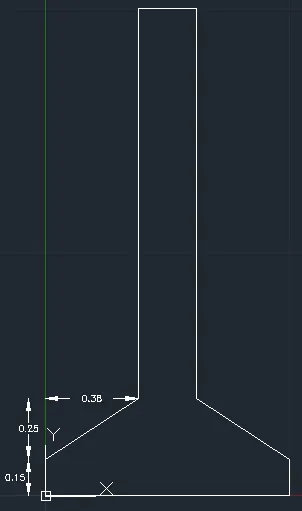
Select second line or shift-select to apply corner or [Distance/Angle/Method]: d Specify first chamfer distance <0>: 0.25 Specify second chamfer distance <0>: 0.38
Select second line or shift-select to apply corner or [Distance/Angle/Method]: (Press esc.)
Now Figure :
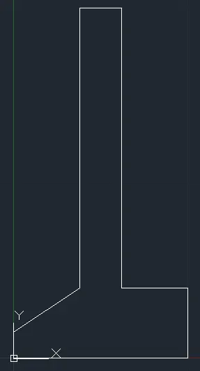
Now applying same command for opposite side,
Enter the Chamfer Command : CHAMFER
Select first line or [Undo/Polyline/Distance/Angle/Trim/mEthod/Multiple]:(Select the vertical line by left click)
Select second line or shift-select to apply corner or [Distance/Angle/Method]:(Select the Horizontal line by left click)
Now Figure :
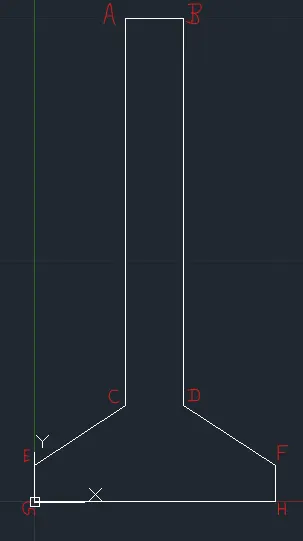
Enter command offset : o
Specify offset distance or [Through/Erase/Layer] : 0.04
Select object to offset or [Exit/Undo] : (Select line EG)
Specify point on side to offset or [Exit/Multiple/Undo] : (move mouse in right direction and left click)
Select object to offset or [Exit/Undo] : (Select line GH)
Specify point on side to offset or [Exit/Multiple/Undo] : (move mouse in Upward direction and left click)
Select object to offset or [Exit/Undo] :(Select line AC)
Specify point on side to offset or [Exit/Multiple/Undo] : (move mouse in right direction and left click)
Select object to offset or [Exit/Undo] : Press esc.
Now Figure :
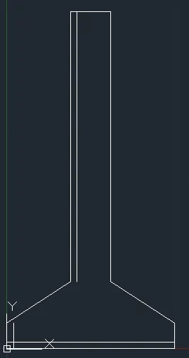
Enter Fillet Command : F
Select first object or [Undo/Polyline/Radius/Trim/Multiple]: (Select offset of EG)
Select second object or shift-select to apply corner or [Radius]: (Select offset of GH)
Enter Fillet Command : F
Select first object or [Undo/Polyline/Radius/Trim/Multiple]: (Select offset of GH)
Select second object or shift-select to apply corner or [Radius]: (Select offset of AC).
Now, Figure :
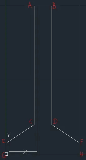
Enter command offset : o
Specify offset distance or [Through/Erase/Layer] : 0.04
Select object to offset or [Exit/Undo] : (Select line FH)
Specify point on side to offset or [Exit/Multiple/Undo] : (move mouse in Left direction and left click)
Select object to offset or [Exit/Undo] : (Select line GH)
Specify point on side to offset or [Exit/Multiple/Undo] : (move mouse in Upward direction and left click)
Select object to offset or [Exit/Undo] :(Select line BD)
Specify point on side to offset or [Exit/Multiple/Undo] : (move mouse in Left direction and left click)
Select object to offset or [Exit/Undo] : Press esc.
Now Figure :
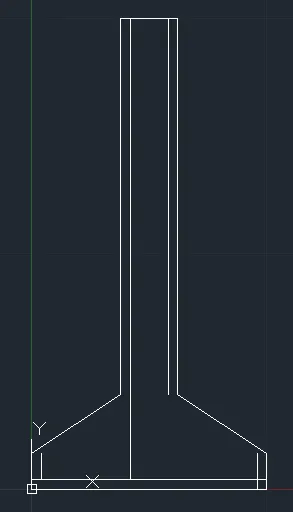
Enter Fillet Command : F
Select first object or [Undo/Polyline/Radius/Trim/Multiple]: (Select offset of FH)
Select second object or shift-select to apply corner or [Radius]: (Select offset of GH)
Enter Fillet Command : F
Select first object or [Undo/Polyline/Radius/Trim/Multiple]: (Select offset of GH)
Select second object or shift-select to apply corner or [Radius]: (Select offset of BD).
Now, Figure :
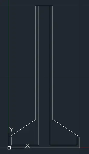
Select the top line between point A & B
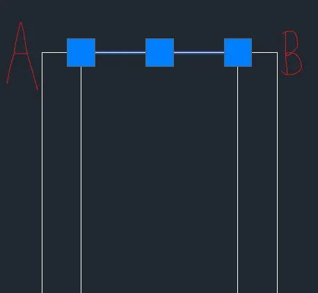
Enter Copy Command : co
Specify base point or [Displacement/mOde] : o (for mode) Enter a copy mode option [Single/Multiple] : m
Specify base point or [Displacement/mOde] : (Click on the one end of the line)
Specify second point or [Array] : a (For Array)
Enter number of items to array: 10
Specify second point or [Fit]: 0.20
Specify second point or [Array/Exit/Undo] : e
Noe Figure :
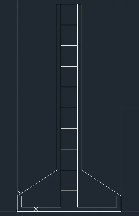
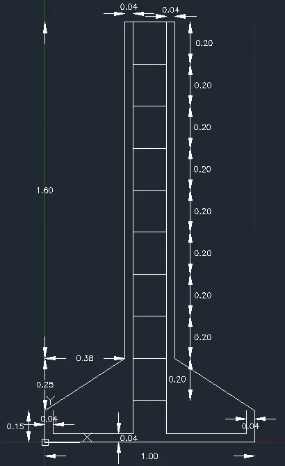
Final Figure with Dimensions :
Drawing 3 :
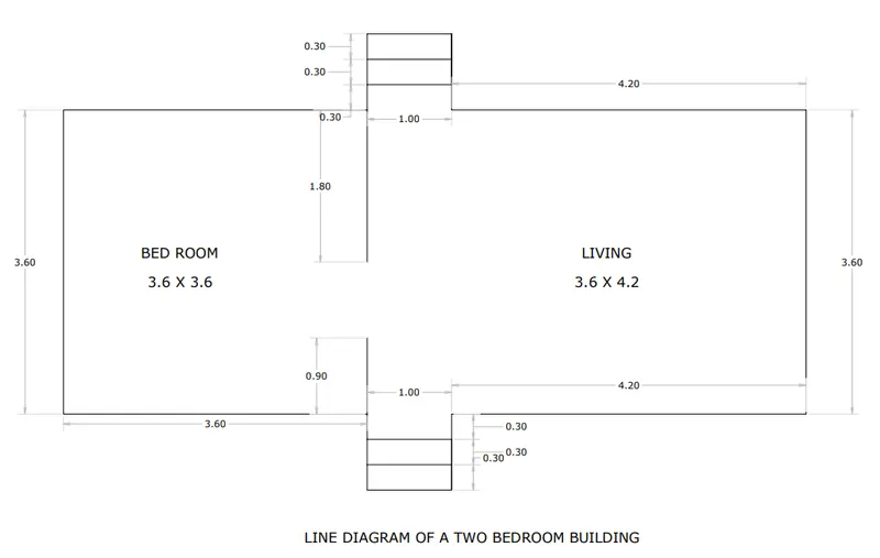
Procedure :
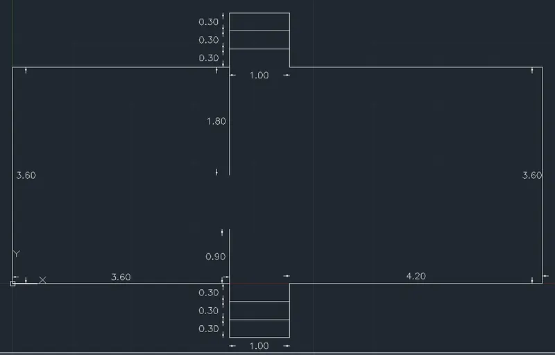
Enter Line Command : L
Line Specify the first point : 0,0
Line Specify the next point or [Undo] : 3.60 (Move mouse in Right Direction)
Line Specify the next point or [Undo] : 0.90 (Move mouse in Downward Direction)
Line Specify the next point or [Undo] : 1 (Move mouse in Right Direction)
Line Specify the next point or [Undo] : 0.90 (Move mouse in Upward Direction)
Line Specify the next point or [Undo] : 4.20 (Move mouse in Right Direction)
Line Specify the next point or [Undo] : 3.60 (Move mouse in Upward Direction)
Line Specify the next point or [Undo] : 4.20 (Move mouse in Left Direction)
Line Specify the next point or [Undo] : 0.90 (Move mouse in Upward Direction)
Line Specify the next point or [Undo] : 1 (Move mouse in Left Direction)
Line Specify the next point or [Undo] : 0.90 (Move mouse in Downward Direction)
Line Specify the next point or [Undo] : 3.60 (Move mouse in Left Direction)
Specify next point or [Close/Undo]: c
Now Figure :
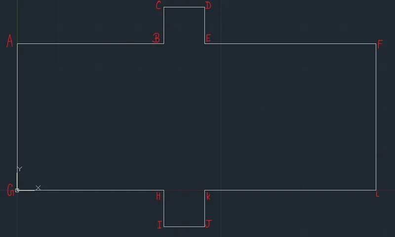
Enter Line Command : L
Line Specify the first point : Left Click the H point or (3.60,0)
Line Specify the next point or [Undo] : 0.90 (Move mouse in Upward Direction)
Press esc.
Enter Line Command : L
Line Specify the first point : Left Click the B point or (3.60,3.60)
Line Specify the next point or [Undo] : 1.80 (Move mouse in Downward Direction)
Press esc.
Enter offset command : o
Specify offset distance or [Through/Erase/Layer] <0>: 0.30
Select object to offset or [Exit/Undo] :(Select line CD)
Specify point on side to offset or [Exit/Multiple/Undo] :(Move mouse downward and left click)
Select object to offset or [Exit/Undo] :(Select new offset line of CD)
Specify point on side to offset or [Exit/Multiple/Undo] :(Move mouse downward and left click)
Select object to offset or [Exit/Undo] :(Select line IJ)
Specify point on side to offset or [Exit/Multiple/Undo] :(Move mouse Upward and left click)
Select object to offset or [Exit/Undo] :(Select new offset line of IJ)
Specify point on side to offset or [Exit/Multiple/Undo] :(Move mouse Upward and left click)
Select object to offset or [Exit/Undo] : Press esc.
Now, Figure :
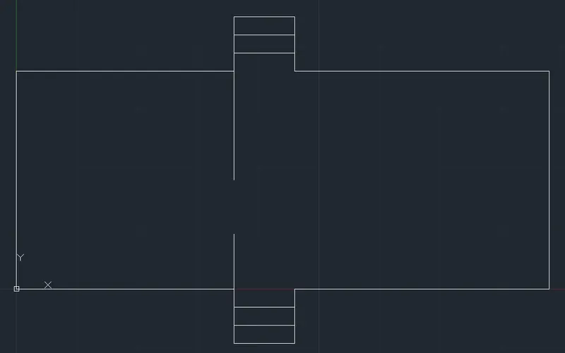
Figure with Dimensions :
Drawing 4 :
Procedure :
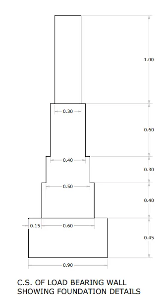
Enter Line Command : L
Line Specify the first point : 0,0
Line Specify the next point or [Undo] : 0.45 (Move mouse in Upward Direction)
Line Specify the next point or [Undo] : 0.15 (Move mouse in Right Direction)
Line Specify the next point or [Undo] : 0.40 (Move mouse in Upward Direction)
Line Specify the next point or [Undo] : 0.05 (Move mouse in Right Direction)
Line Specify the next point or [Undo] : 0.30 (Move mouse in Upward Direction)
Line Specify the next point or [Undo] : 0.05 (Move mouse in Right Direction)
Line Specify the next point or [Undo] : 0.60 (Move mouse in Upward Direction)
Line Specify the next point or [Undo] : 0.05 (Move mouse in Right Direction)
Line Specify the next point or [Undo] : 1 (Move mouse in Upward Direction)
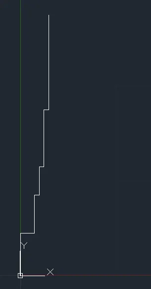
Now Figure :
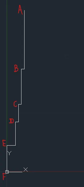
Enter Offset command : o
Specify offset distance or [Through/Erase/Layer] <0>: 0.90
Select object to offset or [Exit/Undo] : (Select line EF)
Specify point on side to offset or [Exit/Multiple/Undo] :(Move mouse in right direction and left click & press esc.)
Enter Offset command : o
Specify offset distance or [Through/Erase/Layer] <1>: 0.60
Select object to offset or [Exit/Undo] :(Select line DE)
Specify point on side to offset or [Exit/Multiple/Undo] :(Move mouse in right direction and left click & press esc.)
Enter Offset command : o
Specify offset distance or [Through/Erase/Layer] <1>: 0.50
Select object to offset or [Exit/Undo] :(Select line CD)
Specify point on side to offset or [Exit/Multiple/Undo] :(Move mouse in right direction and left click & press esc.)
Enter Offset command : o
Specify offset distance or [Through/Erase/Layer] <1>: 0.40
Select object to offset or [Exit/Undo] :(Select Line BC)
Specify point on side to offset or [Exit/Multiple/Undo] :(Move mouse in right direction and left click & press esc.)
Enter Offset command : oSpecify offset distance or [Through/Erase/Layer] <0>: 0.30
Select object to offset or [Exit/Undo] :(Select line AB)
Specify point on side to offset or [Exit/Multiple/Undo] :(Move mouse in right direction and left click & press esc.)
Now Figure :
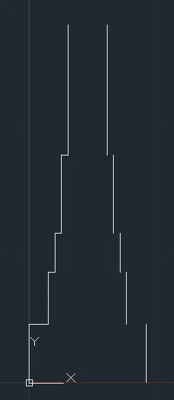
Now Join the Points as per the given figure using Line Command and clicking the points directly and the final figure will be :
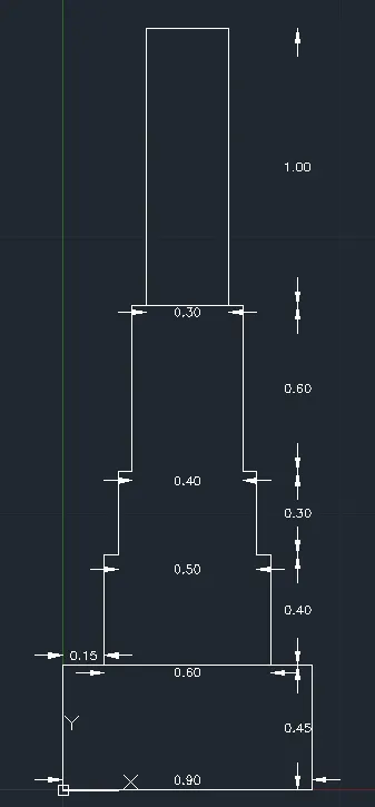
Drawing 5 :
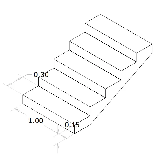
Procedure :
Enter ISODRAFT Command : ISODRAFT
Enter an option [Orthographic/isoplane Left/isoplane Top/isoplane Right] <isoplane Left>:L
Enter Line Command : L
Line Specify first point: 0,0
Line Specify next point or [Undo]: 1 (Move Mouse in right-downward direction)
Line Specify next point or [Undo]: 0.15 (Move Mouse in Right-upward Direction)
Line Specify next point or [Close/Undo]: 1 (Move Mouse in Left-Upward Direction)
Line Specify next point or [Close/Undo]: 0,0
Line Specify next point or [Close/Undo]: Press esc.
Now Figure :
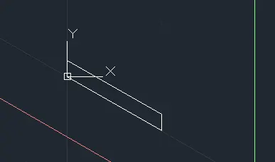
Press F5 for <Isoplane Top>
Enter Line Command : L
Line Specify first point: 0,0.15
Line Specify next point or [Undo]: 0.30 (Move mouse in Right-Upward direction)
Line Specify next point or [Undo]: 1 (Move mouse in right-downward direction)
Line Specify next point or [Close/Undo]: 0.30 (Move mouse in Left-downward direction)
Line Specify next point or [Close/Undo]: Press esc
Now Figure :
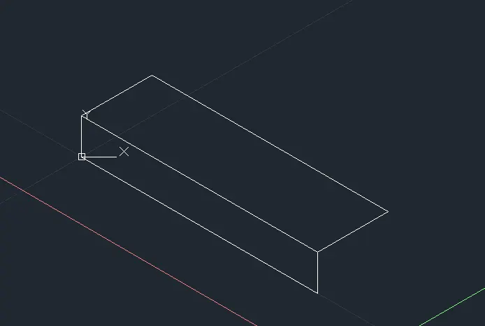
Enter Copy command : co
Select line AB and take Point A Reference point and Click the end Point 0.15 below.
Now Figure :
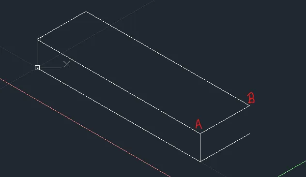
Press F5 <Isoplane Right>
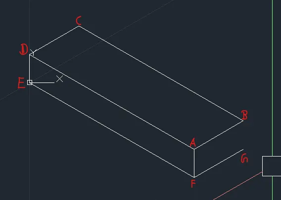
Select Line AB,BC,CD,AD,DE,AF
Enter Copy Command : co
Specify base point or [Displacement/mOde] <Displacement>: o (For Mode)Enter a copy mode option [Single/Multiple] <Multiple>: m
Specify base point or [Displacement/mOde] <Displacement>: (Left Click the E point)
Specify second point or [Array] <use first point as displacement>: a
Enter number of items to array: 5
Specify second point or [Fit]: (Left Click the C point)
Specify second point or [Array/Exit/Undo] <Exit>: Press Esc.
Now Figure :
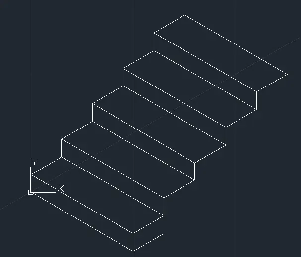
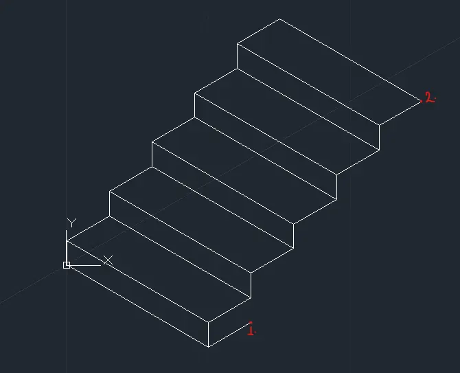
Enter line Command : L
Line Specify first point: Left click the point 2
Line Specify next point or [Undo]: 0.15 (Move mouse in Downward direction)
press esc.
Now Figure :
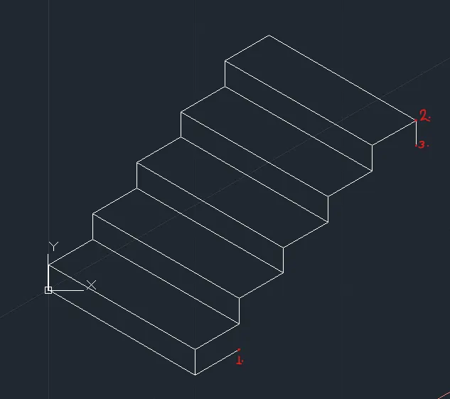
Enter line Command : L
Line Specify first point: Left click the point 3
Line Specify next point or [Undo]: Left click the point 1
press esc.
Now Final Figure :
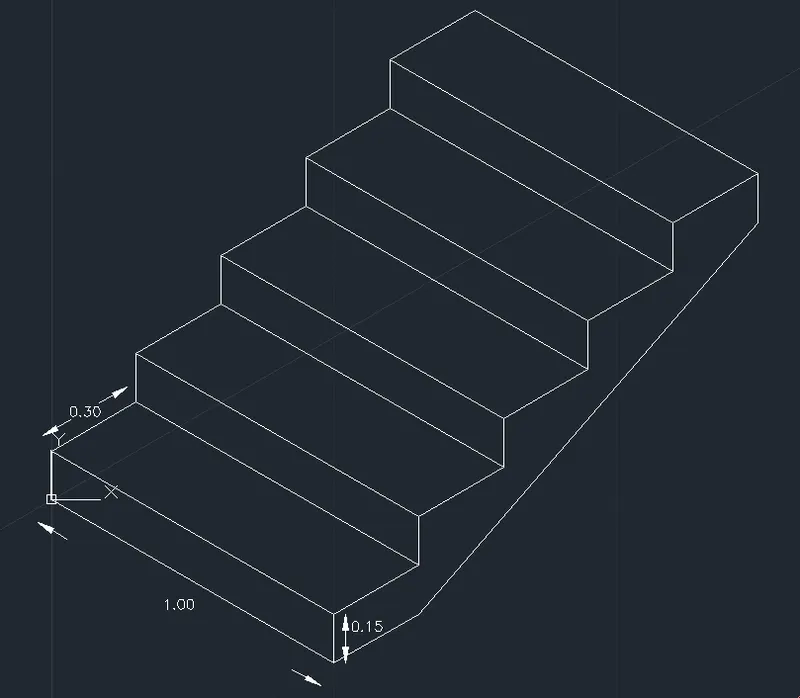
Drawing 6 :
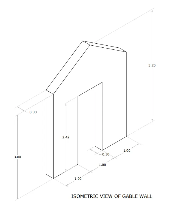
Procedure :
Enter ISODRAFT Command : ISODRAFT
Enter an option [Orthographic/isoplane Left/isoplane Top/isoplane Right] <isoplane Left>:L
Enter Line Command : L
Line Specify first point: 0,0
Line Specify next point or [Undo]: 0.30 (Move Mouse in right-downward direction)
Line Specify next point or [Undo]: 3.25 (Move Mouse in upward Direction)
Line Specify next point or [Close/Undo]: 0.30 (Move Mouse in Left-Upward Direction)
Line Specify next point or [Close/Undo]: 0,0
Now Figure :
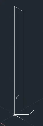
Press esc.
Press F5 <Isoplane Top>
Again Press F5 <Isoplane Right>

Select the line in above figure and Enter copy command : co
Specify base point or [Displacement/mOde] <Displacement>: (Left click the bottom of the selected line)
Specify second point or [Array] <use first point as displacement>: a
Enter number of items to array: 4
Specify second point or [Fit]: 1
Specify second point or [Array/Exit/Undo] <Exit>: e
Now Figure :
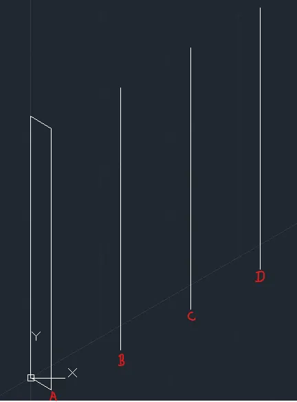
Enter line command : L
Join AB then BC then CD and press esc.
Select Line BC :
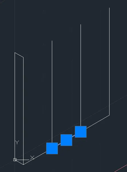
Enter Move Command : m
Specify base point or [Displacement] <Displacement>: (Take Point B)
Specify second point or <use first point as displacement>: 2.42
Now Figure :
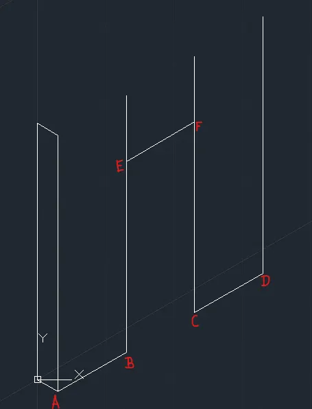
Now Enter Fillet Command : FILLET
Select first object or [Undo/Polyline/Radius/Trim/Multiple]: (Select line BE)
Select second object or shift-select to apply corner or [Radius]: (Select Line EF)
Now Enter Fillet Command : FILLET
Select first object or [Undo/Polyline/Radius/Trim/Multiple]: (Select Line EF)
Select second object or shift-select to apply corner or [Radius]: (Select Line FC)
Now Figure :
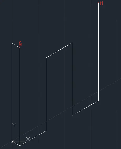
Enter Line command : L
Join G and H point & press esc.
Enter Erase command : e
Select the adjecent line to GH and press enter
Now figure :
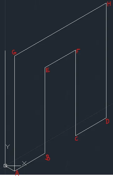
Enter the Chamfer Command : CHAMFER
Select first line or [Undo/Polyline/Distance/Angle/Trim/mEthod/Multiple]: (Select Line AG)
Select second line or shift-select to apply corner or [Distance/Angle/Method]: d Specify first chamfer distance <0>: 0.25 Specify second chamfer distance <0>: 1.5
Select second line or shift-select to apply corner or [Distance/Angle/Method]: (Select Line GH)
Again Enter the Chamfer Command : CHAMFER
Select first line or [Undo/Polyline/Distance/Angle/Trim/mEthod/Multiple]: (Select Line DH)
Select second line or shift-select to apply corner or [Distance/Angle/Method]: d Specify first chamfer distance <0>: 0.25 Specify second chamfer distance <0>: 1.5
Select second line or shift-select to apply corner or [Distance/Angle/Method]: (Select Line GH)
Now Figure :
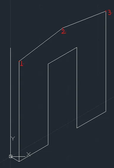
Press F5 <Isoplane Left>
Enter Line command : L
Line Specify first point: (Left click point 1)
Line Specify next point or [Undo]: 0.30 (Move Mouse in Left-Upward direction) & press esc.
Enter Line command : L
Line Specify first point: (Left click point 2)
Line Specify next point or [Undo]: 0.30 (Move Mouse in Left-Upward direction) & press esc.
Enter Line command : L
Line Specify first point: (Left click point 3)
Line Specify next point or [Undo]: 0.30 (Move Mouse in Left-Upward direction) & press esc.
Now Figure :
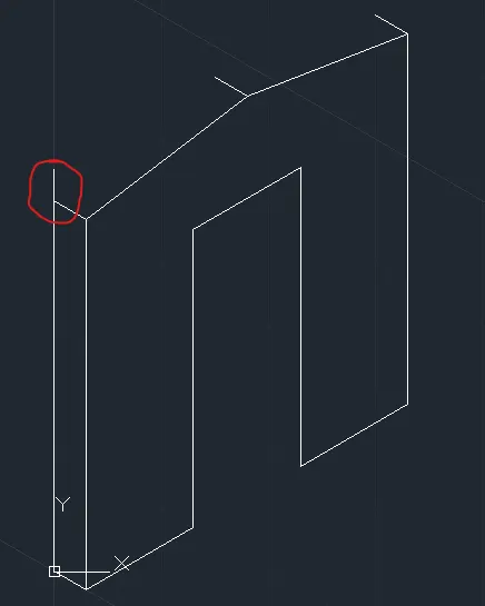
Fillet the marked line
Enter Fillet command : F
Select both line and enter
now figure :
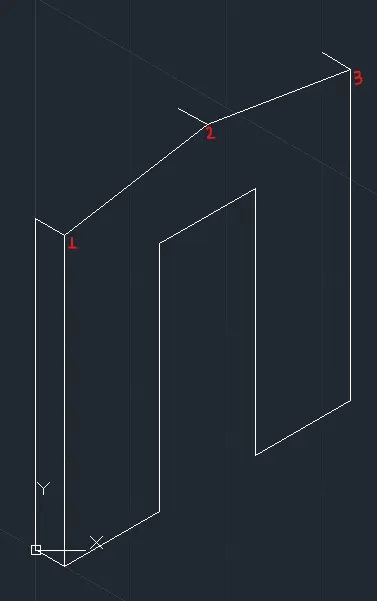
Select Line 1-2 & Line 2-3
Enter copy command : co
Specify base point or [Displacement/mOde] <Displacement>: Left click the pint 1
Specify second point or [Array] <use first point as displacement>: 0.30
Specify second point or [Array/Exit/Undo] <Exit>: e
Now Figure :
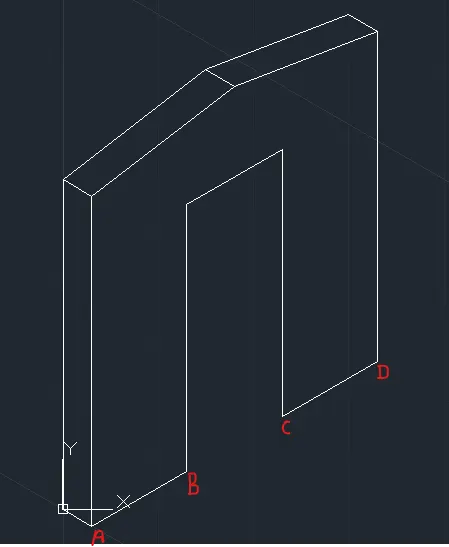
Enter Line command : L
Line Specify first point: (Left click point C)
Line Specify next point or [Undo]: 0.30 (Move Mouse in Left-Upward direction)
Line Specify next point or [Undo]: (Move Mouse in Upward direction till the above line and click the point) & press esc.
Now, Final Figure :