Drafting of various geometries using Chamfer, Fillet tool in AutoCad
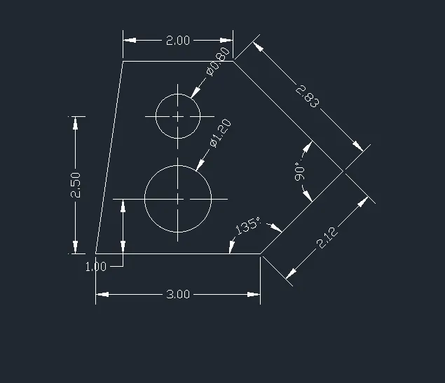
1. Aim: To create the Geometries using chamfer and fillet command in the Auto cad using decimal system.
Procedure :
- Click on new File and create the new template for potting the drawing
- Now enter units (un) command and select the decimal system in the units and also set the precision of the units and insertion scale to either MILLIMETRS or METERS click on ok.
- Now enter Dimstyle command and set the primary units in the decimal system and set the precision of the units and insertion scale and click on ok, Now the template is ready for drawing in the decimal system.
- Click on polar settings option and click on track settings and select relative last segment and click on ok.
- Enter poly line 'pl' command and select the point and enter the distance as 3 and now place the cursor in the up ward direction and place the cursor in the position till the tracker shows the specific angle requiired for the line and enter the distance and again place the cursor in the forward line direction and place it in the position until we require specific angle and enter the distance.
- Now the circular holes are drawn using the circle command.
- Now select Line command and specify the left corner but don't click on the point it used for tracking in the rightside direction and enter the distance as 1.5 and it tracks a point on the bottom line and now place the cursor in the vertical direction and enter the distance 1.0and it meets at a point and it will the centre of the circle.
- Select the circle command and click on the centre and enter diameter as 1.2, Then the circle with a diameter of 1.2 units is formed.
- Similarly repeat the procedure again just by changing the units and draw the second circle.
- Now uing the dimlinear and dim radius the dimensions of the geometric figure is measured.
- The resultant figure is obtained as shown below.
2.Aim: To create the Geometries using chamfer and fillet command in the Auto cad using Architectural system.
Procedure :
- Click on new File and create the new template for potting the drawing.
- Now enter units (un) command and select the architectural system in the units and also set the precision of the units and insertion scale to Inches click on ok.
- Now enter Dimstyle command and set the primary units in the architectural system and set the precision of the units and insertion scale to inches and click on ok, Now the template is ready for drawing in the decimal system.
- Click on polar settings option and click on track settings and select relative last segment and click on ok.
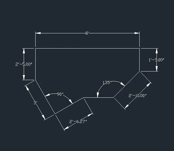
- Enter poly line 'pl' command and select the point and enter the distance as 2'5" in the upward direction and now place the cursor in the right side direction and enter the distance as 8' and place the cursor in the down ward direction and enter 1'9"and place the cursor in the position till the tracker shows the specific angle i.e 135 degeres requiired for the line and enter the distance and again place the cursor in the left side line direction and place it in the position until we require specific angle and enter the distance.
- When the initial and final point is same then we can also use Close 'c' command.
- Now uing the dimlinear and dim radius the dimensions of the geometric figure is measured.
- The resultant figure is obtained as shown below.
3. Aim: To create the Geometries using chamfer and fillet command in the Auto cad using Engineering system.
Procedure :
- Click on new File and create the new template for potting the drawing
- Now enter units (un) command and select the decimal system in the units and also set the precision of the units and insertion scale to inches click on ok.
- Now enter Dimstyle command and set the primary units in the decimal system and set the precision of the units and insertion scale and click on ok, Now the template is ready for drawing in the decimal system.
- Click on polar settings option and click on track settings and select relative last segment and click on ok.
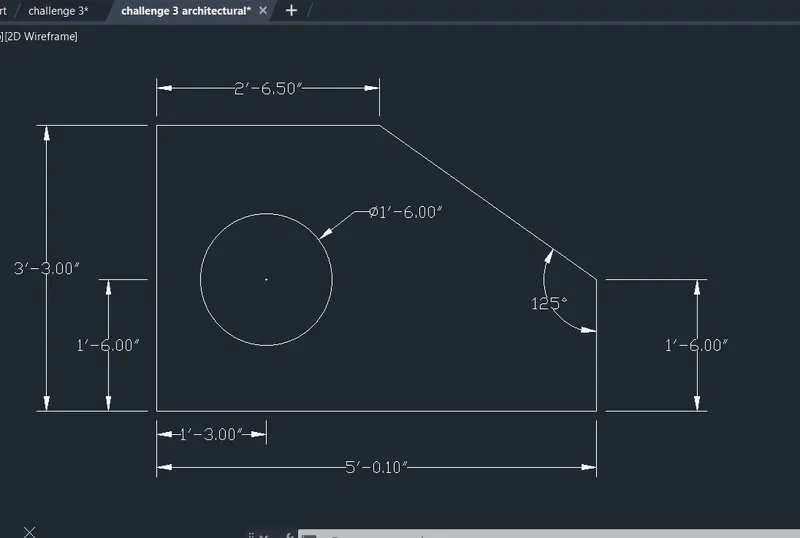
- Enter poly line 'pl' command and select the point and enter the distance as 3'3" in the upward direction and now place the cursor in the right side direction in horizontal position and enter the distance as 2'6.5"and press enter.Now again enter the poly line command the cursor in the starting point and in right side direction and enter the distance as 5'0.6"and place the cursor in the upside and enter the distance as 1'6" and presss enter .
- Now place the cursor in the upward with thangle 125degrees and join with the above line and the geometry boundary is formed .
- Now the circular holes are drawn using the circle command.
- Now select Line command and specify the left corner but don't click on the point it used for tracking in the rightside direction and enter the distance as 1'3" and it tracks a point on the bottom line and now place the cursor in the vertical direction and enter the distance 1'6"and it meets at a point and it will the centre of the circle.
- Select the circle command and click on the centre and enter diameter as 1'6", Then the circle with a diameter of 1'6" units is formed.
- Now uing the dimlinear and dim radius the dimensions of the geometric figure is measured.
- The resultant figure is obtained as shown below.
4. Aim: To create the Geometries using chamfer and fillet command in the Auto cad using decimal system.
Procedure :
- Click on new File and create the new template for potting the drawing
- Now enter units (un) command and select the decimal system in the units and also set the precision of the units and insertion scale to either MILLIMETRS or METERS click on ok.
- Now enter Dimstyle command and set the primary units in the decimal system and set the precision of the units and insertion scale and click on ok, Now the template is ready for drawing in the decimal system.
- Click on ortho mode option to get the tracking in 90,180,270,360 only for better convienience.
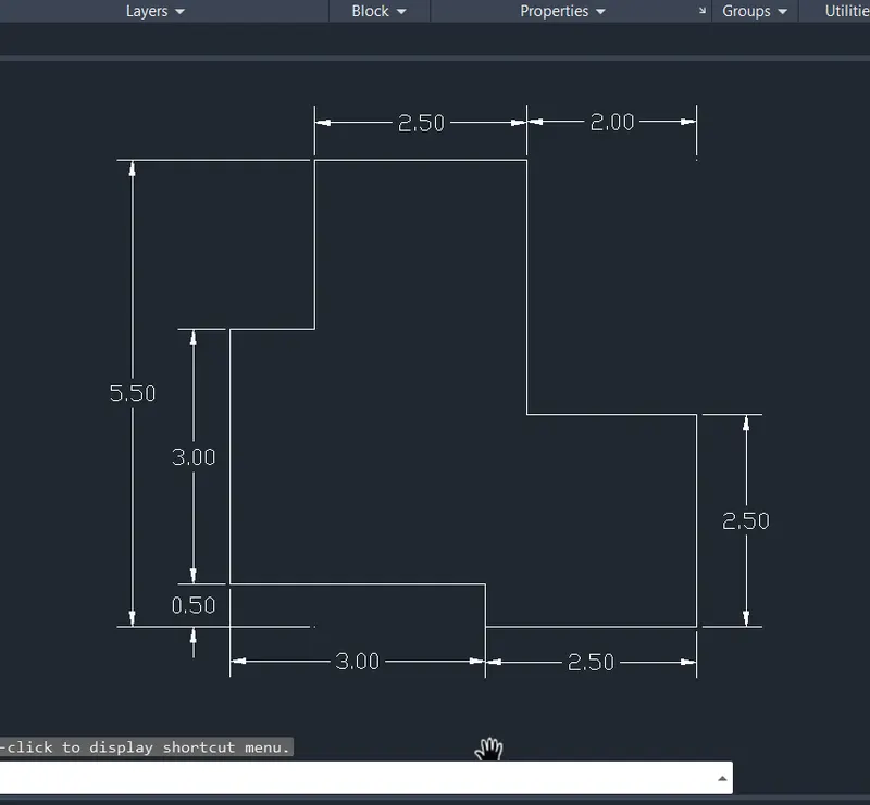
- Enter poly line 'pl' command and select the point and place cursor in the right side and enter the distance as 3 and now place the cursor in the down ward direction and eneter the distance as 0.5and click on enter and place the cursor in the right side again in horizontal position and enter the distance 2.5 and press enter.Here the geometric edges are perpendicular to each other so it is better to draw ortho mode.
- Continue with the poly line command till the last point and use close command if required.
- Now uing the dimlinear and dim radius the dimensions of the geometric figure is measured.
- The resultant figure is obtained as shown below.
5. Aim: To create the Geometries using chamfer and fillet command in the Auto cad using decimal system.
Procedure :
- Click on new File and create the new template for potting the drawing
- Now enter units (un) command and select the decimal system in the units and also set the precision of the units and insertion scale to either MILLIMETRS or METERS click on ok.
- Now enter Dimstyle command and set the primary units in the decimal system and set the precision of the units and insertion scale and click on ok, Now the template is ready for drawing in the decimal system.
- Click on ortho mode option.
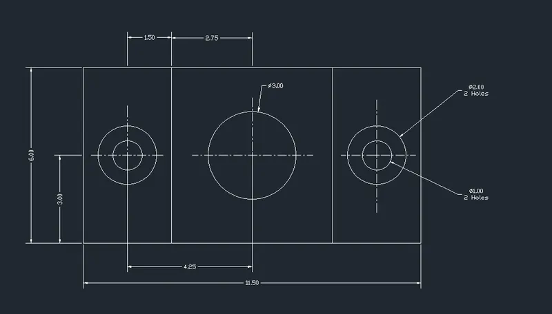
- Enter line 'l' command and form a rectangle with ortho option with length as 11.5 and width as 6.
- Now using the off set command plot the offset lines to with an offset distances of 3 for the horizontal line and offset distamnces of 1.5,3 and 4.75 for the vertical lines of the rectangle to get the center points of the circle.
- Now the circular holes are drawn using the circle command.
- Enter circle command and plot the two number of circles on each center point obtained at the end and draw the with radii of 1&2units.
- Now again select the circle cpommand and plot the circle at the middle centre point obtained and draw the circle at with radius of 3units .
- Now change the centerlines of the circles using 'BY LAYER' option.The line mode is changed to center and the scale is adjusted to apprpraite size .
- Now uing the dimlinear and dim radius the dimensions of the geometric figure is measured.
- The resultant figure is obtained as shown below.
6. Aim: To create the Geometries using chamfer and fillet command in the Auto cad using Engineering system.
Procedure :
- Click on new File and create the new template for potting the drawing
- Now enter units (un) command and select the decimal system in the units and also set the precision of the units and insertion scale to inches click on ok.
- Now enter Dimstyle command and set the primary units in the decimal system and set the precision of the units and insertion scale and click on ok, Now the template is ready for drawing in the decimal system.
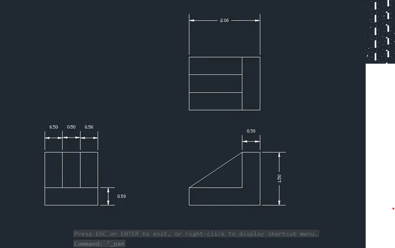
- The given geometry consists of orthographic views, i.e Front view, side view, Top view.
- These view can be drawn easily with line or poly line command and offset command.
- After drawing the one view the other views can be projected with the help of construction lines.
- Enter the line command and enter the distances with respect to the direction and inclination and plot the lines of the view.
- Now using the construction lines the edges of a view are projected or prolonged to get to to know the position of the other view which may be side or top view.
- Enter the line command and the distances with respect to the front view is entered and the lines are drawn in between the construction lines and the top or side view is formed.
- Now using the trim command the unwanted lines are trimmed which may be conastuction lines also.
- Now uing the dimlinearcommand dimensions of the geometric figure is measured.
- The resultant figure is obtained as shown below.
7. Aim: To create the Geometries using chamfer and fillet command in the Auto cad using decimal system.
Procedure :
- Click on new File and create the new template for potting the drawing
- Now enter units (un) command and select the decimal system in the units and also set the precision of the units and insertion scale to either MILLIMETRS or METERS click on ok.
- Now enter Dimstyle command and set the primary units in the decimal system and set the precision of the units and insertion scale and click on ok, Now the template is ready for drawing in the decimal system.
- Click on ortho mode option as the lines in the geometry are perpendicular to each other.
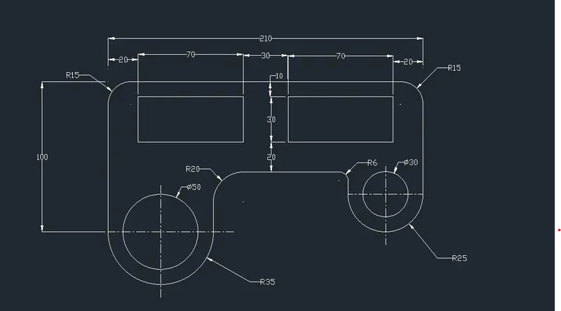
- Eneter the line command,select the point and place the cursor in the upward and enter the distance as 100 and place the cursor in the horizontal direction enter the distance as 210 and place the cursor downward enter distance 75 press enter.
- Now enter the line command draw the lines at the end points in horizontal direction with the length of 70 and 50 to get the semi circles and center point for the circles.
- Now select arc commad, select start end, radius option click on start point,end point and enter radius and draw the arcs on both sides with radii 0f 35 and 25.
- Now select the circle command with the cebtre points draw the two circles with diameter of 50 and 30 mm on both the points.
- Now enter the line command and extend the semicircles to a certaim length and join those two lines with the offset line from the the top with the offset distance 60 units from the top.
- Now enter the line command and track the line 20from the left side top edge and 10units to th bottom of the top line plot a rectangle of size of length70 and width 30.
- Enter copy command copy the rectangle to the horizontal direction at distance of 30 units between them.
- Enter fillet command and enter the radius of the fillet and select the both ends of the lines and forms a curve shape with specific radius.
- Now using trim command trim the extra lines which are not necessary.
- Now change the centerlines of the circles using 'BY LAYER' option.The line mode is changed to center and the scale is adjusted to apprpraite size .
- Now uing the dimlinear and dim radius the dimensions of the geometric figure is measured.
- The resultant figure is obtained as shown below.
8. Aim: To create the Geometries using chamfer and fillet command in the Auto cad using decimal system.
Procedure :
- Click on new File and create the new template for potting the drawing
- Now enter units (un) command and select the decimal system in the units and also set the precision of the units and insertion scale to millimeters or meters click on ok.
- Now enter Dimstyle command and set the primary units in the decimal system and set the precision of the units and insertion scale and click on ok, Now the template is ready for drawing in the decimal system.
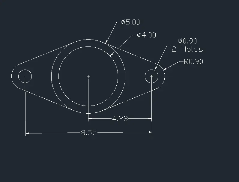
- Enter line command and draw a line of length 8.55.the end points will be the centre of the circle.
- Now enter circle command and draw 2 no of circles at theeach extreme end points of line with radius of 0.9 and diameter 0.9 on both sides of the line.
- Now enter the circle command and select the midpoint on the line draw two number of circles with radii of 4&5.
- Now select the line command and enter tan and select point on the circle on the end and enter tan and select crcle on the centre and press enter it forms a tangent .
- Now repeat on all the four sides and creates tangents.
- Now using trim command trim the line between the centres and the circular portions on top and bottom.
- Now uing the dimlinear and dim radius the dimensions of the geometric figure is measured.
- The resultant figure is obtained as shown below.
9. Aim: To create the Geometries using chamfer and fillet command in the Auto cad using Engineering system.
Procedure :
- Click on new File and create the new template for potting the drawing
- Now enter units (un) command and select the decimal system in the units and also set the precision of the units and insertion scale to inches click on ok.
- Now enter Dimstyle command and set the primary units in the decimal system and set the precision of the units and insertion scale and click on ok, Now the template is ready for drawing in the decimal system.
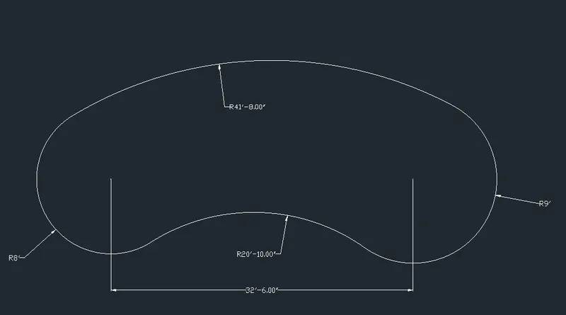
- Enter line command and draw a line of length 32'6".the end points will be the centre of the circle.
- Now enter circle command and draw 2 no of circles at the extreme end points of line with radii of 8' and 9'
- Now select the circle command with tan tan radius and select the two cicles at the bottom and enetr the radius as 20'10".
- Now repeat the same with the radius as 41'8" with the tangent points as extreme outside of the circles.
- Now using trim command trim the line between the centres and the circular portions on top and bottom.
- Now uing the dimlinear and dim radius the dimensions of the geometric figure is measured.
- The resultant figure is obtained as shown below.
10. Aim: To create the Geometries using chamfer and fillet command in the Auto cad using Engineering system.
Procedure :
- Click on new File and create the new template for potting the drawing
- Now enter units (un) command and select the decimal system in the units and also set the precision of the units and insertion scale to inches click on ok.
- Now enter Dimstyle command and set the primary units in the decimal system and set the precision of the units and insertion scale and click on ok, Now the template is ready for drawing in the decimal system.
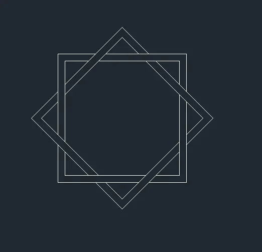
- Enter l rectangular command and enter the specified dimensions of the rectangle and draw the rectangle with equal length and width.
- Now using offset command another rectangle is plotted eith a small offset distance .
- Now enter the rotate command the rectangle is selected and press enter and click on the base point and select copy option and enter the rotation angle as 45 degrees and press enter .The rectangle is rotated in the 45degrees .
- Now using the trim command trim the portions of the rectangle where it required.
- Now uing the dimlinear and dim radius the dimensions of the geometric figure is measured.
- The resultant figure is obtained as shown below.
11. Aim: To create the Geometries using chamfer and fillet command in the Auto cad using Engineering system.
Procedure :
- Click on new File and create the new template for potting the drawing
- Now enter units (un) command and select the decimal system in the units and also set the precision of the units and insertion scale to inches click on ok.
- Now enter Dimstyle command and set the primary units in the decimal system and set the precision of the units and insertion scale and click on ok, Now the template is ready for drawing in the decimal system.
- Click on the ortho mode as the most of the lines are perpendicular to each other.
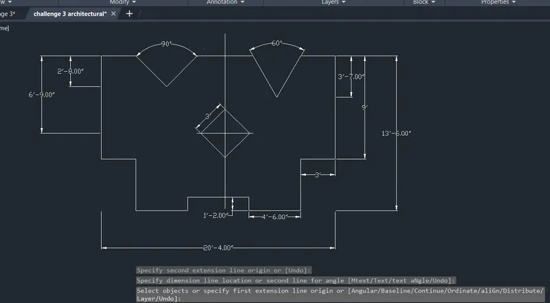
- Enter poly line 'pl' command and select the point and enter the distances as required and draw the lines in the specified directions to form the outer perimeter of the geometry except the top line.
- Now using line command draw two lines with a distances of 3' from the top end points of the diagram in horizontal direction.
- Enter the line command and track the points at a distance 2'8" and the 3'7" from the top line.
- Now change the ortho mode into polar tracking and using the line command draw the lines with the angle of 90degrees and 60degrees.
- Now using the midpoint inthe object snap mode centre point is tracked.
- Now enter the polygon command and enter 4 sides and select circumscribed with circle and enter the radius as 1.5'and plot the polygon with the center point.
- Now using rotatae command rotate with respect to center point at a rotation angle of 45 degrees.
- Enter the trim command and trim the unwanted lines.
- Now uing the dimlinear and dim radius the dimensions of the geometric figure is measured.
- The resultant figure is obtained as shown below.