Creating a Floor plan, Footing detail and Isometric view using AutoCad
Aim:To create the cross section of the load bearing wall with spread footing, Column with Isolated footing,Cross section of the load bearing walls, Single line diagran for the double room building and Isometric view of the Stairs and Isometric view of the Gable wall.
Procedure:
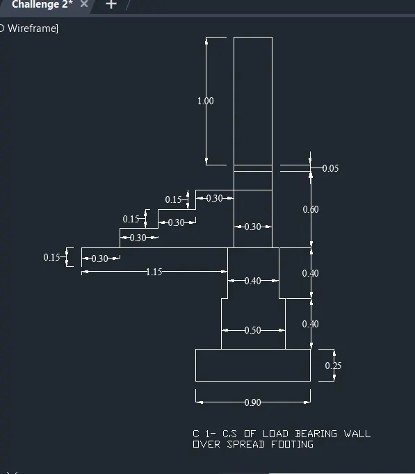
C 1- Cross section of the load bearing wall with spread footing
- Click for the new drawing in the file menu and open new drawing and selet the template according to the units of the drawing either imperial or metric unit and please click on the advance set up and make sure all the setings regarding units,area,angle ,angle measure is all set and the ready the drawing sheet is ready to plot.
- After the advance set up in the drawing, Enter units(UN) command in the command bar and set the type of the units and its precision to the accuracy and click on OK.
- Before plotting it is better to check the dimension style(Dimstyle) co9mmand and click on modify and check the type of units in the primary units option.
- Enter Construction line i.e 'XL' in the command bar and create one horizontal and one vertical construction line andtheir intersection point will be used as the on of the bottom edge of the spread footing.
- Now using Offset command i.e 'O' in the command bar and the vertical offsets are given with appropraite offset distances to the vertical construction line.
- Now using the Trim command,i.e 'Tr' in the command bar and the Horizontal construction line and the vertical construction lines including the offset lines below the horizontal construction is trimmed to clear the unwanted lines in the drawing.
- Now using the offset command, offset lines to the horizontal in the positive Y-axis direction is drawn with respective dimensions of the footings.
- Now using Trim command unwanted lines, i.e lines which are projected outside the footing and the vertical construction and offset lines beyond the specified measurements are trimmed to form the cross section of the load bearing wall with spread footing.
- The steps are plotted using the line command in the ortho mode so that the steps are formed perpendicularlyto each other
- Now using 'Dimlinear' command the dimensions of the footing and the dimensions of the steps are measured.
- The properties of the dimensions can be changed using the 'Dimstyle' command and the properties of dimension line,line type,line weight,Text size and angle etc can be changed from the modify option.
- The result of the Crossection of the load bearing wall with spread footing is obtained as shown below.
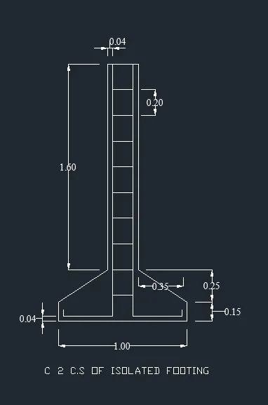
C 2- Cross section of the Isolated footing
- Click for the new drawing in the file menu and open new drawing and selet the template according to the units of the drawing either imperial or metric unit and please click on the advance set up and make sure all the setings regarding units,area,angle ,angle measure is all set and the ready the drawing sheet is ready to plot.
- After the advance set up in the drawing, Enter units(UN) command in the command bar and set the type of the units and its precision to the accuracy and click on OK.
- Before plotting it is better to check the dimension style(Dimstyle) command and click on modify and check the type of units in the primary units option.
- Enter Construction line i.e 'XL' in the command bar and create one horizontal and one vertical construction line andtheir intersection point will be used as the one of the bottom edge of the isolated footing.
- Now using Offset command i.e 'O' in the command bar and the vertical offsets are given with appropraite offset distances to the vertical construction line.
- Now using the Trim command,i.e 'Tr' in the command bar and the Horizontal construction line and the vertical construction lines including the offset lines below the horizontal construction is trimmed to clear the unwanted lines in the drawing.
- Now using the offset command, offset lines with the thickness of the isolated footing to the bottom line are drawn in the positive Y-axis direction.
- Now using Trim command unwanted lines, i.e lines which are projected outside the footing and the vertical construction and offset lines beyond the specified measurements are trimmed to form the cross section of the load bearing wall with spread footing.
- The stirrups in the column are drawn by using either copy command or Offset command. One of the stirrup is drawn at the connection with column and footing and the rest of the stirrups are drawn with copy command or offset command.
- By using copy command the stirrups are copied and placed by entering the spacing of the stirrups as the displacement in the copy command.
- Using the trim command the excess lines are trimmed.
- Now using 'Dimlinear' command the dimensions of the footing is measured.
- The properties of the dimensions can be changed using the 'Dimstyle' command and the properties of dimension line,line type,line weight,Text size and angle etc can be changed from the modify option.
- The result of the Crossection of the isolated footing is obtained as shown below.
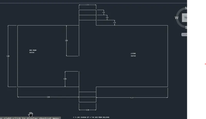
C 3- Line diagram of a two room building
- Click for the new drawing in the file menu and open new drawing and selet the template according to the units of the drawing either imperial or metric unit and please click on the advance set up and make sure all the setings regarding units,area,angle ,angle measure is all set and the ready the drawing sheet is ready to plot.
- After the advance set up in the drawing, Enter units(UN) command in the command bar and set the type of the units and its precision to the accuracy and click on OK.
- Before plotting it is better to check the dimension style(Dimstyle) command and click on modify and check the type of units in the primary units option.
- The given two room building is in the form of rectangle so it can be plotted by using rectangle command or poly line command.
- For this we can use rectangle command,i.e enter 'rec' in the command bar specify the coener point and enter the dimensions of length (3.6+1+4.2) and width (3.6).
- Using the off set command i.e 'o' in the command bar and give the offset distance of 3.6 draw the partition line two divide the rooms
- Use the offset command for the lines representing the length of the building and with off set distance 0.9 and 1.8 the two lines are plotted and using the trim command the lines can be trimmed to form the door opening for the partition wall.
- The partition wall is strecthed on both sides to plot the steps of the building. The line is stretched by using 'GRIPS'.
- The steps can be plotted by using the line command.
- Now using 'Dimlinear' command the dimensions of the room and the dimensions of the steps are measured.
- The properties of the dimensions can be changed using the 'Dimstyle' command and the properties of dimension line,line type,line weight,Text size and angle etc can be changed from the modify option.
- The result of the line diagram of two room building is obtained as shown below.
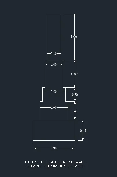
C 4- Cross section of the load bearing wall with foundation details
- Click for the new drawing in the file menu and open new drawing and selet the template according to the units of the drawing either imperial or metric unit and please click on the advance set up and make sure all the setings regarding units,area,angle ,angle measure is all set and the ready the drawing sheet is ready to plot.
- After the advance set up in the drawing, Enter units(UN) command in the command bar and set the type of the units and its precision to the accuracy and click on OK.
- Before plotting it is better to check the dimension style(Dimstyle) command and click on modify and check the type of units in the primary units option.
- Enter Construction line i.e 'XL' in the command bar and create one horizontal and one vertical construction line andtheir intersection point will be used as the on of the bottom edge of the footing.
- Now using Offset command i.e 'O' in the command bar and the vertical offsets are given with appropraite offset distances to the vertical construction line.
- Now using the Trim command,i.e 'Tr' in the command bar and the Horizontal construction line and the vertical construction lines including the offset lines below the horizontal construction is trimmed to clear the unwanted lines in the drawing.
- Now using the offset command, offset lines to the horizontal in the positive Y-axis direction is drawn with respective dimensions of the footings.
- Now using Trim command unwanted lines, i.e lines which are projected outside the footing and the vertical construction and offset lines beyond the specified measurements are trimmed to form the cross section of the load bearing wall with foundation.
- Now using 'Dimlinear' command the dimensions of the footing is measured.
- The properties of the dimensions can be changed using the 'Dimstyle' command and the properties of dimension line,line type,line weight,Text size and angle etc can be changed from the modify option.
- The result of the Crossection of the load bearing wall with foundation is obtained as shown below.
C 5- Isometric view of the steps
- Click for the new drawing in the file menu and open new drawing and selet the template according to the units of the drawing either imperial or metric unit and please click on the advance set up and make sure all the setings regarding units,area,angle ,angle measure is all set and the ready the drawing sheet is ready to plot.
- After the advance set up in the drawing, Enter units(UN) command in the command bar and set the type of the units and its precision to the accuracy and click on OK.
- Before plotting it is better to check the dimension style(Dimstyle) command and click on modify and check the type of units in the primary units option.
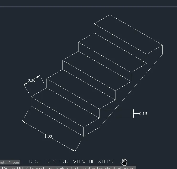
- For the Plotting the isometric view the drafting mode is changed to isoometric mode by using the option in the status bar in the bottom of the window.
- In the isometric mode the polar tracking angle is changed with respect to the plotting.
- The steps are plotted by using the poly line command or by using line command.
- The simple process it is better to draw a single step and the rest of the steps are copied with reference to the first step with the base point with zero displacement.
- The step is plotted by using poly line command and care should be taken the isometric angle should be sane on both sides of the step.
- By using the polar trcking the angle of deviation of step is plotted carefully.
- By using the poly line command the step with a length of 1.0 and the tread width is 0.3 and rise thickness is 0.15 is plotted using the poly line command.
- By using the copy command the steps are copies in the upward direction to form the isometric view of the steps.
- Now using 'Dimlinear' command the dimensionsof the steps are measured.
- The properties of the dimensions can be changed using the 'Dimstyle' command and the properties of dimension line,line type,line weight,Text size and angle etc can be changed from the modify option.
- The result of the Isometric view of the steps is obtained as shown below.
C 6- Isometric view of the Gabble wall
- Click for the new drawing in the file menu and open new drawing and selet the template according to the units of the drawing either imperial or metric unit and please click on the advance set up and make sure all the setings regarding units,area,angle ,angle measure is all set and the ready the drawing sheet is ready to plot.
- After the advance set up in the drawing, Enter units(UN) command in the command bar and set the type of the units and its precision to the accuracy and click on OK.
- Before plotting it is better to check the dimension style(Dimstyle) command and click on modify and check the type of units in the primary units option.
- For the Plotting the isometric view the drafting mode is changed to isoometric mode by using the option in the status bar in the bottom of the window.
- In the isometric mode the polar tracking angle is changed with respect to the plotting.
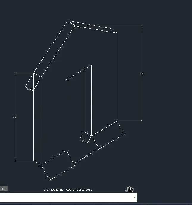
- The wall can be plotted with the poly line command.Using the polyline command the wall plotting is easy to enter the length of the walls in the command bar.
- The top ridge is formed either by poly line or by strecthing the lines using the 'GRIPS'.
- Now using 'Dimlinear' command the dimensions of the wall is measured.
- The properties of the dimensions can be changed using the 'Dimstyle' command and the properties of dimension line,line type,line weight,Text size and angle etc can be changed from the modify option.
- The result of the Isometric view iof gable wall is obtained as shown below.