Creating a Residence Layout, Seating plan, Toilet and Utility room plan using AutoCad
1. Aim: To create the lay out of a residence in the Auto cad using Engineering system.
Procedure :
- Click on new File and create the new template for potting the drawing
- Now enter units (un) command and select the engineering system in the units and also set the precision of the units and insertion scale to inches and click on ok.
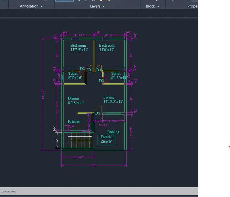
- Now the lay out plan is plotted using the various commands.The outer line of the building is plotted using the line or poly line or rectangle command to a size of 43'6.5" and 25'.
- Now enter offset distance of 9" for all the four sides which forms the external walls of the building.
- Now using the offf set command the bed room walls are plotted to an off set distance of 11'7.5" and 11'6" from the vertical external walls and with an offset distance of 12' from the horizontal external walls.
- Now using the trim command trim the corners edges which are merged and the boundary wall edges are formed.
- In this way using the offset command the walls of the different rooms are plotted with respect to the sizes of the rooms.
- The Stair case is also plotted using the offset command with an offset distance equal to the tread width of 1'.
- The line type of the upper flight of the stairs are modified as dotted line using the properties tool in the ribbon.
- The Doors and windows are plotted by using the 'BLOCK' command.The doors of size D1 3'X6'8",D2 2'6"X6'8", D3 3'3"X6'8" are converted in to the blocks and later they are inserted at the respective positions with required angle.
- The Details of the rooms are plotted with the text command. The text command will be single line text or multiline text.
- The text style is created or modified by using the 'ST' command. In the st command the text font,size,lineweight etc are modified and set as current to use the style in the lay out.
- The dimensions of the layout is plotted using the dim linear command. For the clear understanding the dimension style is also created in the dimension(D) command. In this command the linetype, arrow type, size,text of the dimension,jog factor etc are modified and set as current style.
- Now using the layers command assign layers to the different components of the building.
- New layers are created and specified colours are assigned to each layer and each individual components of the building.
- These layers help to lock or freeze the components of the building while plotting.
- The final layout of the residence is obtained as shown inthe below.
2. Aim: To create the lay out of a residence in the Auto cad using Engineering system.
Procedure :
- Click on new File and create the new template for potting the drawing
- Now enter units (un) command and select the decimal system in the units and also set the precision of the units and insertion scale to millimeters and click on ok.
- The seating plan is a round table so we can plot the seating plan by using the circle command.
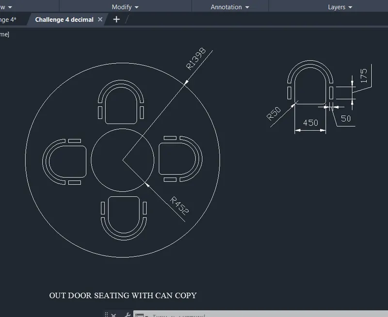
- Enter the circle command in the command bar and specify the centre ponit and enter the radius as 1398 and plot the circle.
- Now enter the circle command with the same centre point and enter the radius 452 plot the circle.
- Now draw the plan of a seating chair separately on the sheet with the specific dimensions.
- The seating arrangement is made with the help of a array command.In the array command select the polar array which is helpful to arrange the seating plan ina circular manner.
- The seating arrangement is also plotted by converting into the block and inserting into the respective position with the specified angle.
- Create the dimension style if required and using the dimlinear command plot the dimension of the seating arrangement.
- The final seating arrangement is obtained as shown inthe below.
3. Aim: To create the plan of toilet and utilities room in the Auto cad using Engineering system.
Procedure :
- Click on new File and create the new template for potting the drawing
- Now enter units (un) command and select the decimal system in the units and also set the precision of the units and insertion scale to millimeters and click on ok.
- The walls of the toilet and utilities room are plotted by using the lin command or poly line command.
- Here the wall thickness is different, so if we use poly line command then it should be exploded to avoid the interruption during the usage of the offset command.
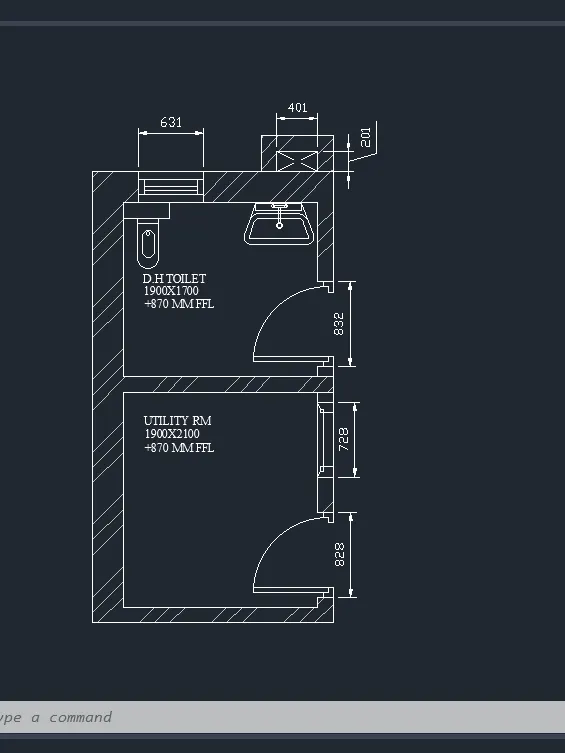
- The off set command is used to plot the wall thickness to an off set thickness of 300mm on main walls and 150 mm thickness onthe partion wall.
- Doors are created using the block command and later they are inserted in to the respective position.
- Hatching of the wall is created using the hatching 'H' command .The specified transperancy and scale is changed in the hatch edit bar.
- The water closet and wash basin may be plotted are they can be inserted from the reference from the Autocad design centre 'ADC' command.
- The Details of the rooms are plotted with the text command. The text command will be single line text or multiline text.
- The text style is created or modified by using the 'ST' command. In the st command the text font,size,lineweight etc are modified and set as current to use the style in the plan.
- Create the dimension style if required and using the dimlinear command plot the dimension of the Toilet and utility room.
- The final plan of the toilet and utility room is obtained as shown inthe below.