Door Arm Rest Week 8 Challenge
AIM : Creation of Door Arm rest and add thickness to it.
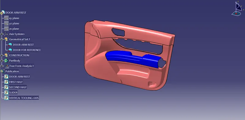
Detailed report :
Method Followed :
- Creating tool axis and slide core axis(Slider) .
- Creating Class B surface from given Class A surface.
- Creating Class C surface from Class A & B surface .
- Creating a solid body by using a closed surface.
- Performing a draft analysis.
1. Creating tool axis and slide core axis(Slider) :
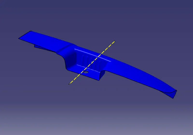
- To create the tooling axis, we need the proper orientation or view that gives the correct features and draft available in the component.
- So here the component view from the Z direction gives the proper view for the tool to see the features present in the geometry.
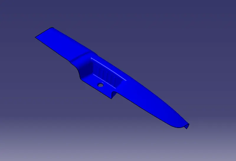
Tooling axis created by following steps :
Extracted the circle surface.
Center point is created by using the on surface at zero.
Make a vertical line from that point and we get a vertical tooling axis.
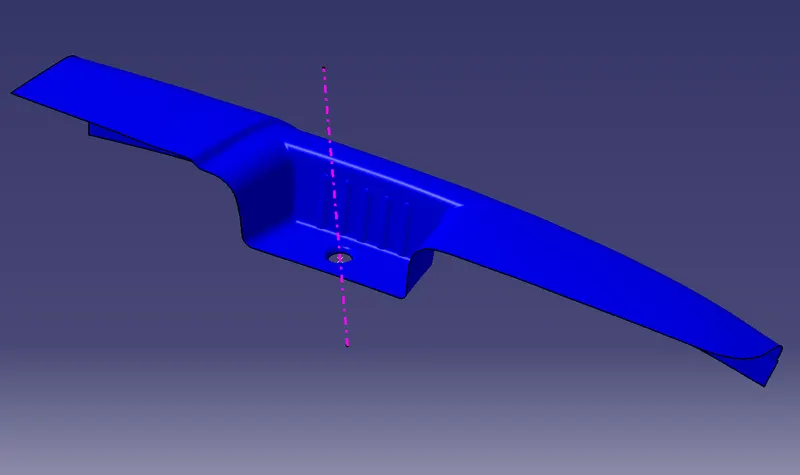
Slider :
Extract the side surface of Class A by visualising.
Make a point on the surface and make a line perpendicular to the surface then name it as the slider axis.
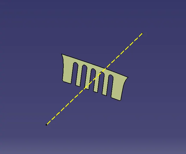
2. Creating Class B surface from given Class A surface :
We extracted a Class A surface and worked on it separately to create Class B surface
- Base
- Walls
- Door Arm rest surface
1. Base :
- Extract the surface
- Untrim the surface
- Extrapolate it
- Offset it by 2.5mm to the downward.
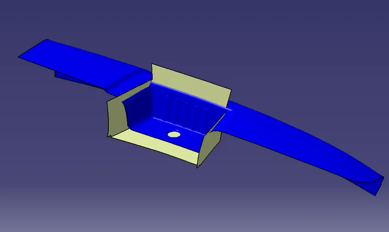
2. Walls :
- Extract the three walls separately
- Un-trim the surface of three extracts
- Extrapolate them
- Trim them with each other.
- Offset the given surface by 2.5mm to the downward direction.
3. Door arm rest surface :
- Extract it
- Un-trim the surface
- Extrapolate it
- Offsetted by 2.5mm to the downwards.
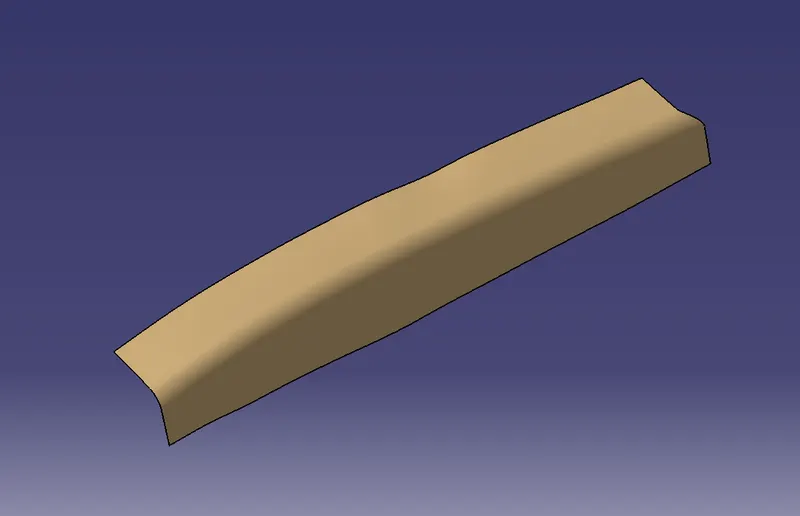
first half :
second half :
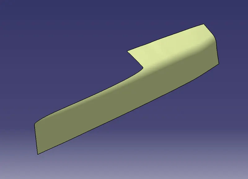
To get the curved surface we followed following steps :
- Make an axis system and create a positioned sketch.
- Take an intersection of Class A by intersect 3D element command.
- Make a line and adjust it as per intersection and constraint it.
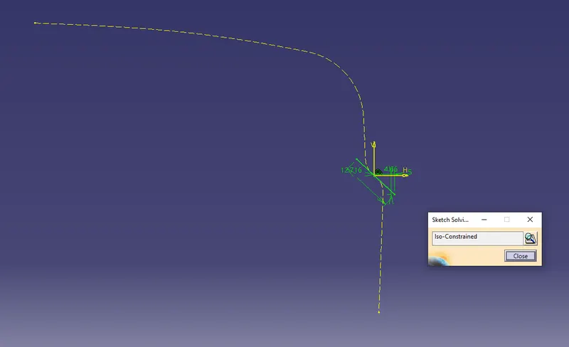
- After that, extract the line which is bisecting the axis system.
- Curve smooth that line and sweep the sketched line along this guide curve.
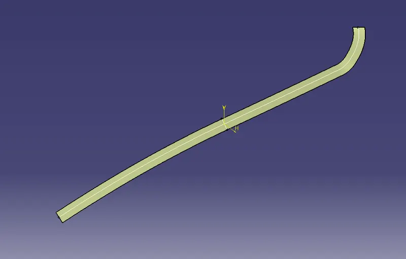
trim first half, second half and curved portion together :
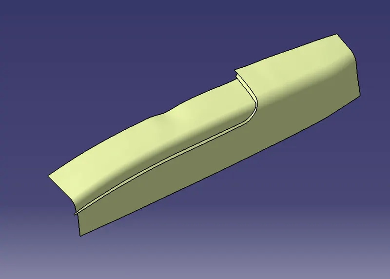
Trim the Walls, Base and arm rest surface to get Class B and give edge fillets by calculating fillet value. The Class B surface is given in the below image.
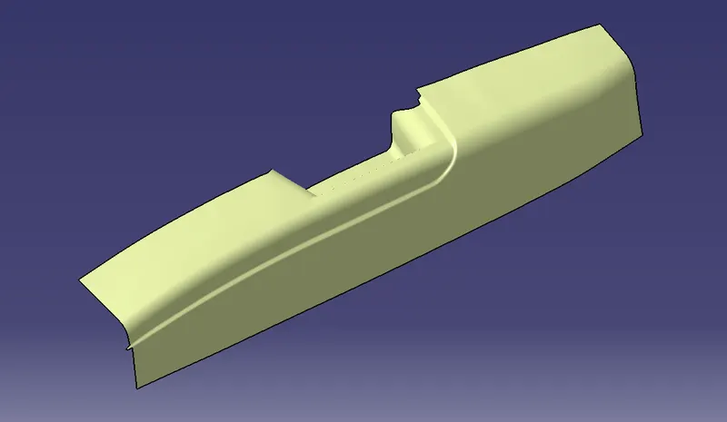
3. Creating Class C surface from Class A & B surface :
Extract the boundaries of the Class A surface by using multiple extracts and make them into smooth curves.
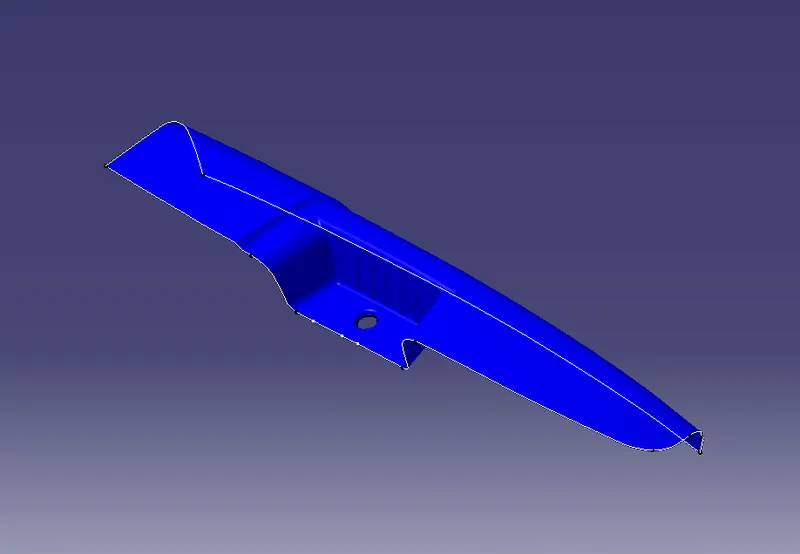
Use Multi-sections surface where the sweeping is not working due to the curve.
Sweep the boundaries with the help of tooling axis and give 3 degree draft in outward direction.
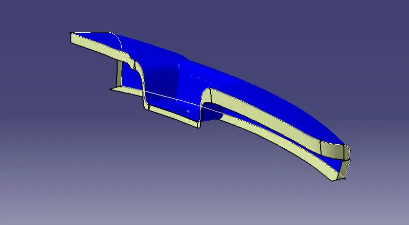
Extrapolate it by 3mm to trim it to join.
Final join :
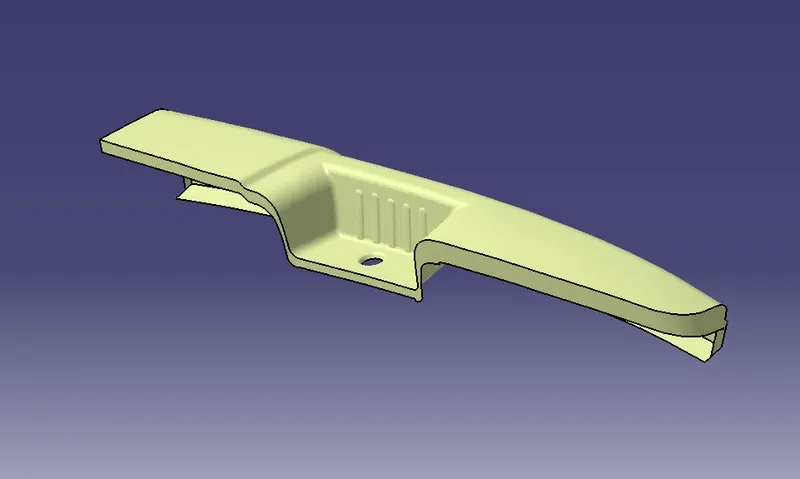
First of all join the Class A and Class C surface together.
Then trim them with a Class B surface.
Check the surface whether it has a boundary or closed. After trimming we get the final Door Arm Rest surface.
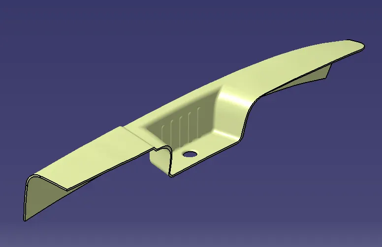
4. Creating a solid body by using a closed surface :
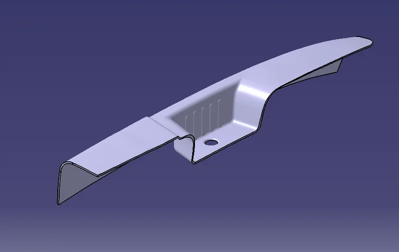
Solid body is created by a closed surface feature in the Part Design workbench in the defined partbody. This is our design output shown as given below,
5. Performing a draft analysis :
To perform draft analysis, Go to the insert > Analysis > Feature draft analysis.
Switch customize view parameters and select material.
Click on the compass icon and align it with the tooling axis & click on the surface, we will get our results.
From the below image we can see that the surface in green colour has a more than 3° draft which is most required for tooling feasibility. Also see the color variant display box.
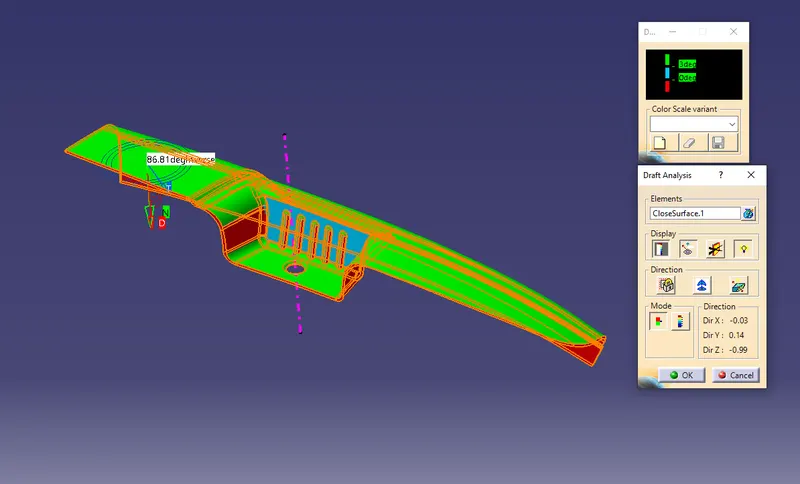
Image of the model with the proper colour code of the draft angle ,
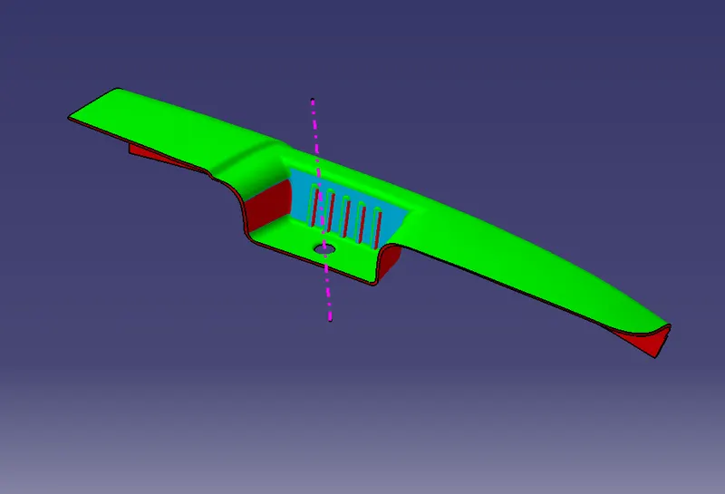
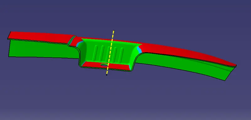
On Slider tooling axis :
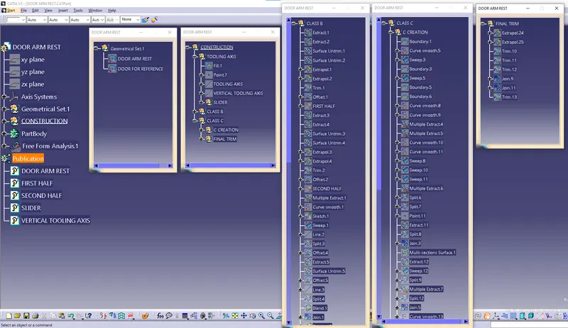
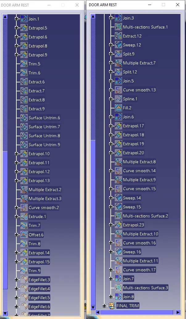
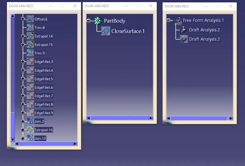
Images of the expanded Tree structure of the Geometrical set, part body and publications.
Conclusion : Created the Door Arm Rest Plastic component through the given Class-A surface and performed Draft analysis.