Door Arm Rest Week 8 Challenge
Aim:
To create a solid for the given model and perform Draft Analysis.
Instructions:
The below steps represent the phases in which the door arm rest console was designed
1. Bringing the aesthetic Class A surface of the Door arm rest.
2. Determining main tooling axis for the Door arm rest.
3. Determining slider tooling axis for the undercut.
4. Performing Draft analysis for both the tooling axis.
5. Designing of Class B surface.
6. Designing of Class C surface.
Procedure:
Open the Generative Shape Design from the Start Menu in software.
Select the open option from the File menu.
Select the model and click on Open.
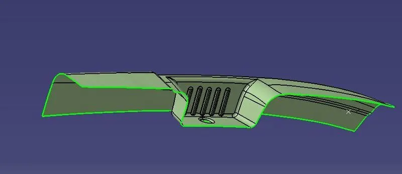
Tooling Axis:
Intersect the model with the plane perpendicular or to an axis system.
Extend the lines which are perpendicular to the plane.
Again intersect the model with another plane and extend the lines perpendicular to it.
Create a bisecting line by bisecting option in Line definition.
Rename it as Tooling Axis.
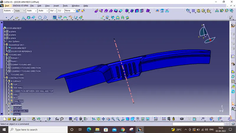
Class B surface:
First half:
- Extract the surfaces with no propagation in extract option.
- Untrim them.
- Extrapolate the surfaces with point continuity of distance 20mm.
- Trim the surfaces to get the required shape.
- Offset those trimmed surfaces with thickness value.
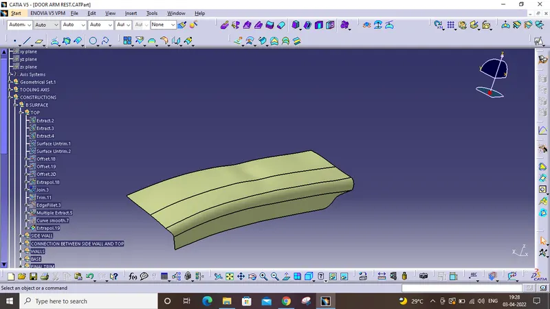
Second half:
- Repeat the First half steps with different surfaces.
- Create a point on connecting surfaces between first and second halves.
- Insert the axis system and that point as origin.
- Intersect the surfaces with the plane.
- Create a tangency line with the curved surfaces.
- Extract the lines by multiple extract options with tangent propagation.
- Select the with reference surface option in Sweep option.
- Select the tangency line as profile and extracted lines as guiding curves.
- Extract the surface in the connecting region, Untrim it.
- Create a line with some angle on connecting surfaces and split it with surfaces.
- Use multi sections surfaces to create a surface.
- Extrapolate the surfaces if they are not crossing each other.
- Trim the surfaces accordingly.
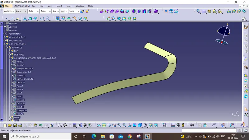
Side walls:
- Extract the side walls with no propagation in extract option.
- Untrim them.
- Extrapolate the walls with point continuity of distance 20mm.
- Trim the walls to get the required shape.
- Offset those trimmed walls with thickness value.
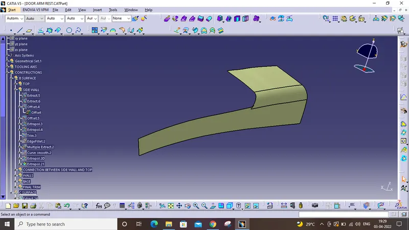
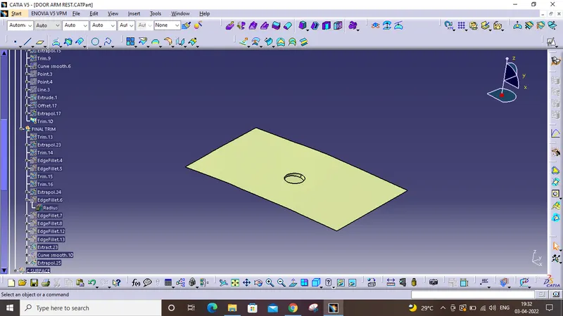
Base:
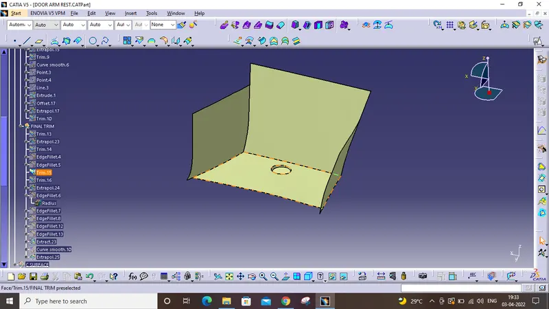
- Extract the base surface and untrim it.
- Extrapolate the surface.
- Offset the surface with thickness value.
- Repeat the steps for the circular part.
- Trim all the surfaces.
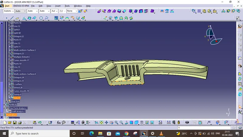
Class C Surface:
- Extract the boundary line of the half part of the model. .
- Smooth the curve and Sweep it with the reference surface option.
- Trim the surfaces.
- Use Blend or Multi Sectional Surfaces for complex surface areas.
Final Model:
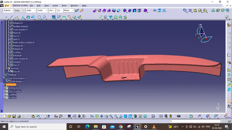
- Join Class A & C Surfaces.
- Trim the joined surface with Class B surface.
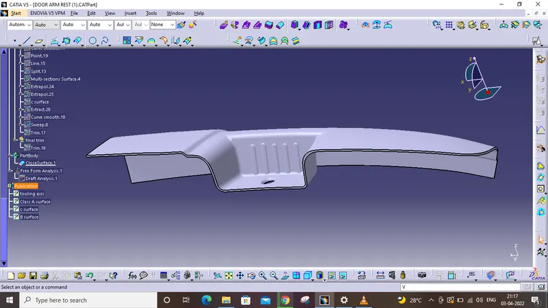
- Go to Part Design and insert a Body.
- Create a closed surface.
Draft Analysis:
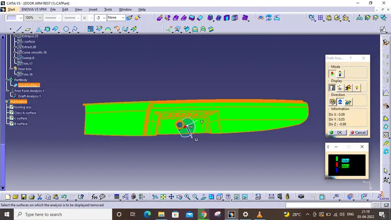
- Go to the Insert menu and select the Analysis option.
- Select Feature Draft Analysis.
- Select the Material option and select the surface.
- Drag the compass and place it on the tooling axis.
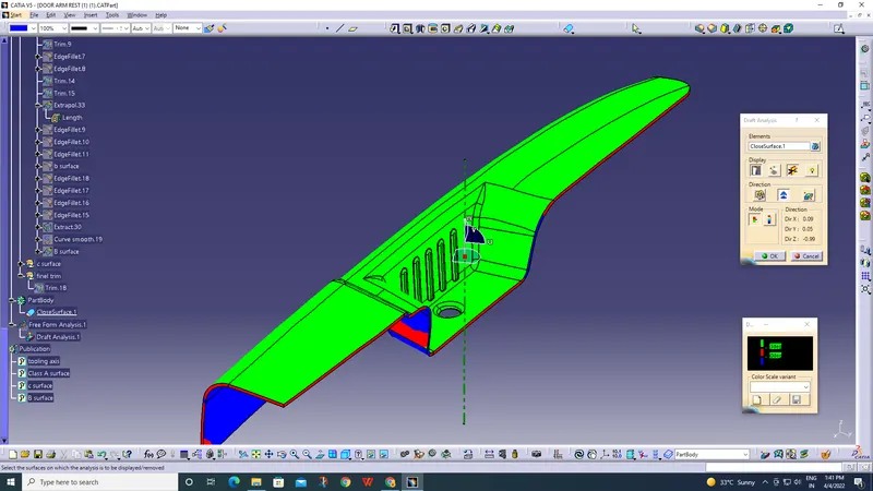
- Make sure that the top surface is in green colour as draft angle should not exceed 3deg.
- Click on Okay after confirming the model.
RESULTS:
A solid is created from the given drawings and performed the Draft Analysis.