Door Arm Rest Week 8 Challenge
Door Arm Rest- Week-8 Challenge
Objective:
To complete the Door arm rest component (Closed Body) from the provided A surface and to run Draft Analysis on it.
Process:
- Creation of two Tooling axes
- Draft Analysis on the Class A Surface
- Creation of B surface
- Creation of C surface
- Closed Body created using surfaces
- Draft Analysis on the Body
Creation of tooling axes
- The surfaces on the given model were checked for continuity and no gaps or discontinuity were found.
- The given model was analysed visually and Z-direction seemed to be the best direction for the tooling axis since both X and Y directions would require side cores or weren't feasible for the maximum draft angle requirement of 3 degrees for plastic components.
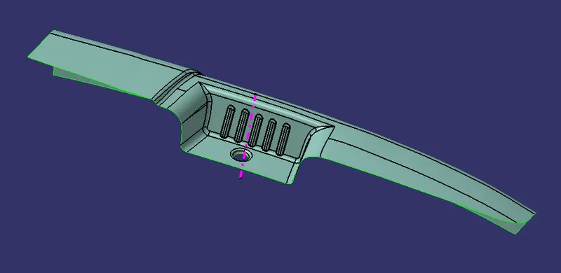
- The Tooling Axis was created using the Bisection method. A rough parting line was initially created along the Z direction using the centre point to be a visual aid.
- The curves were visually checked with the reference tooling axis. The lines which appeared to be parallel to the reference axis were used to create the bisecting line. The bisecting line which is created between two angular lines is the resultant tooling axis for that particular direction.
- The Line bisecting the tooling axes along both X and Y direction is the final Tooling Axis.
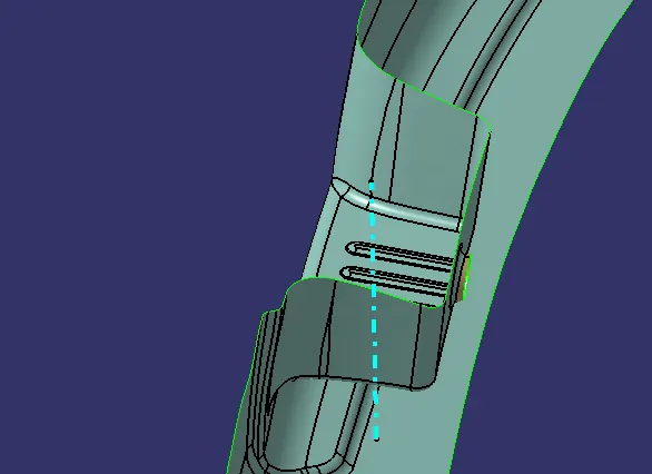
- The above process was repeated for the tooling axis along Y-direction.
- The Tooling axis on the Y-direction is provided for the Side Core.
- Both the model and the tooling axis were published for ease of access.
Draft Analysis
- The material mode was first selected in the view customization parameters. This setting is required for the Draft Analysis tool.
- The compass was used to create the draft direction for the component.
- The elements to be analysed were chosen and the Colour Scale displays the range of draft angles within the component. The standard maximum allowed draft angle of 3 degrees for plastic components was entered in.
- The given model passed for draft analysis.The running point option was used to check specific surfaces within the component which may seem parallel or almost parallel to the tooling axis.
- Draft Analysis was performed on the surface as well as the closed body on both tooling axes to ensure that the side core passes the Draft Analysis too
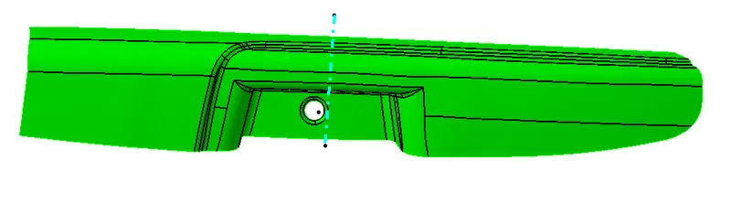
Draft Analysis along Z direction
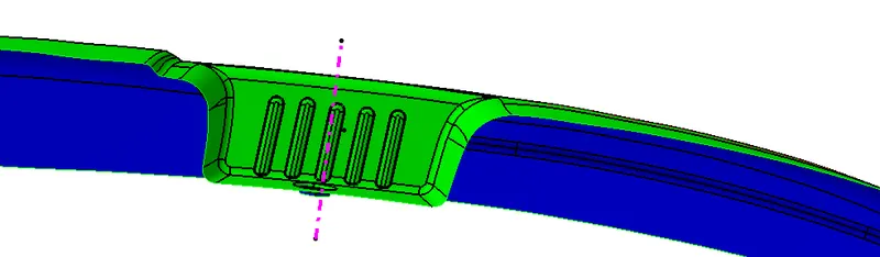
Draft Analysis along Y direction (SIDE CORE)
Creation of B and C surfaces
To create the B surface for the given Class A surface, the surfaces were extracted, untrimmed, extrapolated, trimmed into the required surfaces, split wherever required and the surfaces were offset to a distance of 2.5mm to accomodate the thickness of the component.
The respective fillet values were entered using the edge fillet option. The final output for the B surface was published for ease of access.
To create the C surface, the boundaries were extracted in portions, Sweep surfaces were made across either using the "with Draft direction" or "with reference Surface" options.
The Class C and B surface were trimmed together into one cohesive surface.
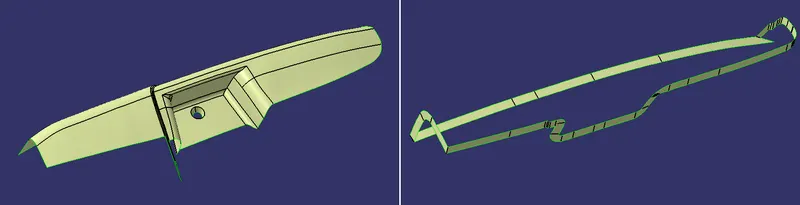
Creation of Closed Body:
The Class A,B and C surfaces were joined or trimmed together to create one complete closed surface.
The Close Surface option within the Part Design Workbench was used to create a Solid body from the created surfaces.
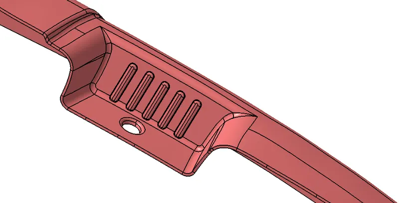
Solid body created using Close Surface option
Draft Analysis on the Solid Body:

Along Z direction tooling axis

Along Y direction Side Core tooling axis