Development of Door Trim Panel
AIM:
To Create the Development of a Door Trim panel using a CATIA V5 software with given Master Section
OBJECTIVES:
- Creation of CAD model considering following inputs as like in OEM and tier1 companies
- Class A surface
- Nominal Thickness: Refer Master Section
- Attachment Strategy:
- Find a attachment strategy for thr door panel complete work
- use Push pin with Dog house for Lower substrate - Door panel attachment
- use heat stakes for part to part attachment
OUTPUT REQUIRED:
- Create thickened part using master section for reference
- Create the mounting features as per design guidelines in the industry and with master sections
- Apply Material details:
- Draft analysis & Tooling analysis
- Creation of parting lines and check tooling feasibility
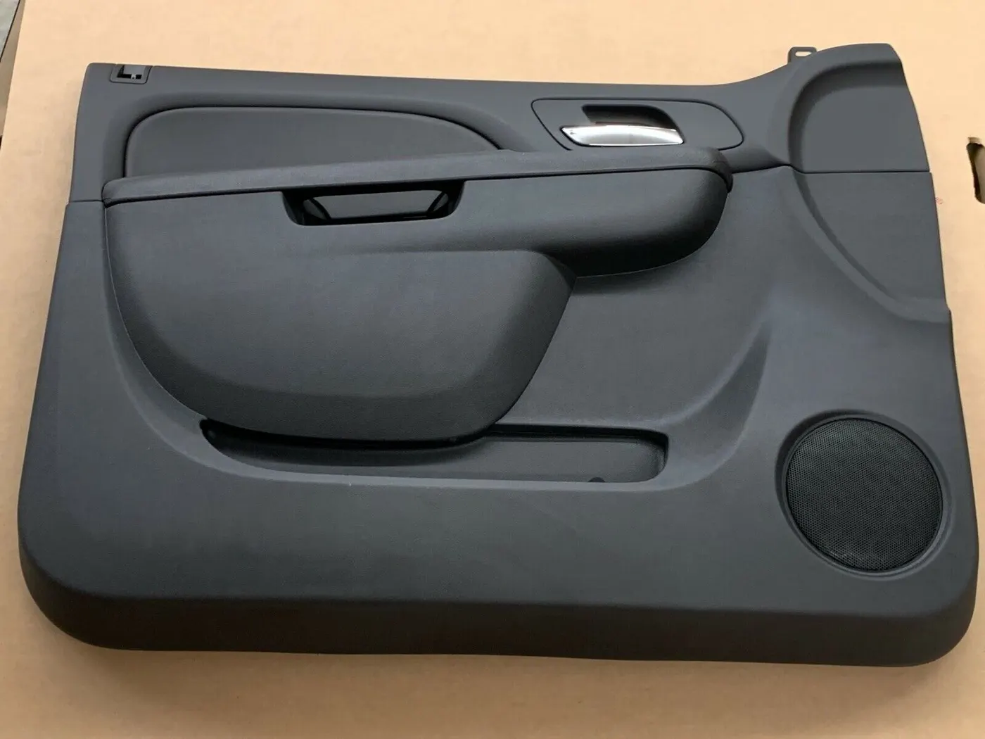
INTRODUCTION:
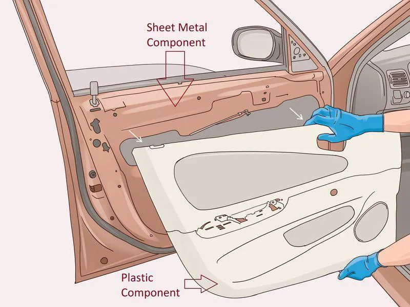
Door panels act as a barrier between the occupants of the vehicle and the door as well as between the inside of the automobile and the door's internal mechanisms. They must adhere to a number of design requirements pertaining to functionality, safety, and aesthetics. They should also maintain the dashboard's and the pillars' material motif while hiding the complex mechanical and electrical parts that control windows, locks, and other functions. The door panel has changed throughout time, going from a basic two-part lock and winding mechanism to a more intricate enclosure. Currently, doors have an inside full-width panel with speakers, a central locking mechanism, and electronic windows. Usually, a foamed core coated with fabrics or plastic makes up these panels.
DOOR TRIM PANEL CONSISTS OF FOLLOWING COMPONENTS:
- DOOR ARM REST
- UPPER MAP POCKET
- LOWER MAP POCKET
- LOWER SUBSTRATE
- UPPER SUBSTRATE
- FLANGES
- HEAT STAKES AND DOG HOUSE
Class A Surface:
- Surfaces in a product that are VISIBLE and here to the physical meaning are referred to as "Class A." The automotive industry is the primary application of this classification, with consumer goods following suit.
- surfacing of the "A" class and its significance: Surfaces of the A class are free-form aesthetic surfaces that are visible to us (interior and exterior) and have a high surface quality and optimal aesthetic shape.
- Class A surfaces have the following characteristics:
- visible surface with an appealing appearance;
- surfaces with textures;
- surfaces supplied by the customer (OEM);
- surfaces that lack features such as ribs, snaps, and so on.
- Class A surfaces are constructed from scanned data using various software, such as Allias.
- Class-A surfaces are those with curvature continuity.
Class B Surface:
At a specific thickness, the Class B Surface is located underneath the Class A Surface. Engineering Principles are used in its creation, and it has all the required components, including snaps, bosses, and ribs. From the outside, an observer cannot see this surface.
Class C Surface:
The surface formed to connect the Class A and Class B surfaces is known as the Class C Surface.
1. DOOR ARM REST:
It provides a convenient place to rest your arms while driving or riding in a vehicle. Small items like mobile phones, wallets, sunglasses, and chargers can all be kept in car armrests. Armrests for cars are a great way to make driving more comfortable and easier.
Procedure For Creating The Door Arm Rest:
- Class A Surface:
- In given Class A have some open boundaries
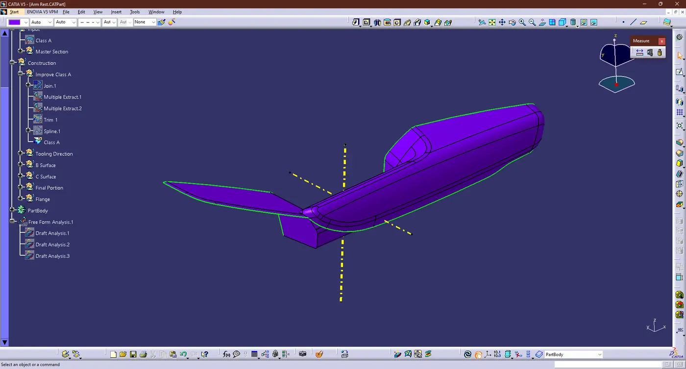
- First we need to clear the open boundaries, so i choose to join command remove the fillet
- Then Extract the surface with two portion then Trim the both portion and we got the new Class A Surface without open Boundaries
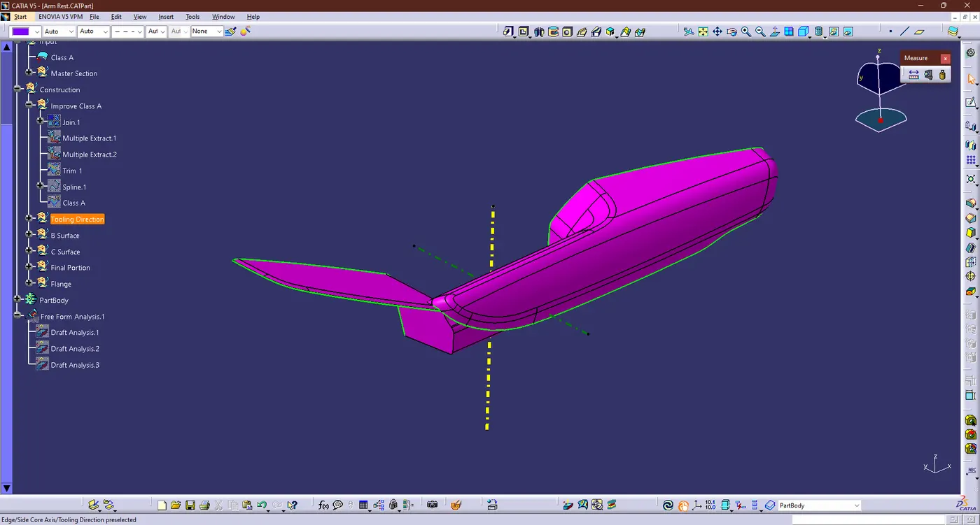
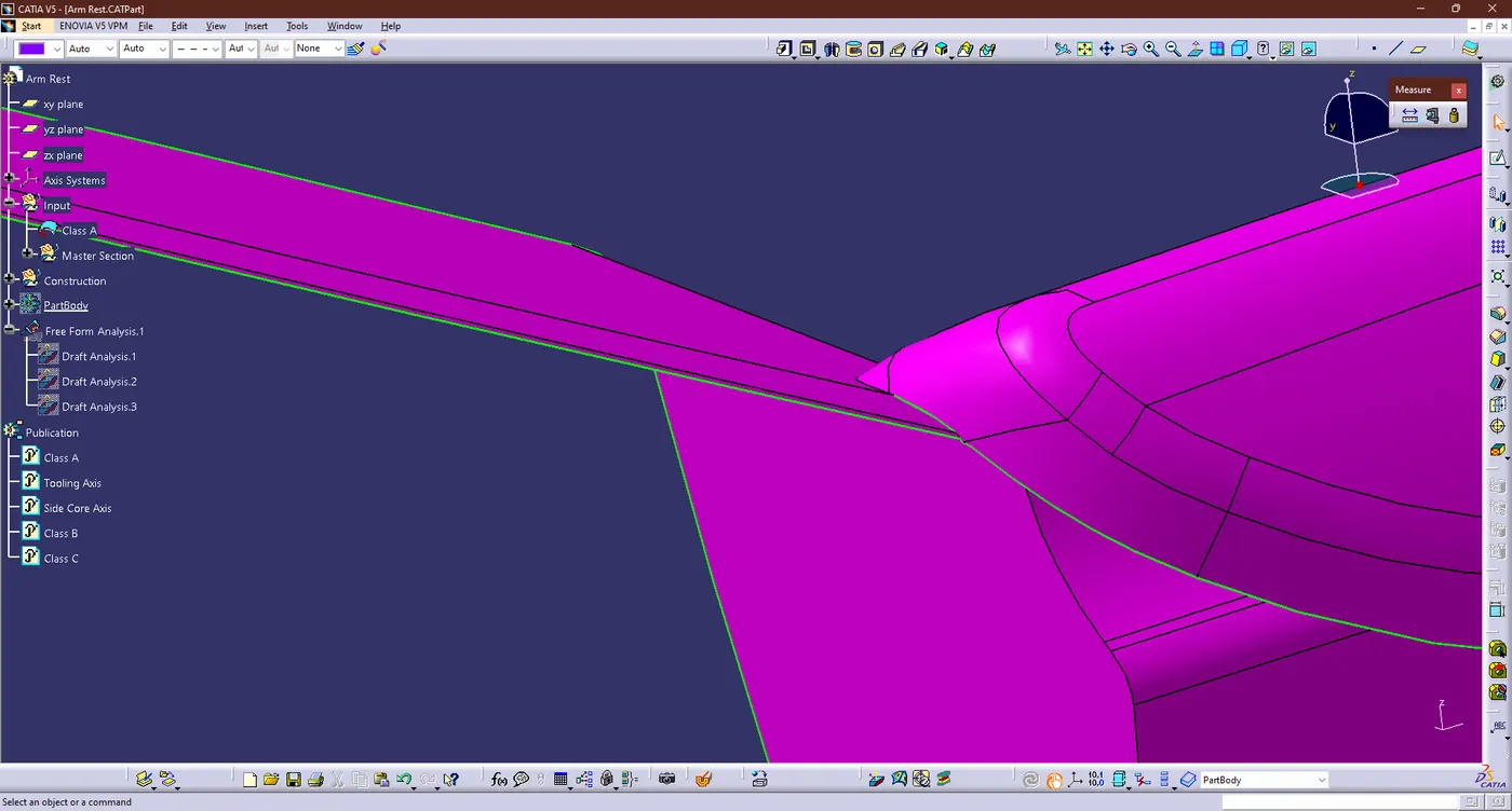
- Improved Class A Surface in Below:
- Creation of Tooling Axis:
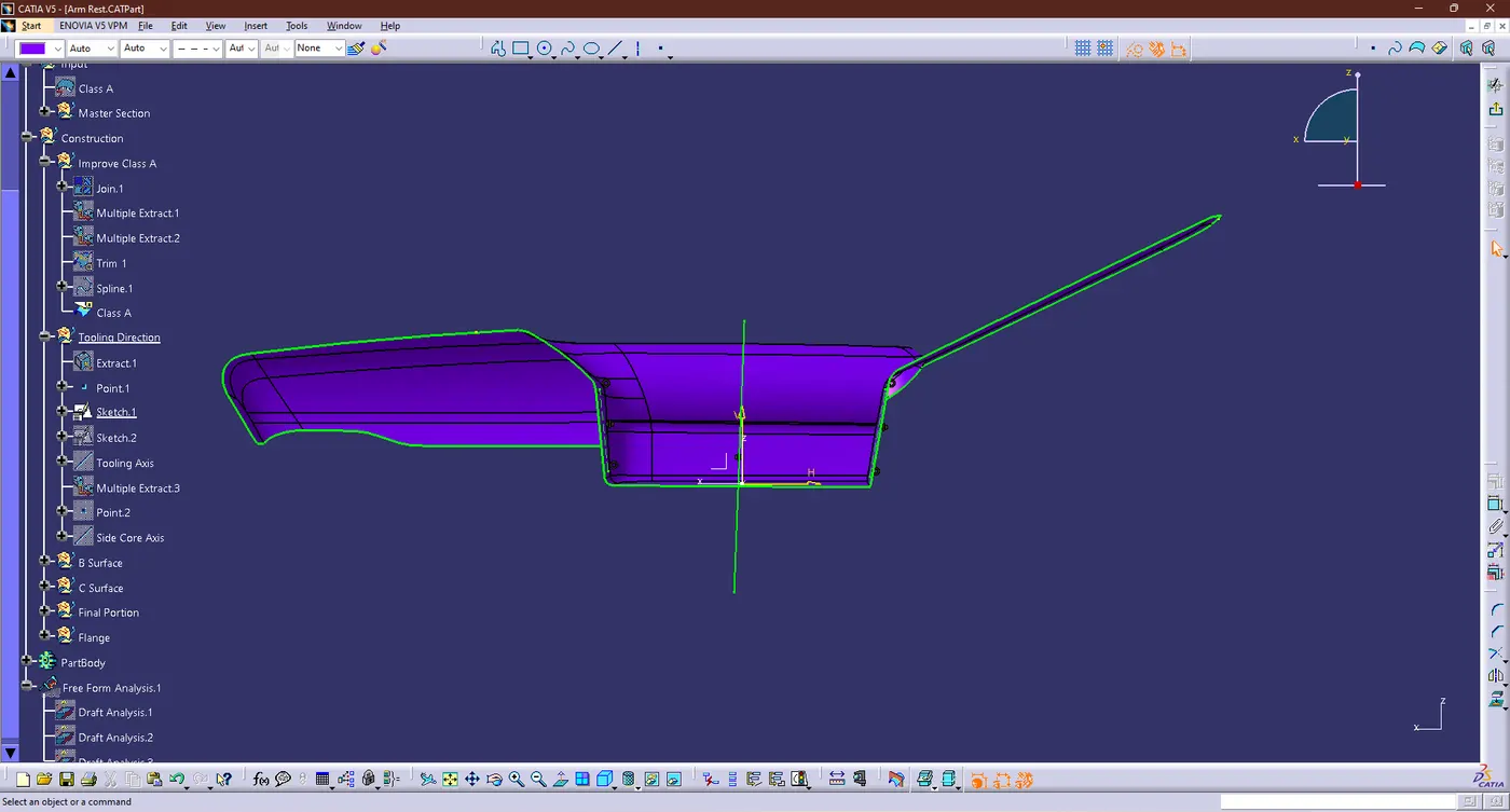
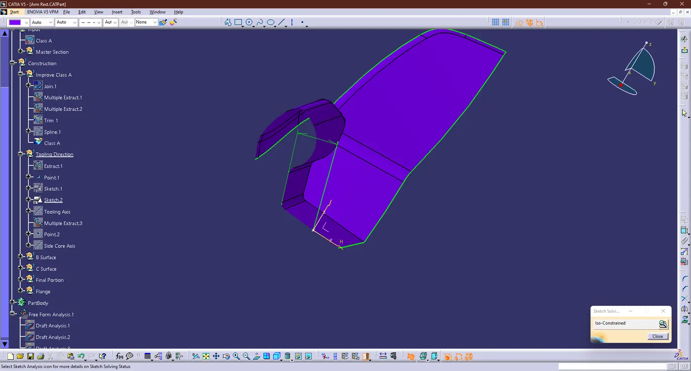
- The model is observed from 3 Planes and the xy plane is chosen for the details. So the Pocket base were chosen and a point has been created
- let the point taken has the reference and create a position sketch and then create the two line in the opposite direction
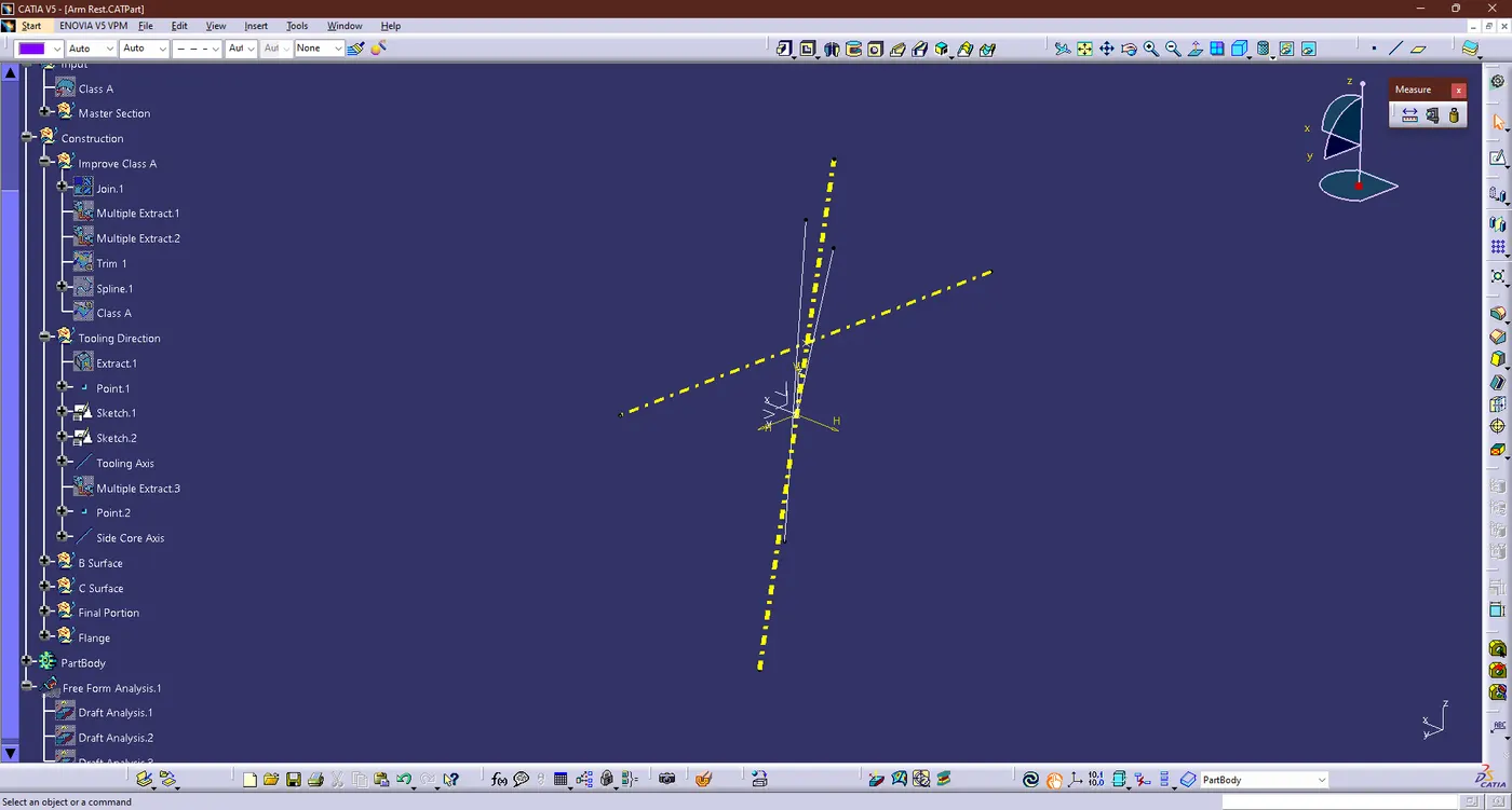
- Then create the another line by using the bisecting line option
- An then create another Position sketch other two side of the pocket same as well what should do in the previous sketch
- Now create the another line by using bisection line option and given name has "Tooling Axis" and then create another line using point-direction method in y axis and given name had "Side Core Axis"
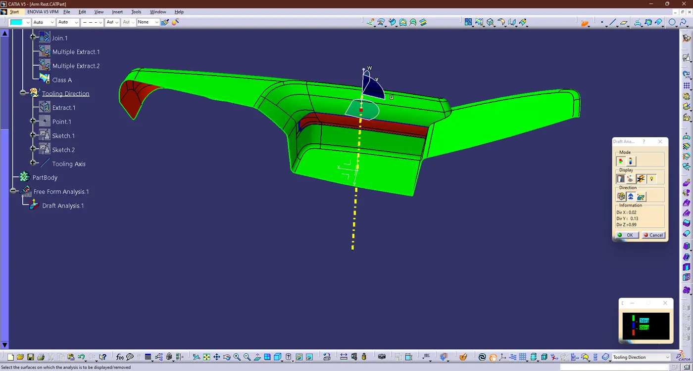
- Draft Analysis for Class A:
- We perform a draft analysis check for the Class A surface before we make solid part and creating features on Class B surfaces.
- Initially, I aligned the compass with the Tooling Axid and gave a Draft angle of 3 degrees for the green coluor on the Class A surface.
- Creation of B surface:
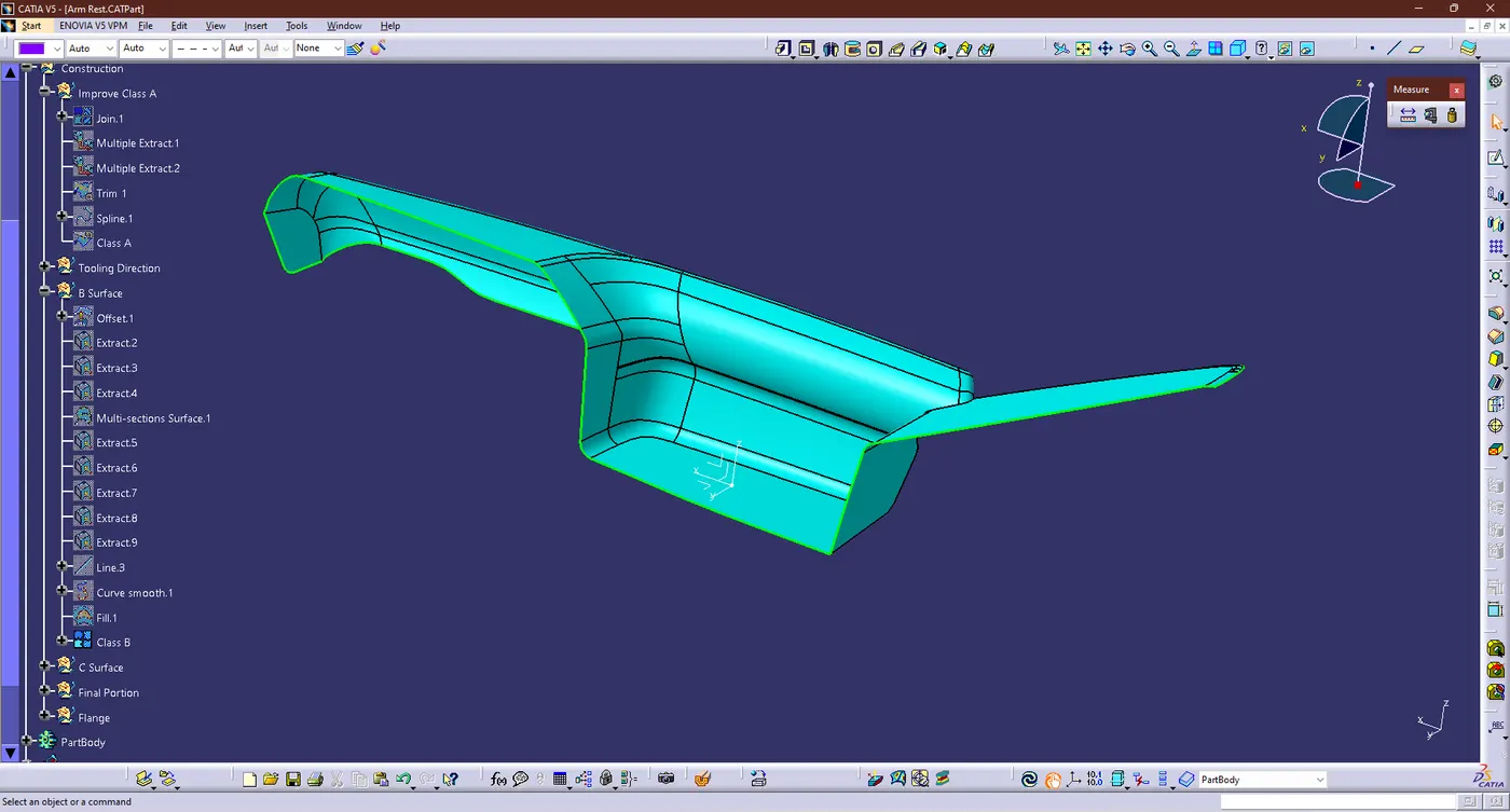
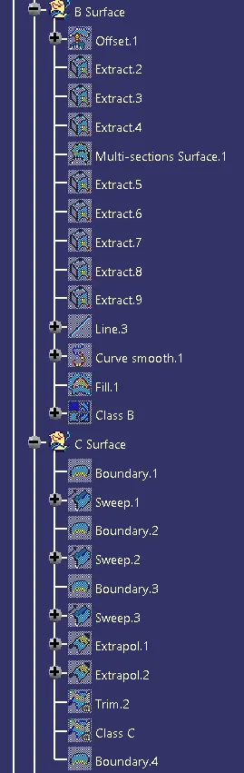
- A geometry set withh name B Surface was created, then the entire CLASS A surface was extracted separately.
- Then we do Offset the extracted Class A surface with 2.5mm and we got some open patches in offseted surface
- Now close the open patches by using those command like the Extract, Multi-Section Surface, Fill and join Command
- Now we got the B surface Arm Rest like wise mention below
- Creation of C Surface:
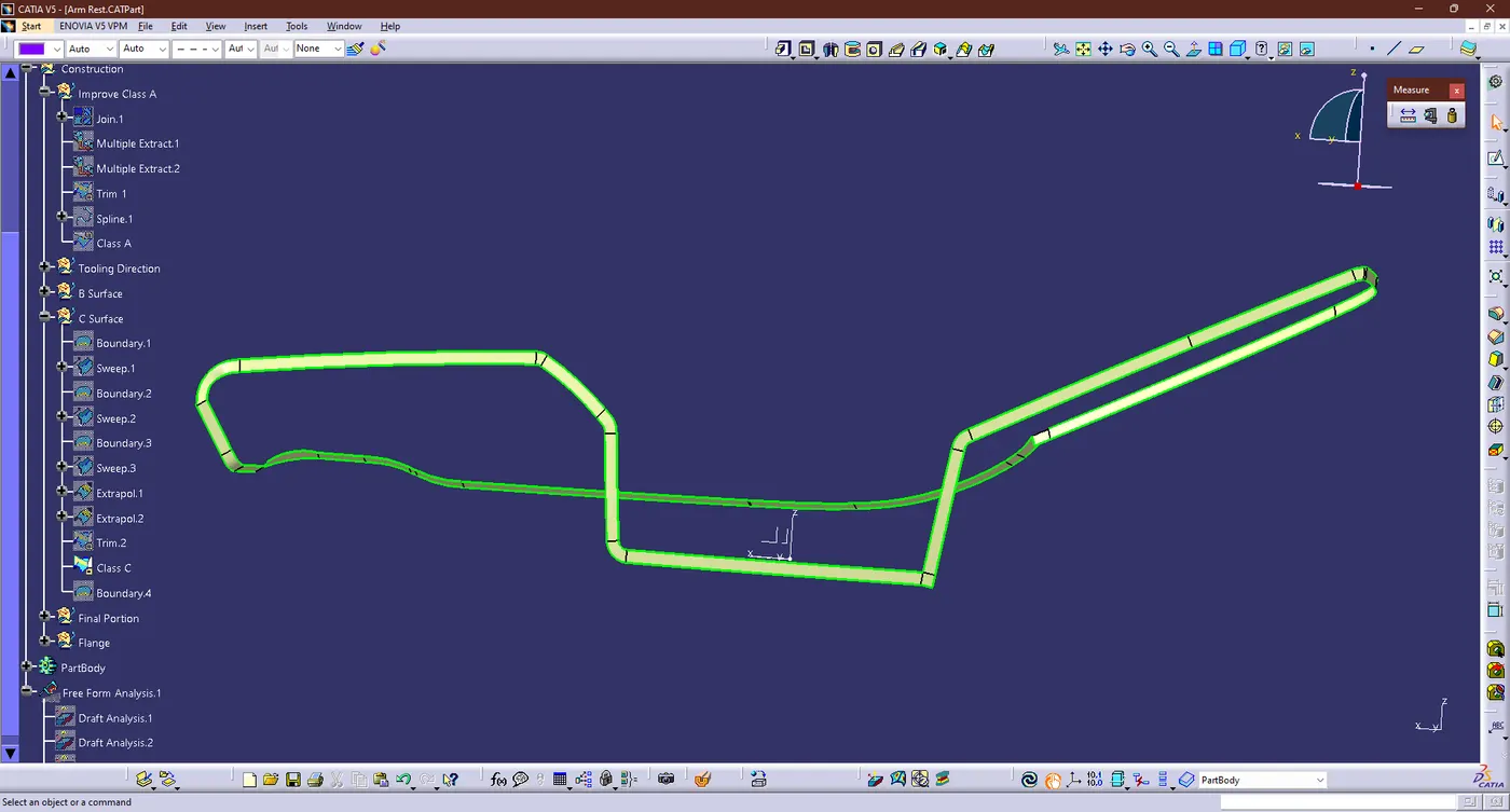
- First we need to create the boundary from the A surface for the C surface Creation.
- Then we do create a boundary part by part because of if we create the c surface in single bounday it lead some issue while we joining the A & C Surfaces.
- we will generate the Class C Surface by using the 'Sweep' command 'With Reference Surface' option to create
- Then we got the CLASS C SURFACE like this condition
- Creation of Final Portion:
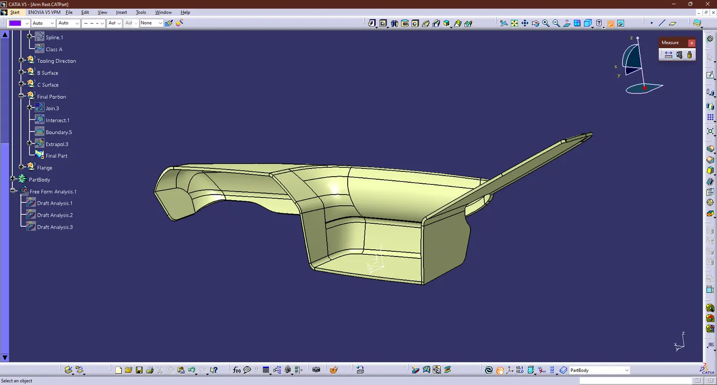
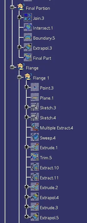
- First join the Class A & C Surfaces, using the join Command , Then trim with Class B Surface using the Trim Command
- Now we got the hollow part body of the "Arm Rest".
- Creation of Solid Body:
- The hollow were created as a solid by selecting the Body option and then selecting the Close body option and hence we got the final output were mention below
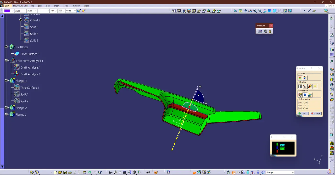
- Draft Analysis for SolidBody:
- In Plastic Design, the draft analysis or angle that is considered in the OEMs is 3 degree.
- Same thing were do follow for the draft analysis on earlier and output mention below
- Then we got degree has 2.5deg
- The draft is what enables the compenent to correctly release or eject from the mold. For parts to release correctly, all parts must have a draft in the direction of mold movement. Althought most parts or applications call for a minimum 0.5 to 1 deg, 3 deg is generally acknowledged as the standard.
- Draft analysis on the solid part resulted in green, blue regions.
- The green area shows the part that can be machined or manufactured by the casting machine
- The blue area indicated that the part may be OK for some OEMs but still needs improvements for other manufactures because the draft angle is greater than 3 degree
- A red color not appearing in this case indicates that the till angle is less than 3 degrees and cannot be manufacuted or if manufacturing will be defective.
- Creation of Flanges:
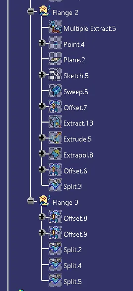
- Flanges are a notion that we acquire from mastersection. In order to account for the counterpart (lower substrate) location, I made flanges on the arm rest.
- There were two sketches made for the flanges. One is parallel to the base surface and the other is fastened to the body's C section. The intersection of a plane and the body's surface was where Sketch 1's bottom point fell. In this manner, we obtain a line with one end on the C surface's edge.
- Sketch 2 was created according to the master section, Then Sketch 1 was sweep along the edge of the C Surface and Sketch 2 was extruded along the line
- Then Trim both Extrude and Sweep and we got the Flange design
- Using planes, this trim was divided into the necessary flanges.
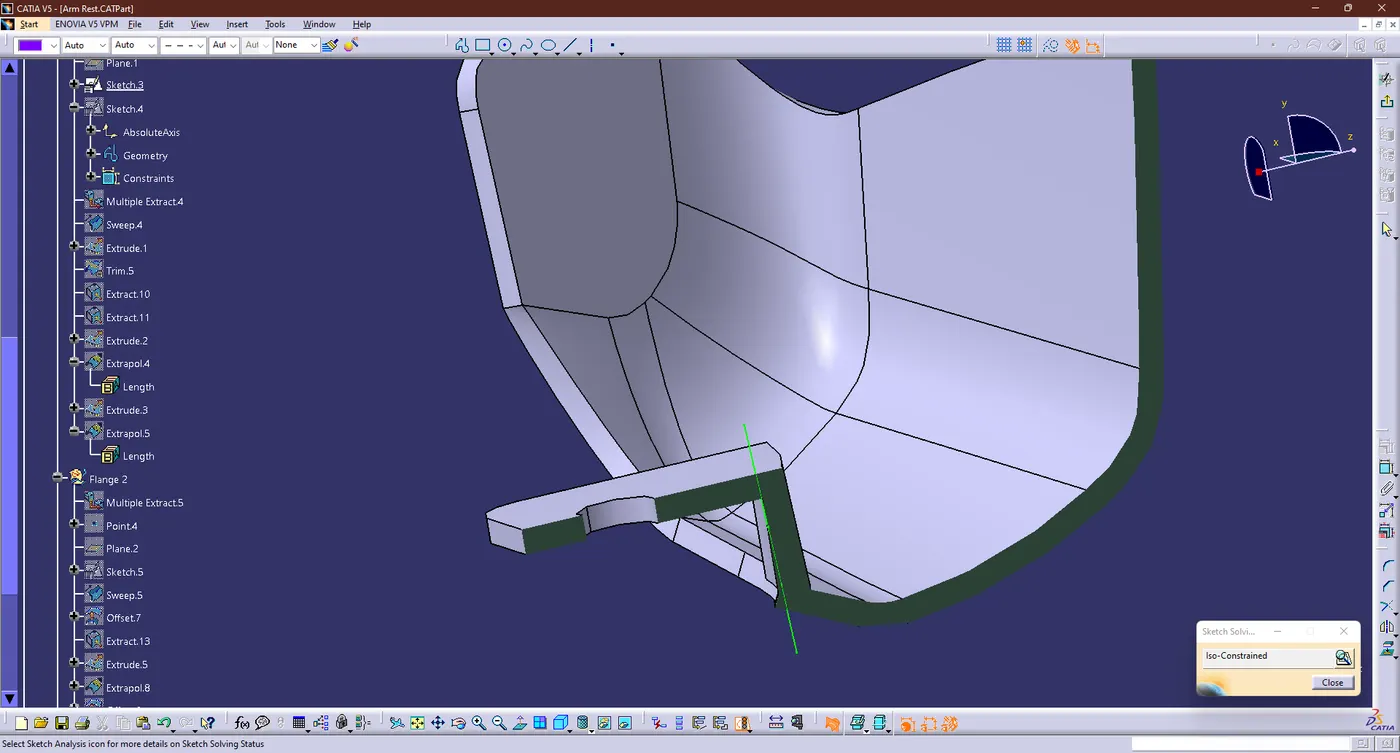
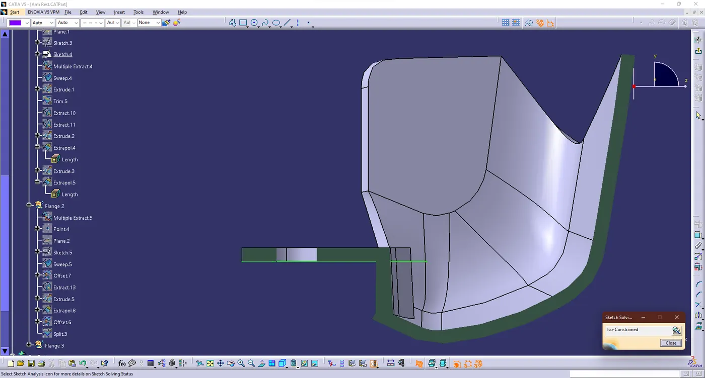
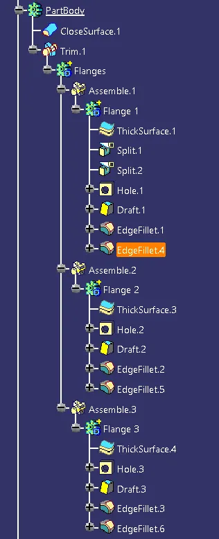
- These flanges were then thickned in the above direction to a depth of 2.5mm.
- The heat stake's surface is extracted,abd the offset is adjusrted to a specfic value, to create a hole in the flange.
- The angle of 0.5 deg was used to draft the hole face and the side walls.
- The front faceing verticals edges recived a 5mm fillet radius, while the remaining edges recevied a 0.5mm Fillet.
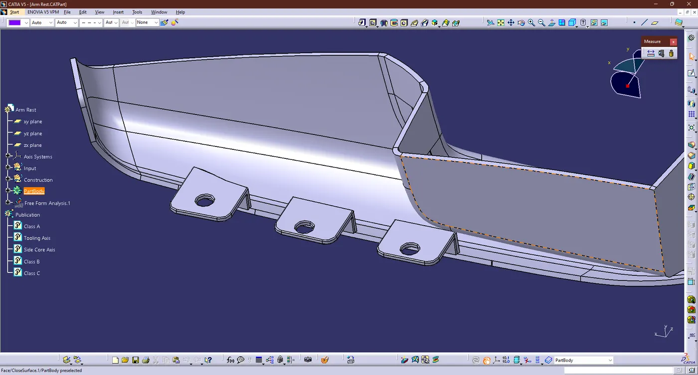
- Draft Analysis for Final PartBody:
- Same thing were do follow for the draft analysis on earlier and output mention below
- Then we got degree has 1.1deg
- We can see from the above draft analysis that the specified part is not as well-manufactured. A great deak of modification is required. We must ask the styling team to make specific improvement in Class A.
- Different Orientation of Arm Rest

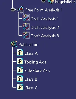
- Tree Structure:
2. MAP POCKET:
The map pocket, which is designed to extend beneath the door's armrest, is intended to hold small objects such as newspapers, periodicals, and atlases in addition to books.
Procedure For Creating Map Pocket:
- Class A:
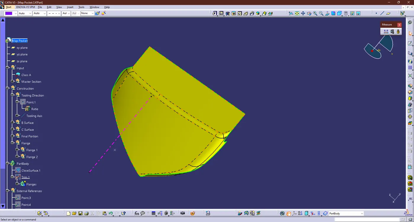
- Creation of Tooling Axis:
- The model is observed from 3 Planes and the zx plane is chosen for the details. So the curve side of Map Pocket were chosen and a point has been created
- let create a new line in Point-Direction option Then given direction has Y axis Click ok now we got the line
- Then line given name has "Tooling Axis"
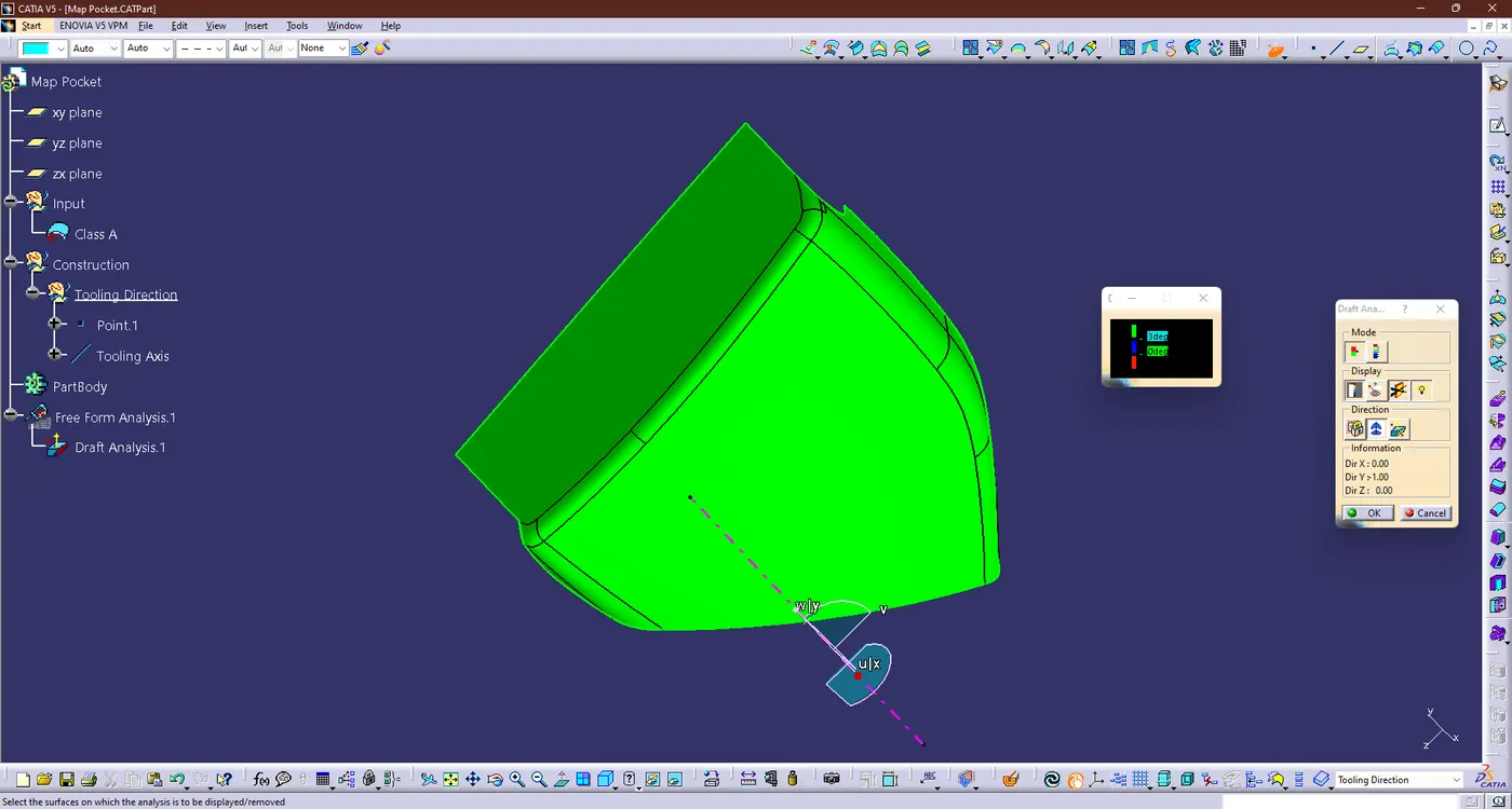
- Draft Analysis for Class A:
- We perform a draft analysis check for the Class A surface before we make solid part and creating features on Class B surfaces.
- Initially, I aligned the compass with the Tooling Axis and gave a Draft angle of 3 degrees for the green colour on the Class A surface.
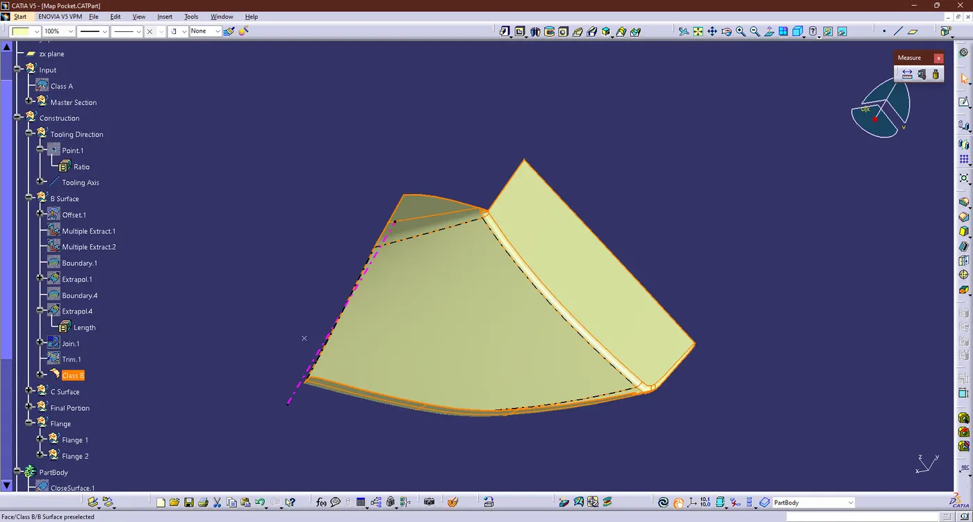
- Creation of B Surface:
- A geometry set with name B Surface was created, then the entire CLASS A surface was extracted separately.
- Then we do Offset the extracted Class A surface with 2.5mm as per Master Section
- Now we got the B surface Map Pocket like wise mention below
- Creation of C Surface:
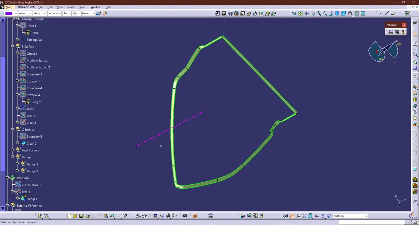
- First we need to create the boundary from the A surface for the C surface Creation.
- Now generate C Surface by using the 'Sweep' command 'With Reference Surface' option to create
- Then we got the CLASS C SURFACE like this condition
- Creation of Final Portion:
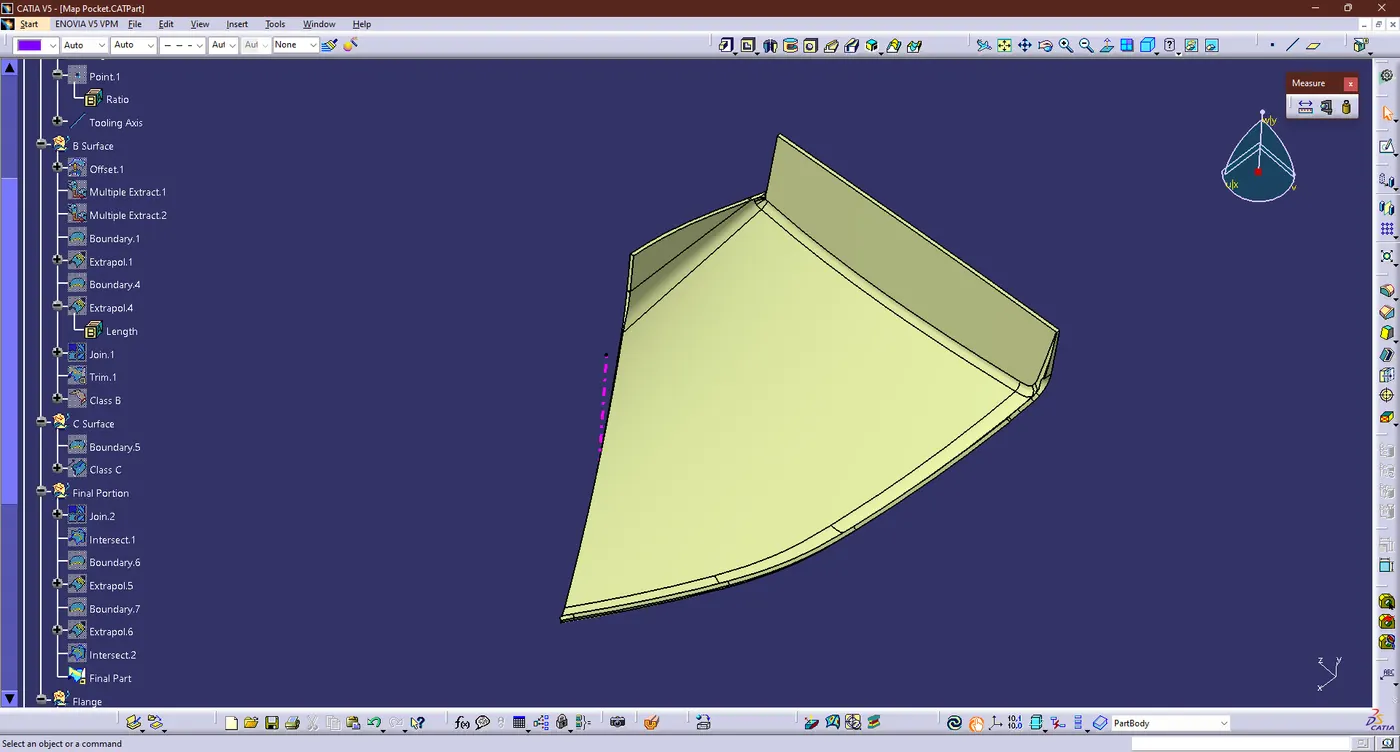
- First join the Class A & C Surfaces, using the join Command , Then trim with Class B Surface using the Trim Command
- Now we got the hollow part body of the "Map Pocket".
- Creation of Solid Body:
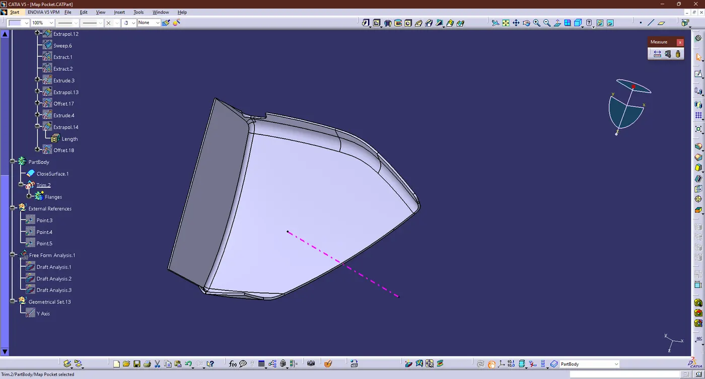
- The hollow were created as a solid by selecting the Body option and then selecting the Close body option and hence we got the final output were mention below
- Draft Analysis for SolidBody:
- In Plastic Design, the draft analysis or angle that is considered in the OEMs is 3 degree.
- Same thing were do follow for the draft analysis on earlier and output mention below
- Then we got degree has 1deg
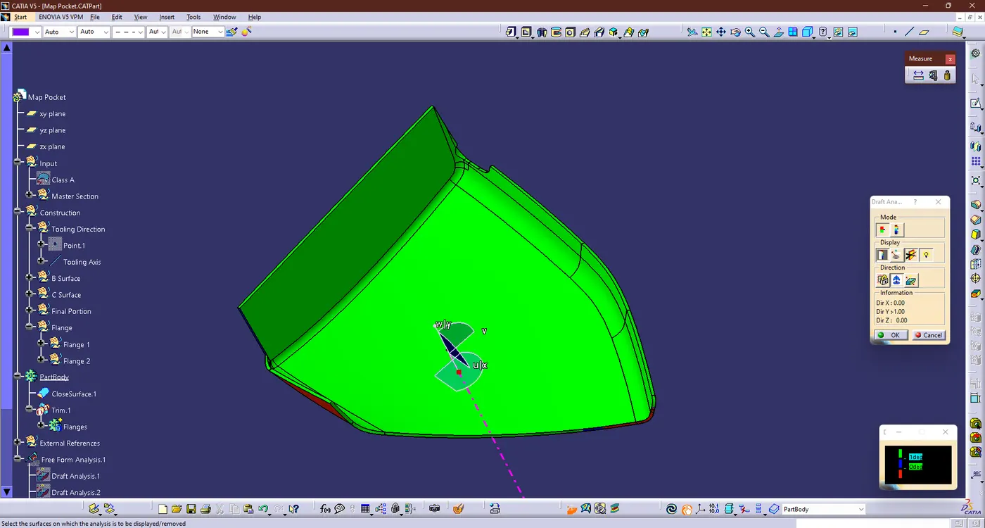
- The draft is what enables the compenent to correctly release or eject from the mold. For parts to release correctly, all parts must have a draft in the direction of mold movement. Althought most parts or applications call for a minimum 0.5 to 1 deg, 3 deg is generally acknowledged as the standard.
- Draft analysis on the solid part resulted in green, blue regions.
- The green area shows the part that can be machined or manufactured by the casting machine
- The blue area indicated that the part may be OK for some OEMs but still needs improvements for other manufactures because the draft angle is greater than 3 degree
- A red color not appearing in this case indicates that the till angle is less than 3 degrees and cannot be manufacuted or if manufacturing will be defective.
- Creation of Flanges:
- Flanges are a notion that we acquire from mastersection. In order to account for the counterpart (lower substrate) location, I made flanges on the Map Pocket.
- Where we need to create the point & Plan for creating sketch of flanges
- Then create a sketch using the Master Section and extruded then we got the Flange.
- Using planes, this trim was divided into the necessary flanges.
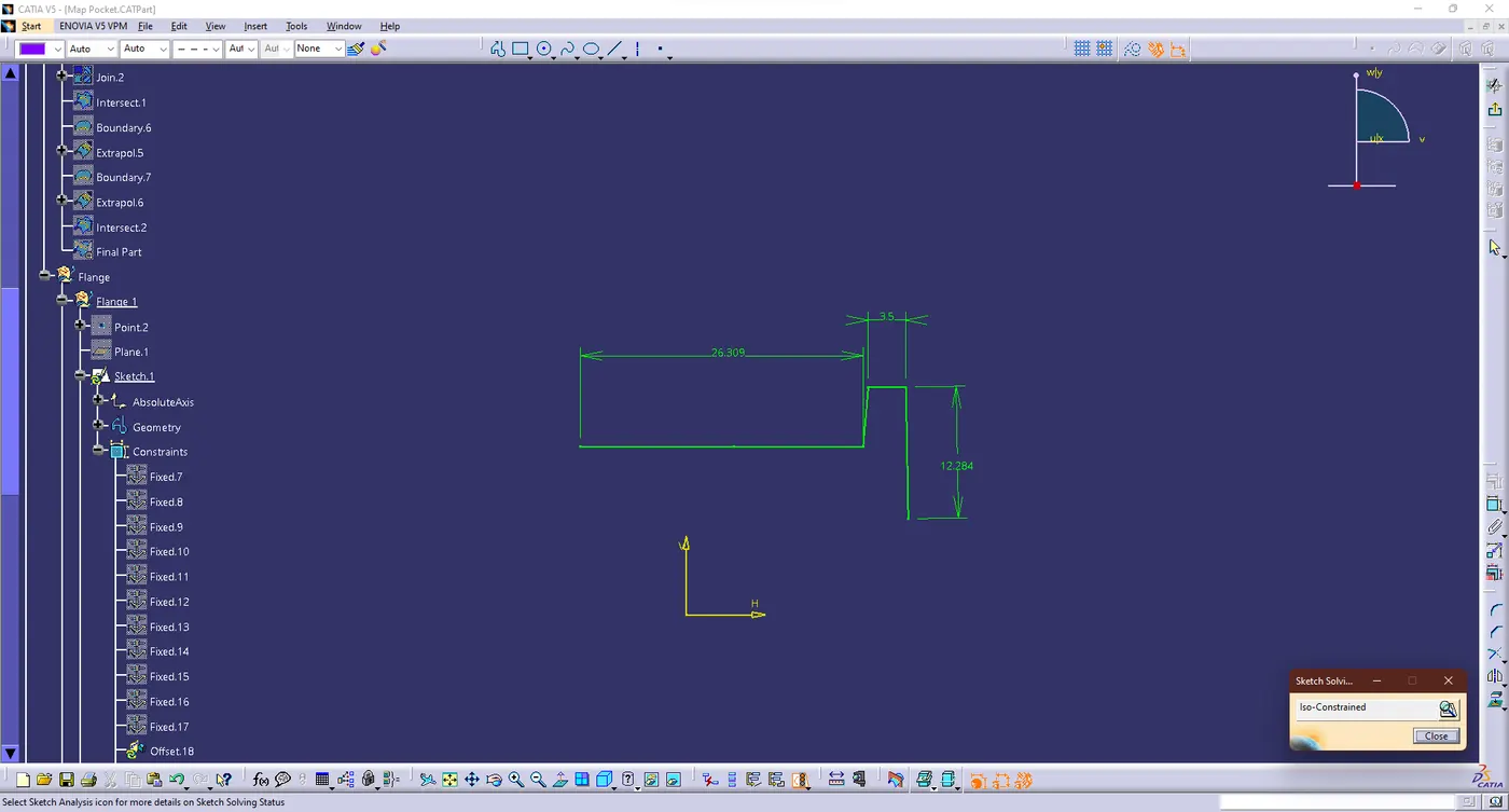
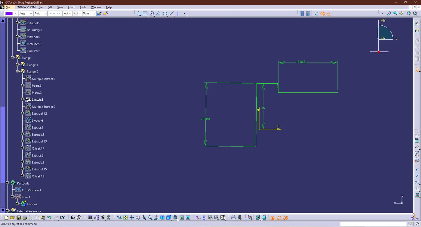
- These flanges were then thickned in the above direction to a depth of 2.5mm.
- The heat stake's surface is extracted,and the offset is adjusted to a specfic value, to create a hole in the flange.
- The angle of 0.5 deg was used to draft the hole face and the side walls.
- The front faceing verticals edges recived a 5mm fillet radius, while the remaining edges recevied a 0.5m Fillet.
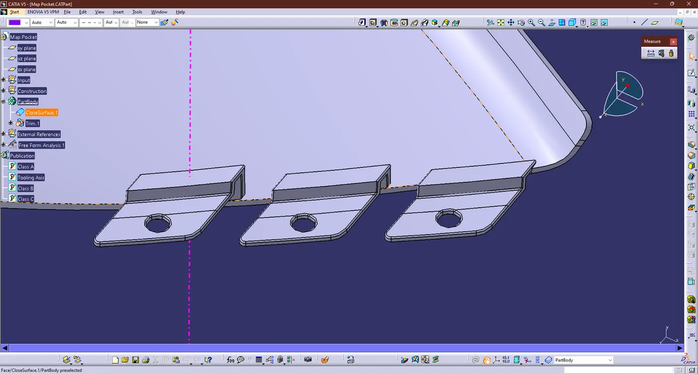
- Draft Analysis for Final PartBody:
- Same thing were do follow for the draft analysis on earlier and output mention below
- Then we got degree has 0.5deg
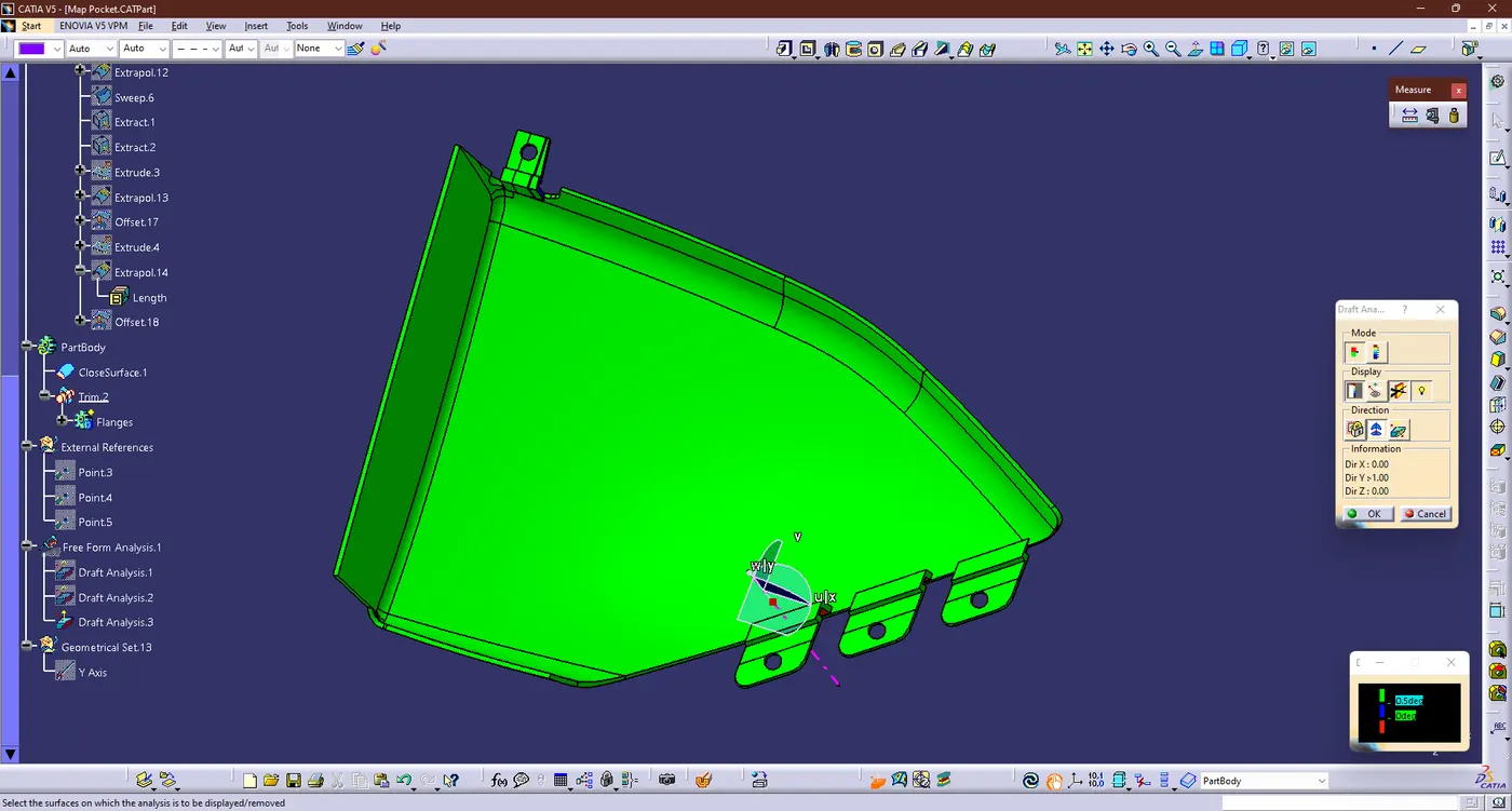
- We can see from the above draft analysis that the specified part is not as well-manufactured. A great deak of modification is required. We must ask the styling team to make specific improvement in Class A.
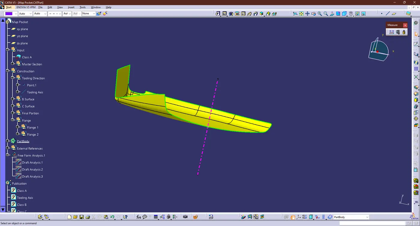
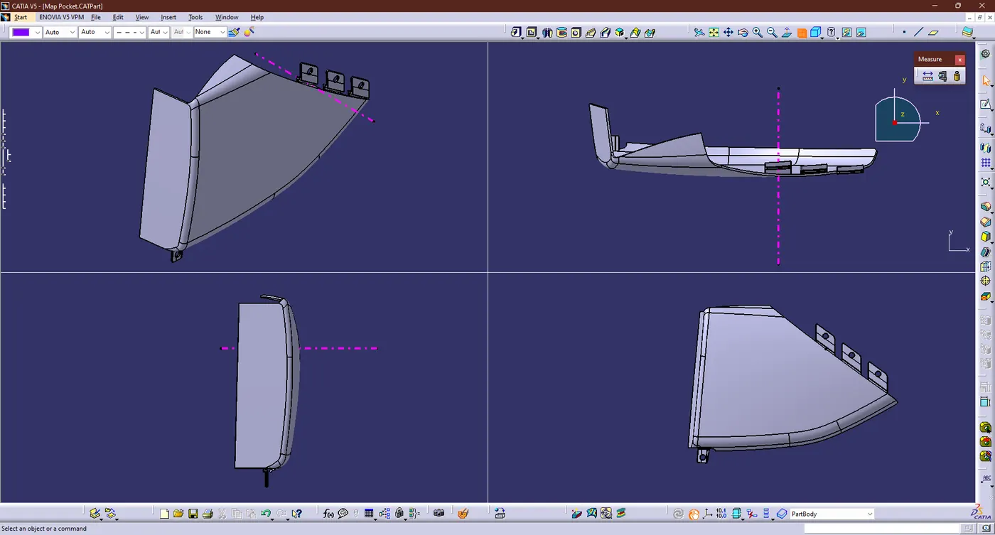
- Different Orientation of Map Pocket:
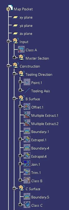
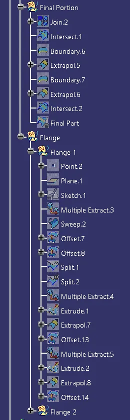
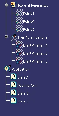
- Tree Structure:

3. BOTTEL HOLDER:
The Bottel Holder, which is designed to extend beneath the door's armrest, is intended to bottels.
Procedure For Creating Bottel Holder:
- Class A Surface:
- In given Class A have some open boundaries
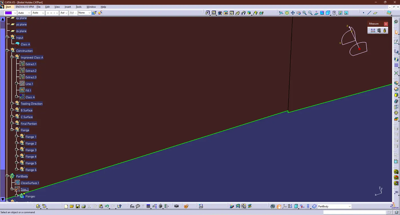
- First we need to clear the open boundaries, so i choose to Extract command to create boundary
- Then create line through the extract boundary and fill the surface using Fill Command
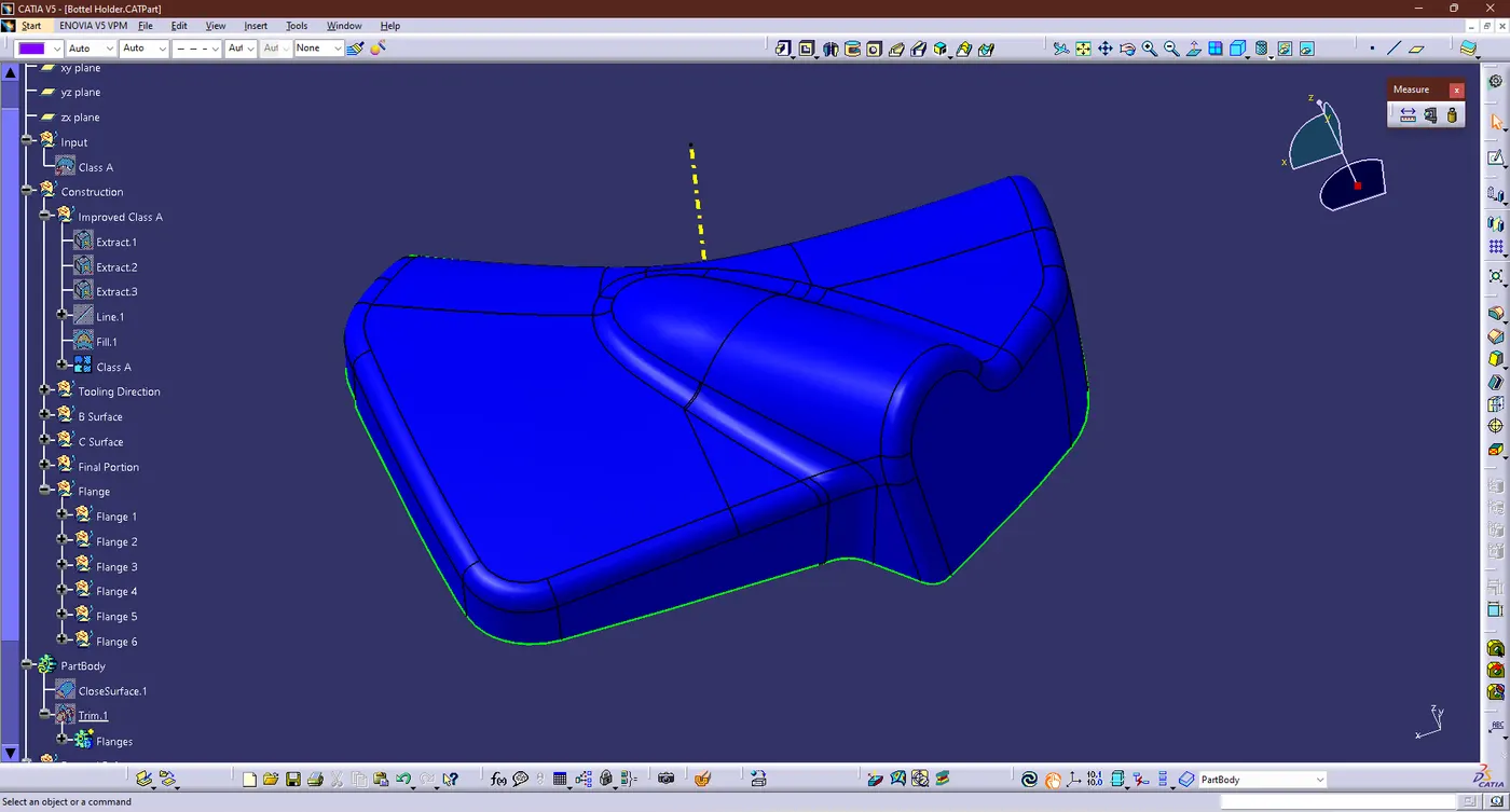
- Now we got the Imptoved Class A Surface.
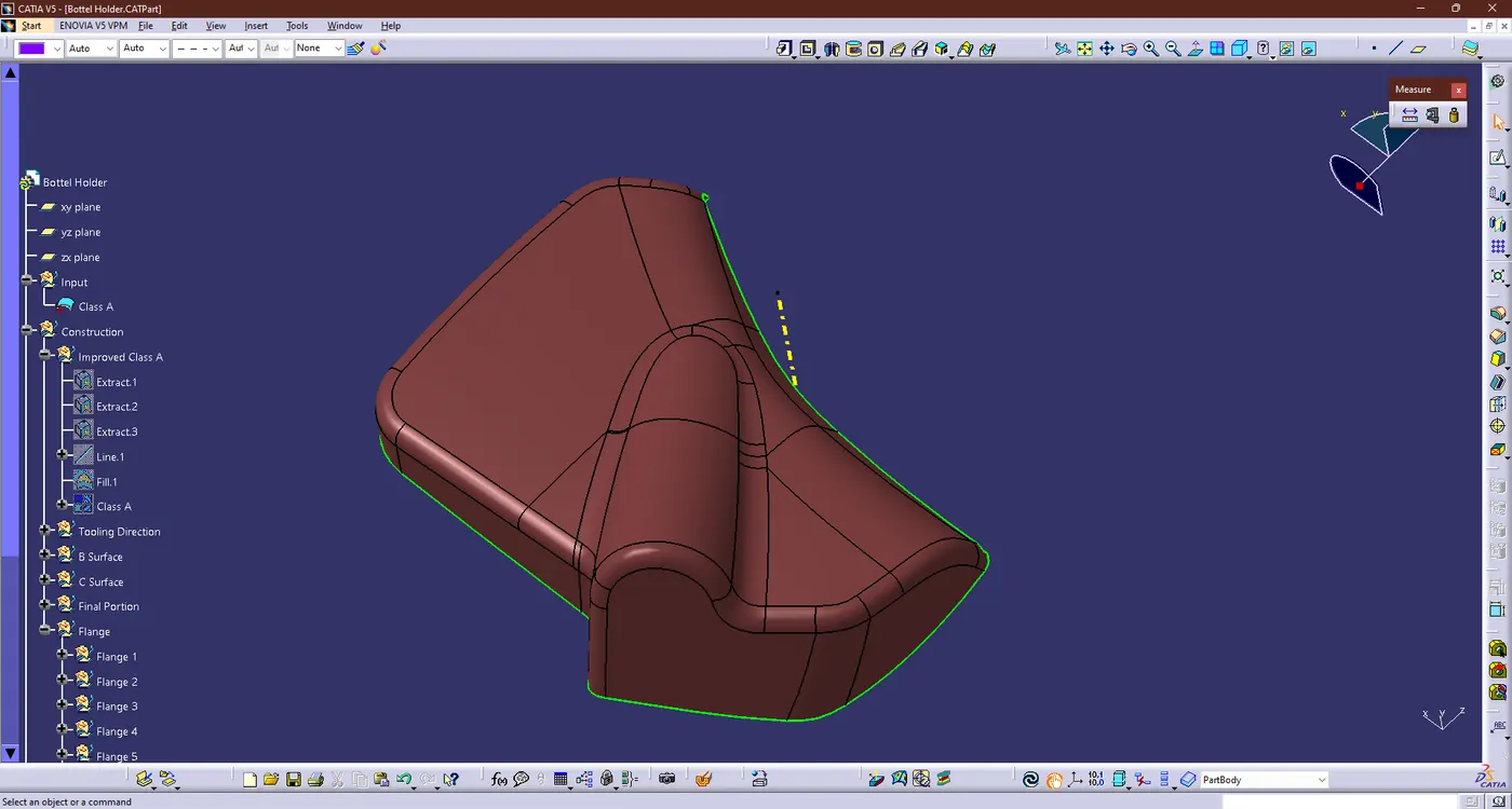
- Improved Class A Surface in Below:
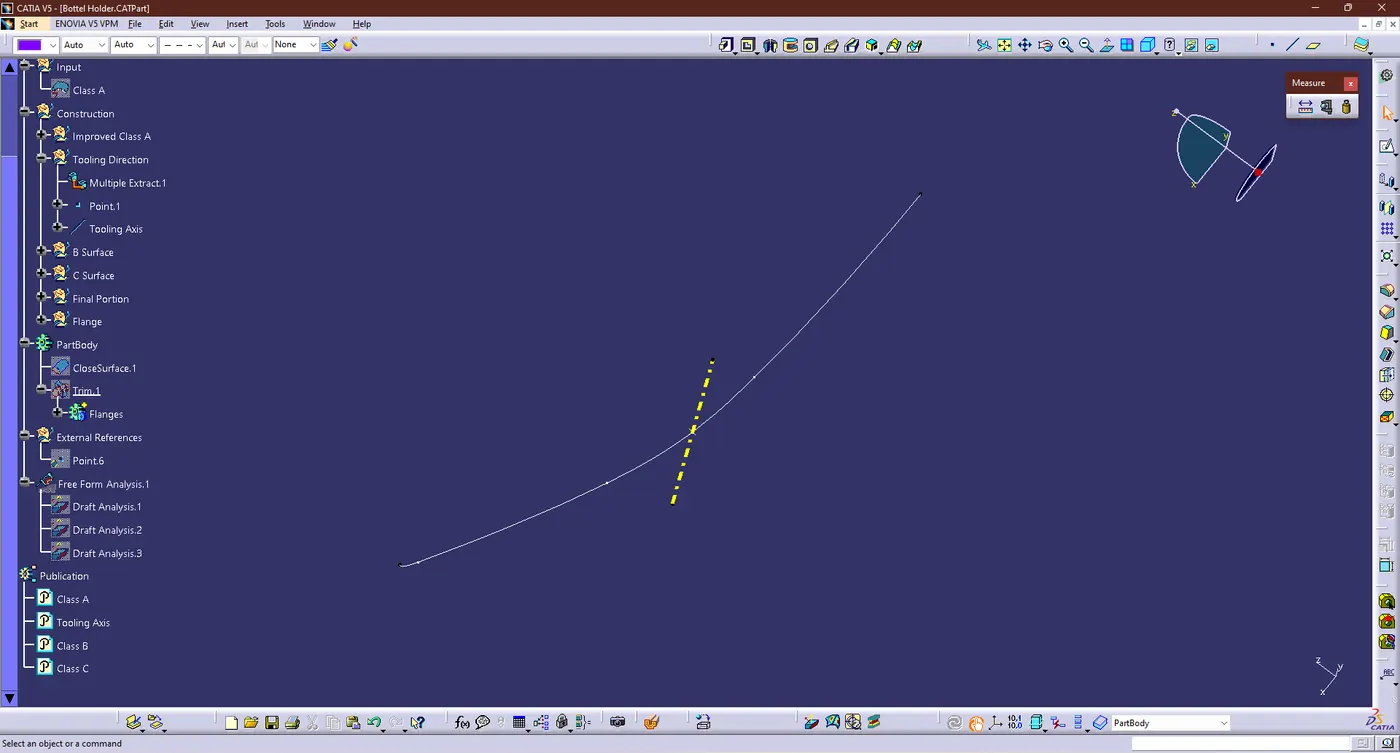
- Creation of Tooling Axis:
- The model is observed from 3 Planes and the zx plane is chosen for the details. So the curve side of Bottel Holder were chosen and a point has been created
- let create a new line in Point-Direction option Then given direction has Y axis Click ok now we got the line
- Then line given name has "Tooling Axis"
- Draft Analysis for Class A:
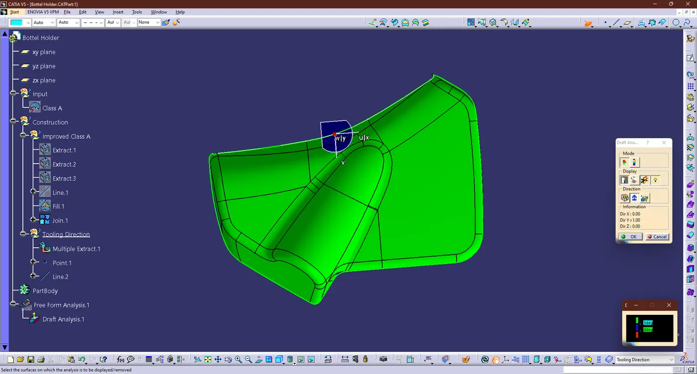
- We perform a draft analysis check for the Class A surface before we make solid part and creating features on Class B surfaces.
- Initially, I aligned the compass with the Tooling Axis and gave a Draft angle of 3 degrees for the green colour on the Class A surface.
- Creation of B Surface:
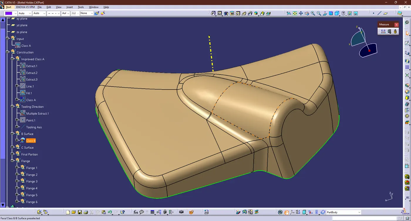
- A geometry set with name B Surface was created, then the entire CLASS A surface was extracted separately.
- Then we do Offset the extracted Class A surface with 2.5mm as per Master Section
- Now we got the B surface Map Pocket like wise mention below
- Creation of C Surface:
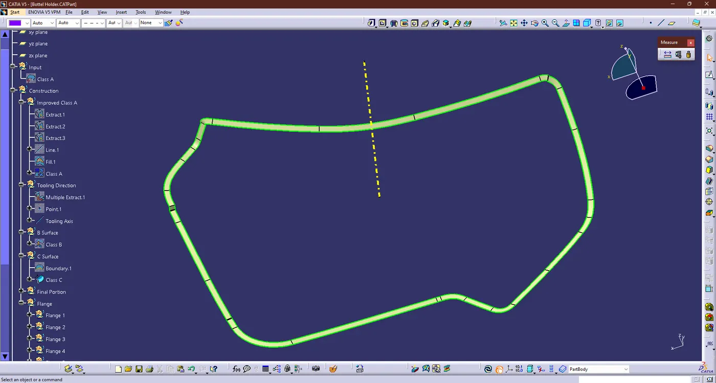
- First we need to create the boundary from the A surface for the C surface Creation.
- Now generate C Surface by using the 'Sweep' command 'With Reference Surface' option to create
- Then we got the CLASS C SURFACE like this condition
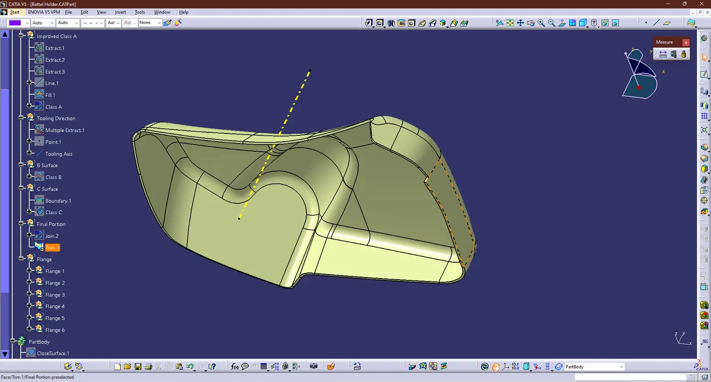
- Creation of Final Portion:
- First join the Class A & C Surfaces, using the join Command , Then trim with Class B Surface using the Trim Command
- Now we got the hollow part body of the "Bottel Holder".
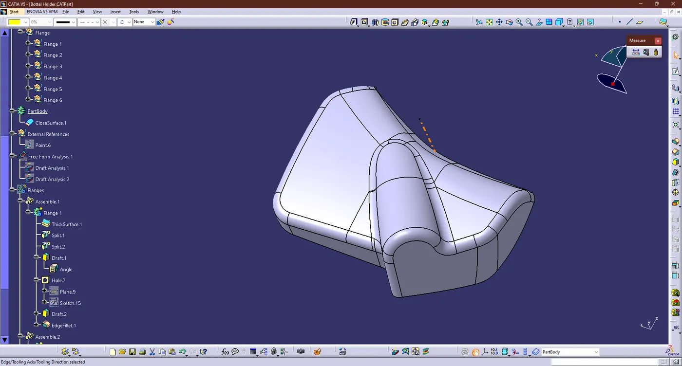
- Creation of Solid Body:
- The hollow were created as a solid by selecting the Body option and then selecting the Close body option and hence we got the final output were mention below
- Draft Analysis for SolidBody:
- In Plastic Design, the draft analysis or angle that is considered in the OEMs is 3 degree.
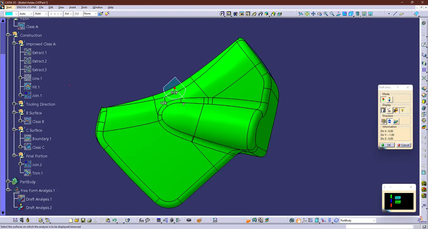
- Same thing were do follow for the draft analysis on earlier and output mention below
- Then we got degree has 3 deg
- The draft is what enables the compenent to correctly release or eject from the mold. For parts to release correctly, all parts must have a draft in the direction of mold movement. Althought most parts or applications call for a minimum 0.5 to 1 deg, 3 deg is generally acknowledged as the standard.
- Draft analysis on the solid part resulted in green, blue regions.
- The green area shows the part that can be machined or manufactured by the casting machine
- The blue area indicated that the part may be OK for some OEMs but still needs improvements for other manufactures because the draft angle is greater than 3 degree
- A red color not appearing in this case indicates that the till angle is less than 3 degrees and cannot be manufacuted or if manufacturing will be defective.
- Creation of Flanges:
- Flanges are a notion that we acquire from mastersection. In order to account for the counterpart (lower substrate) location, I made flanges on the Map Pocket.
- Where we need to create the point & Plan for creating sketch of flanges
- Then create a sketch using the Master Section and extruded then we got the Flange.
- Using planes, this trim was divided into the necessary flanges.
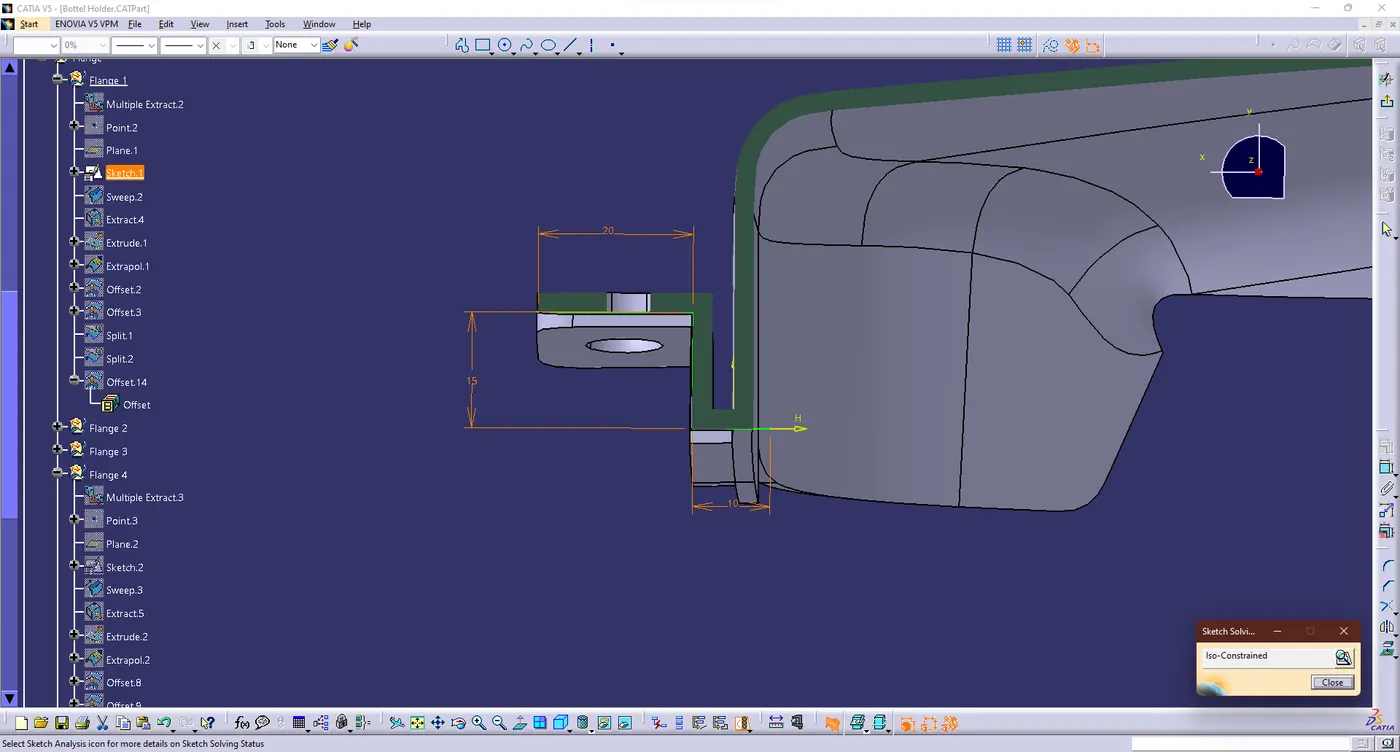
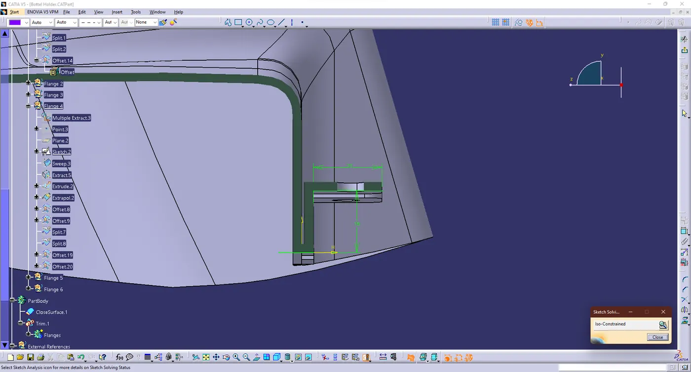
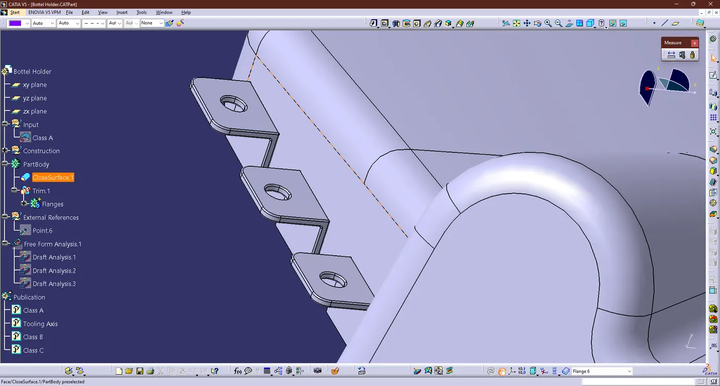
- These flanges were then thickned in the above direction to a depth of 2.5mm.
- The heat stake's surface is extracted,and the offset is adjusted to a specfic value, to create a hole in the flange.
- The angle of 0.5 deg was used to draft the hole face and the side walls.
- The front faceing verticals edges recived a 5mm fillet radius, while the remaining edges recevied a 0.5mm Fillet.
- Draft Analysis for Final PartBody:
- Same thing were do follow for the draft analysis on earlier and output mention below
- Then we got degree has 1.5 deg
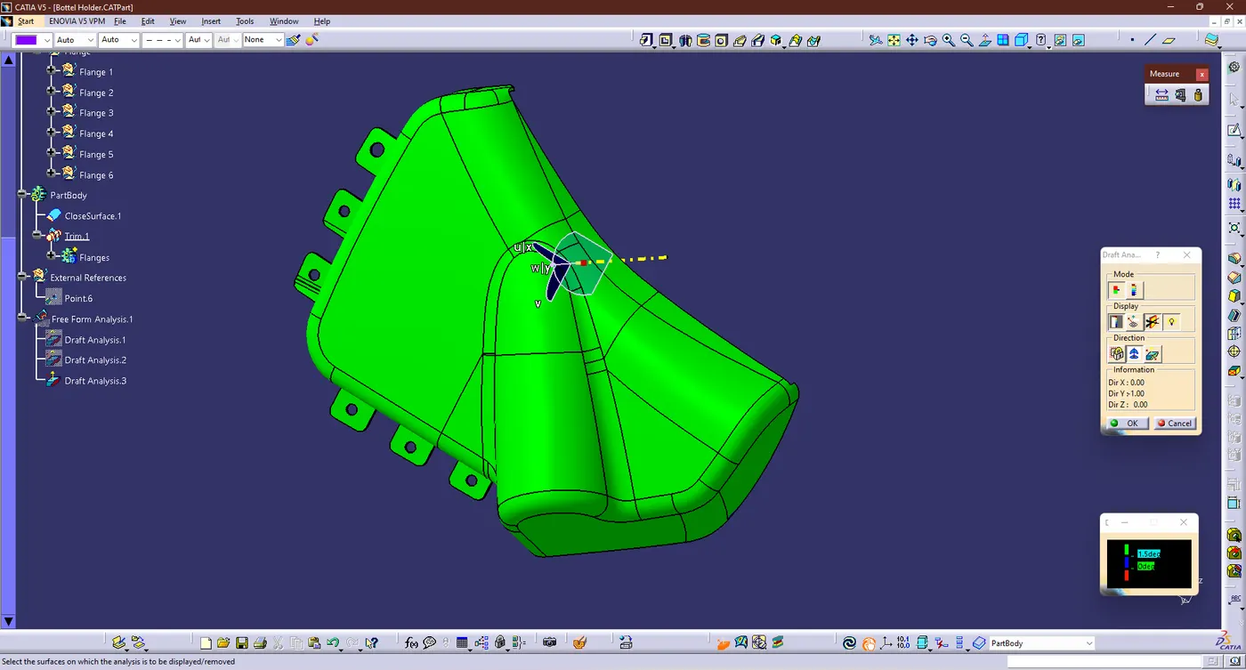
- We can see from the above draft analysis that the specified part is not as well-manufactured. A great deak of modification is required. We must ask the styling team to make specific improvement in Class A.
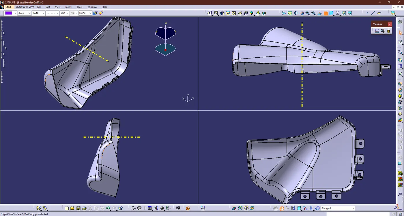
- Different Orientation of Bottel Holder:
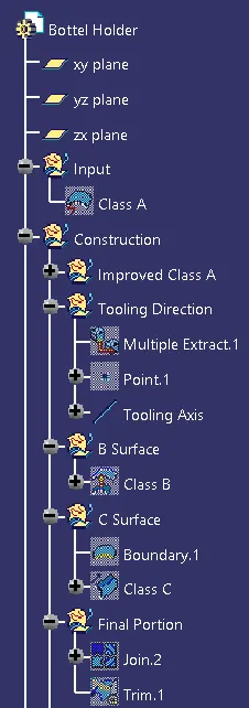
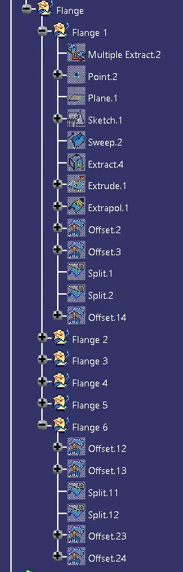
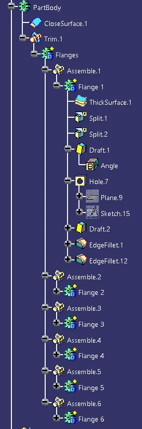
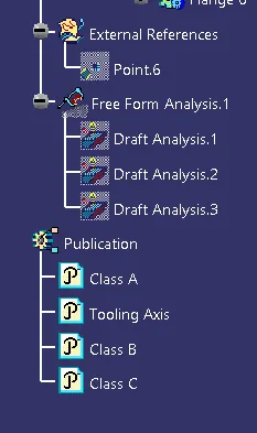
- Tree Structure:
4. LOWER SUBSTRAT:
The enclosing aesthetic part utilized in the door panel is called the lower substrate. It could have speakers, wirings, and other sheet metal components hidden underneath it, among other things.
Procedure For Creating Lower Substrat:
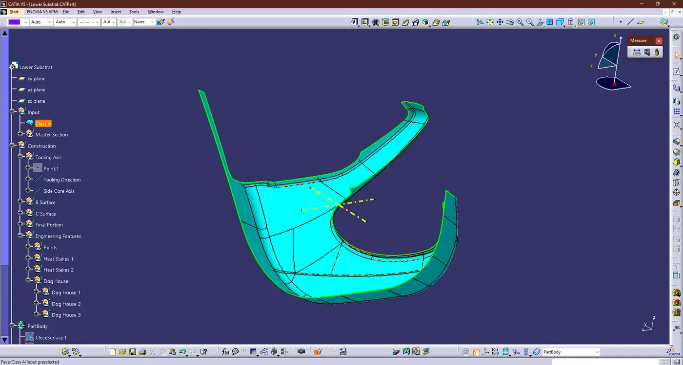
- Class A:
- Creation of Tooling Axis:
- The model is observed from 3 Planes and the zx plane is chosen for the details. So the curve side of Lower Substrat were chosen and a point has been created
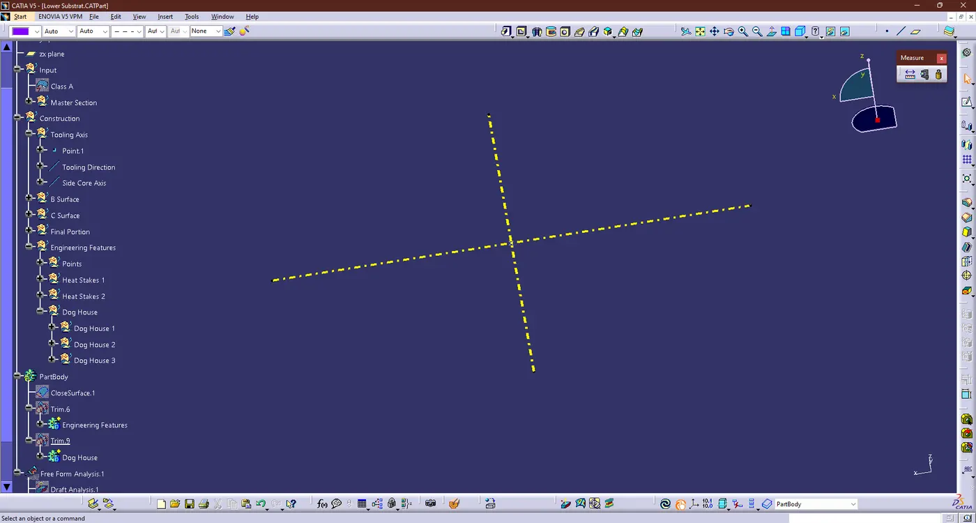
- let create a new line in Point-Direction option Then given direction has Y axis Click ok now we got the line
- Then line given name has "Tooling Axis"
- Now Create the another line for Side Core axis due to Dog House again create a line using Point-Direction option now given direction has X axis
- Those line given name has "Side Core Axis".
- Draft Analysis for Class A:
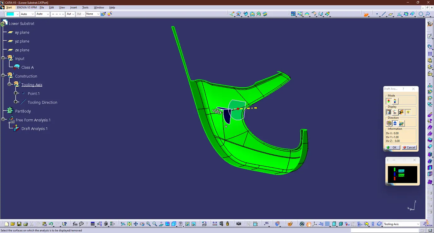
- We perform a draft analysis check for the Class A surface before we make solid part and creating features on Class B surfaces.
- Initially, I aligned the compass with the Tooling Axis and gave a Draft angle of 3 degrees for the green colour on the Class A surface.
- Creation of B Surface:
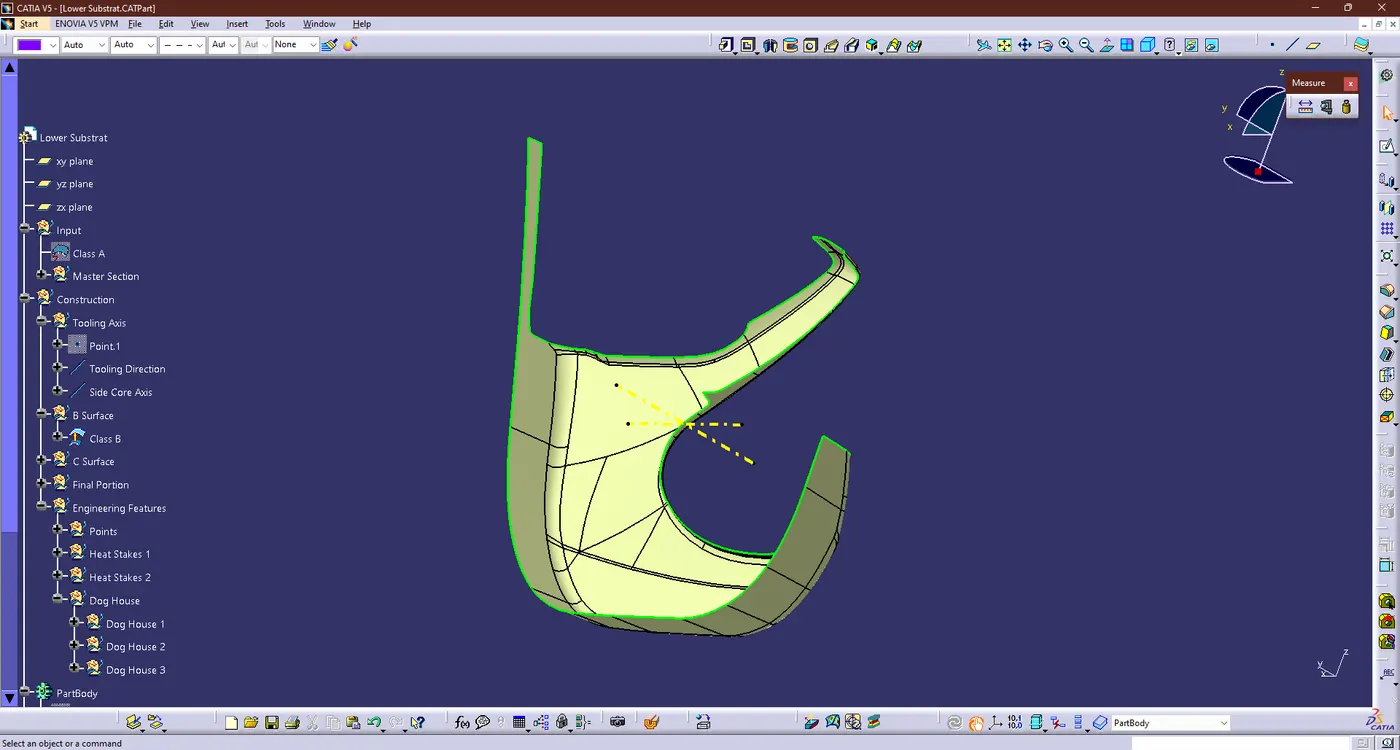
- A geometry set with name B Surface was created, then the entire CLASS A surface was extracted separately.
- Then we do Offset the extracted Class A surface with 2.5mm as per Master Section
- Now we got the B surface Map Pocket like wise mention below
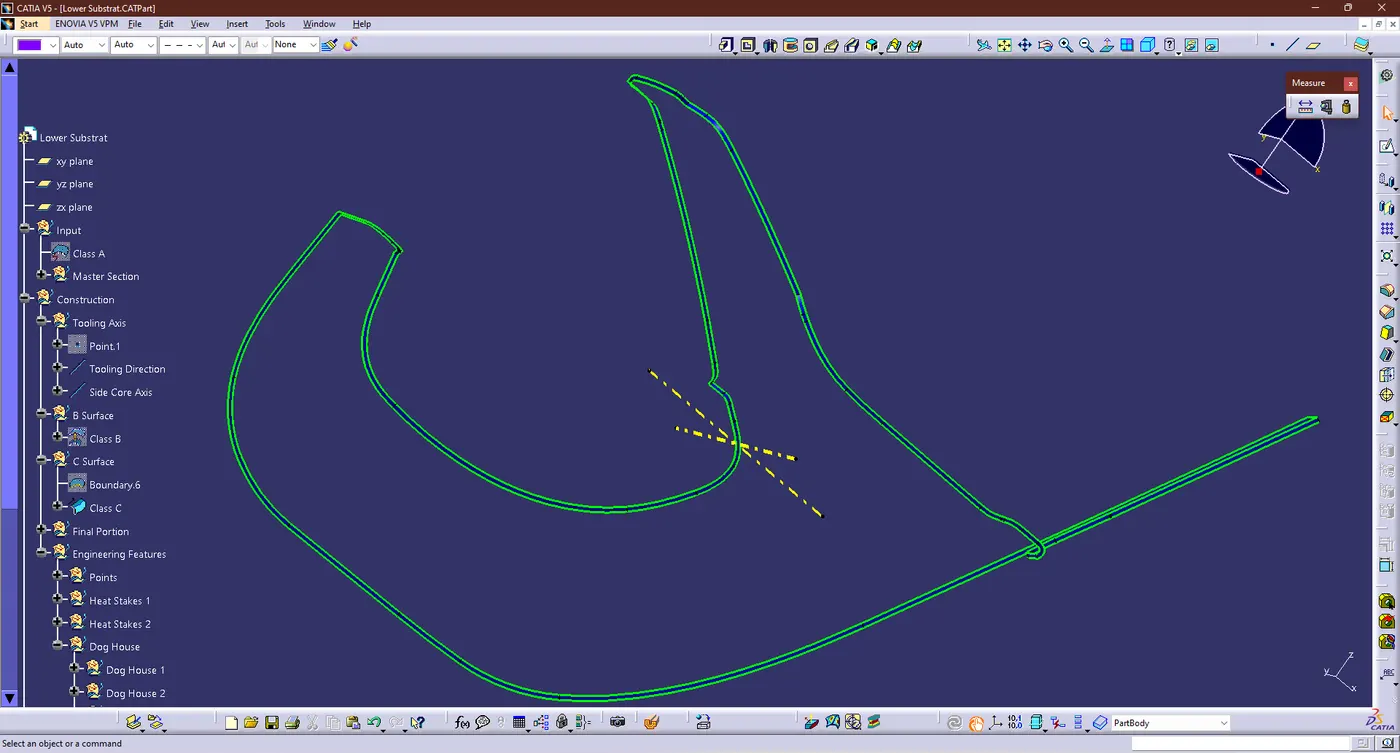
- Creation of C Surface:
- First we need to create the boundary from the A surface for the C surface Creation.
- Now generate C Surface by using the 'Sweep' command 'With Reference Surface' option to create
- Then we got the CLASS C SURFACE like this condition
- Creation of Final Portion:
- First join the Class A & C Surfaces, using the join Command , Then trim with Class B Surface using the Trim Command
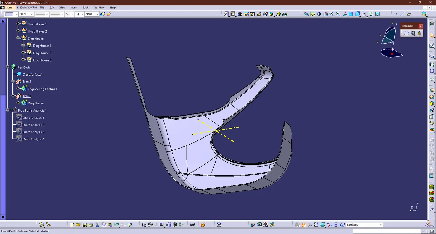
- Now we got the hollow part body of the "Lower Substrat".

- Creation of Solid Body:
- The hollow were created as a solid by selecting the Body option and then selecting the Close body option and hence we got the final output were mention below
- Draft Analysis for SolidBody:
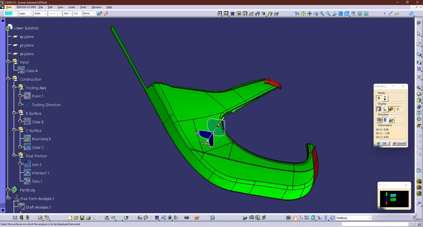
- In Plastic Design, the draft analysis or angle that is considered in the OEMs is 3 degree.
- Same thing were do follow for the draft analysis on earlier and output mention below
- Then we got degree has 3deg
- The draft is what enables the compenent to correctly release or eject from the mold. For parts to release correctly, all parts must have a draft in the direction of mold movement. Althought most parts or applications call for a minimum 0.5 to 1 deg, 3 deg is generally acknowledged as the standard.
- Draft analysis on the solid part resulted in green, blue regions.
- The green area shows the part that can be machined or manufactured by the casting machine
- The blue area indicated that the part may be OK for some OEMs but still needs improvements for other manufactures because the draft angle is greater than 3 degree
- A red color not appearing in this case indicates that the till angle is less than 3 degrees and cannot be manufacuted or if manufacturing will be defective.
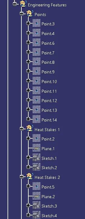
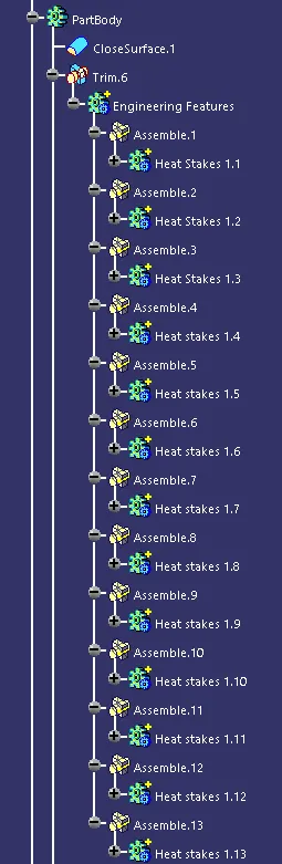
- Creation of Engineering Features:
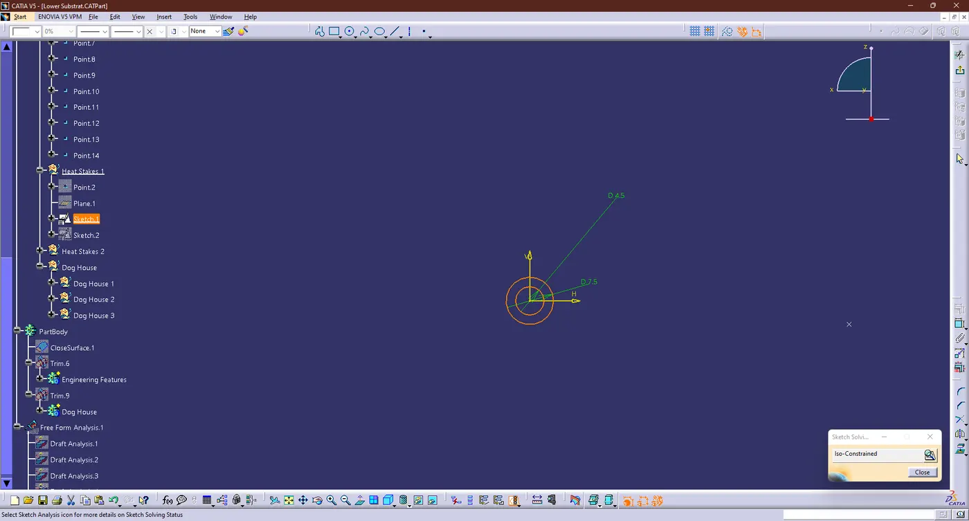
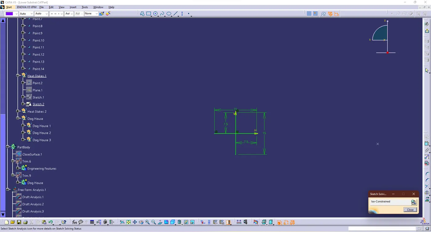
- Creation Of Heat Stakes:
- First we need to create the sketch for the heatstakes in the position sketch command in the dimension has 4.5 and 7.5 mm Dia for the circles
- Then pad the sketch using the pad command with 25.5mm height , and I draft with 0.5 deg with direction of tooling axis (inside and outside)
- After creating the heat stakes, Create the rib for supporting purposes, so do the same procedure for the rib with some tweaks like 15mm height and the thickness has 1mm
- Then draft with 0.5 deg with tooling axis and fillet given has 0.5mm for the circle portion and 0.3mm for the RIB Portion
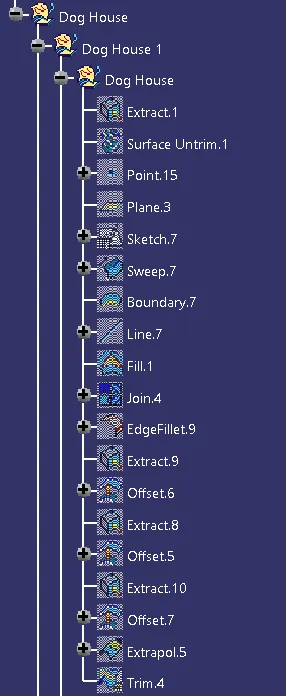
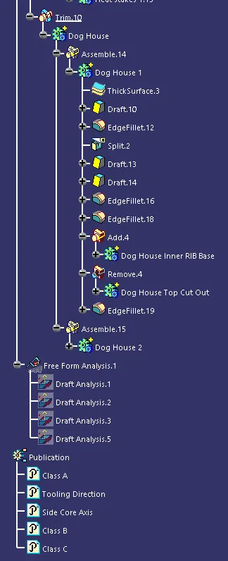
- Creation of Dog House:
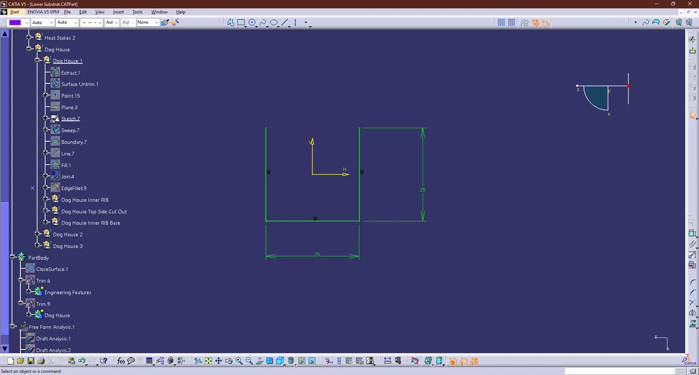
1. Creation of Dog House:
- We may draw a design Dog House to be extruded using the Sweep command.
- Then given the thickness has 2.5mm for the dog house sketch After that, we're going to provide all the required drafts using the Draft command.
- Regarding the Main Tooling axis and Side-Core axis, respectively, Draft Angle is given at the doghouse's outside and inner portions has 0.5 deg.
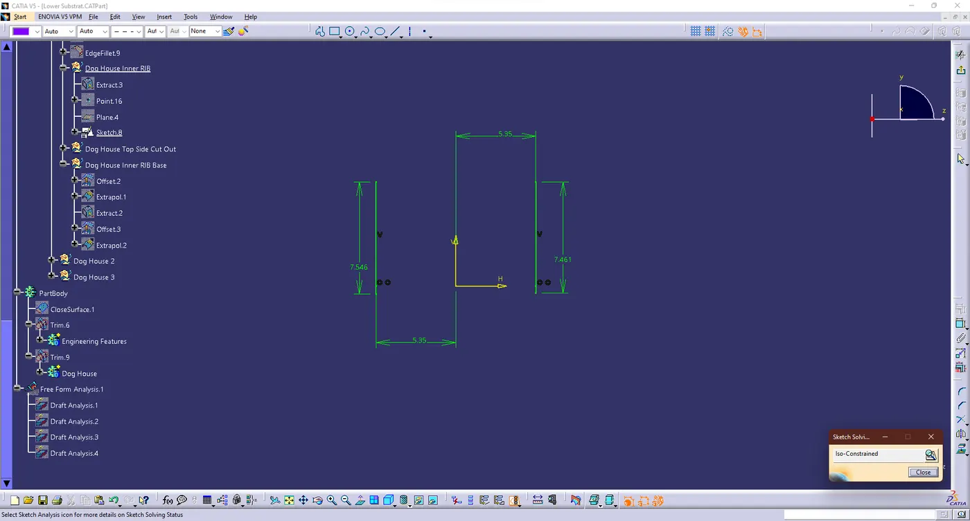
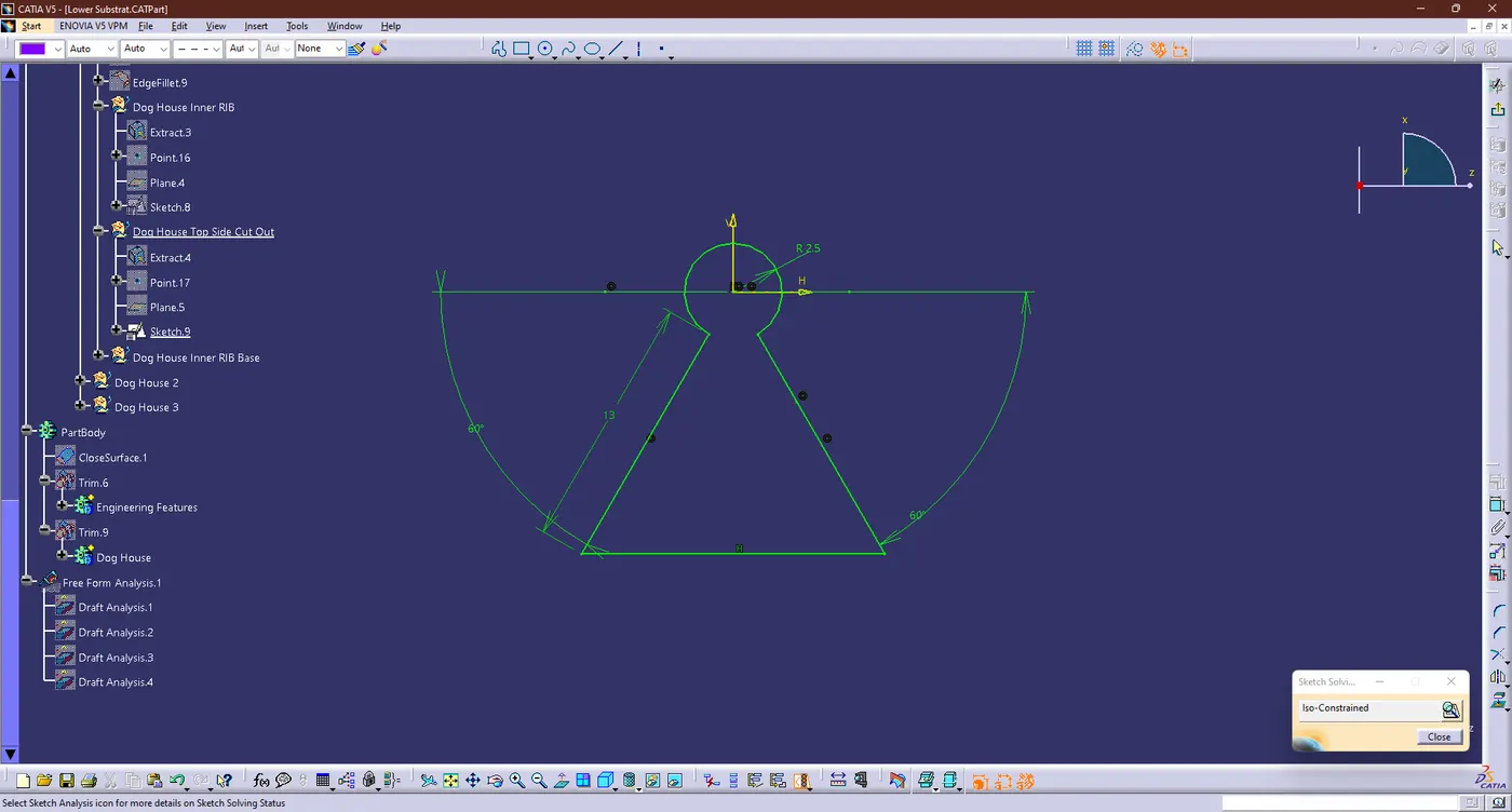
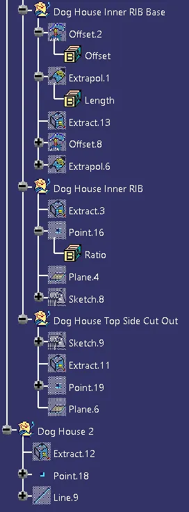
2. Creation of Dog House Inner RIB:
- We may draw a design that will allow the walls of the RIB under the dog house
- Then given the thickness for the RIB has 1mm for the RIB sketch 1&2 After that, we're going to provide all the required drafts using the Draft command.
- Regarding the Side-Core axis, respectively, Draft Angle is given at the RIB under the doghouse portions.
- Draft Analysis For Dog House:
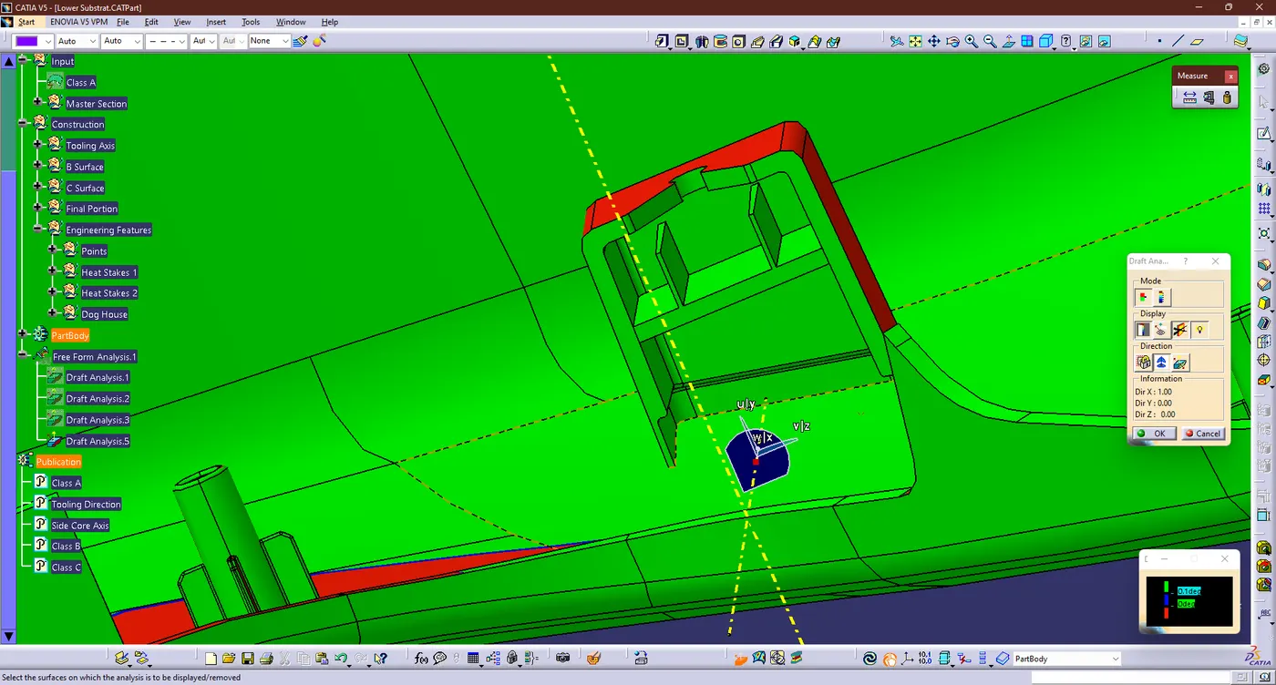
- In Plastic Design, the draft analysis or angle that is considered in the OEMs is 3 degree.
- Same thing were do follow for the draft analysis on earlier and output mention below
- Then we got degree has 0.5 deg
- Draft Analysis for Final PartBody:
- Same thing were do follow for the draft analysis on earlier and output mention below
- Then we got degree has 0.1deg
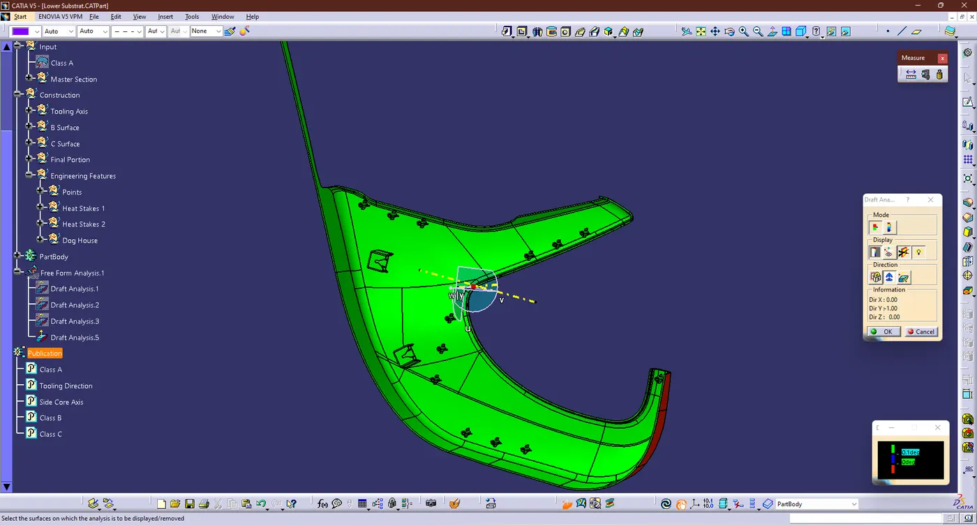
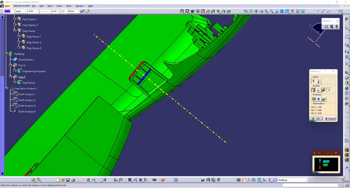
- We can see from the above draft analysis that the specified part is not as well-manufactured. A great deak of modification is required. We must ask the styling team to make specific improvement in Class A.
- Different Orientation of Lower Substrate:
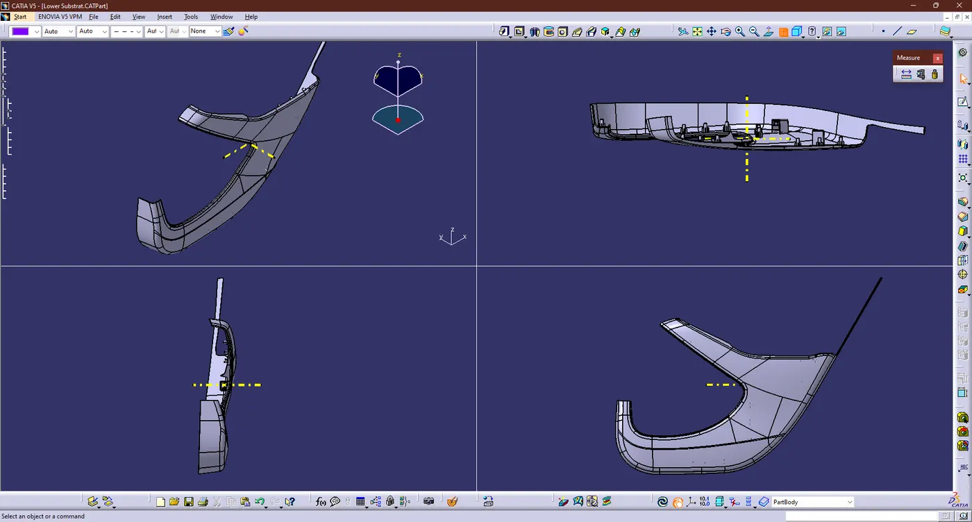
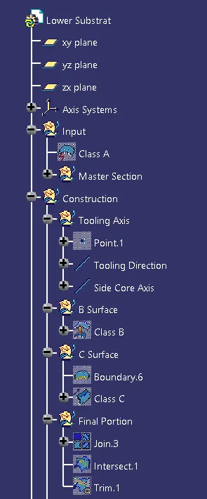
- Tree Structure:
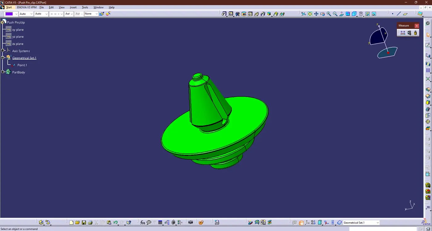
5. Push Pin/ Clip:
- Model:
6. Door Trim Panel (Assembly):
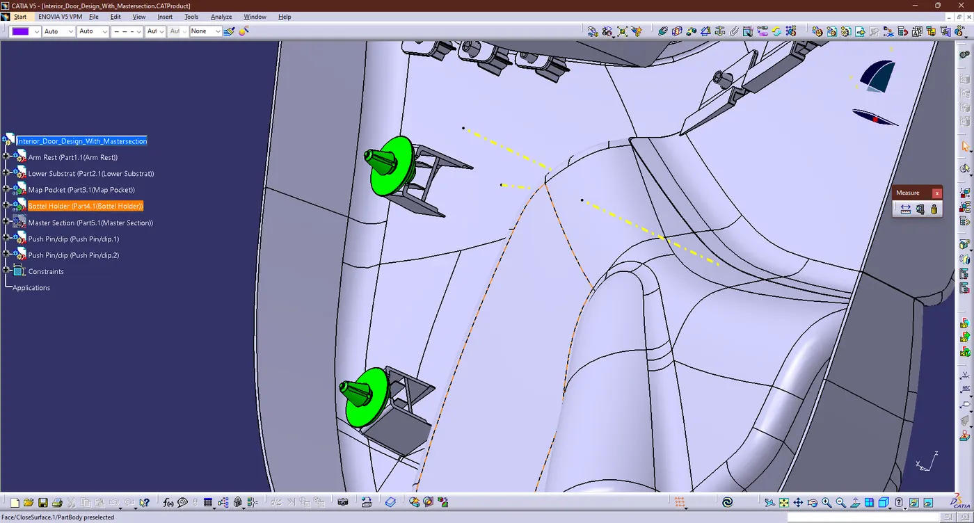
- Assembly:
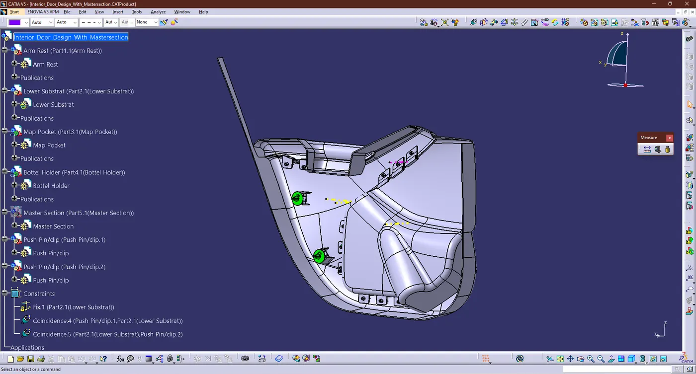
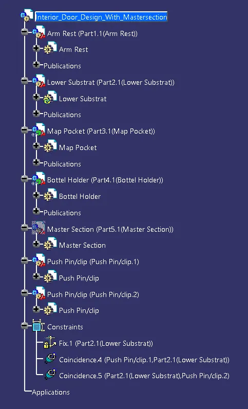
- For Final Assembly some of Part are need to constrained like Push Pin with Dog House were mention below
- Final Assemly:
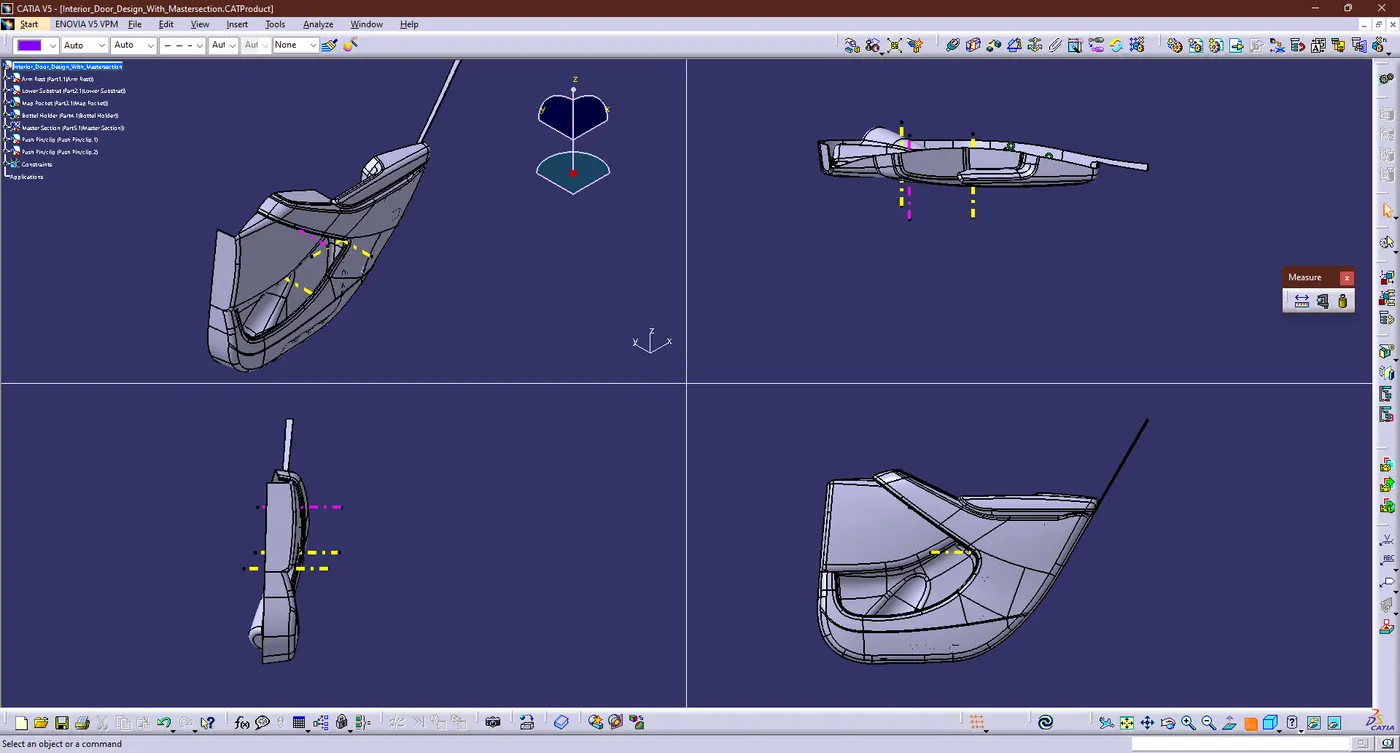
- Different Orientation:
- Tree Structure:
Conclusion:
- As a result, the Door Trim panel CAD model is produced with the OEM and Tier 1 firms' design guidelines in mind.
Files:
- Those file were uploaded in the beowse option and images also uploaded in the same zip Folder and name has "Week 12 Final Project.zip"