Project 1
- Project 1;
Develop a double-acting actuator model using Simscape Multibody and Simscape components
Aim:
To Develop a double-acting actuator model using Simscape Multibody and Simscape components. The mechanical system of the cylinder needs to be built using Simscape Multibody library components / blocks, and the hydraulic system needs to be modelled using Simscape library physical components.
Observation:
- First thing to create the double acting actuator and using the hydraulloic system and also create the multibody system
- Then combine both Multibody and actuator in single files and checking the input signal as well as the ouput signal of the model
Theory:
- The schematics show the cylinder in three configurations: half-retracted, fully retracted, and fully extended.
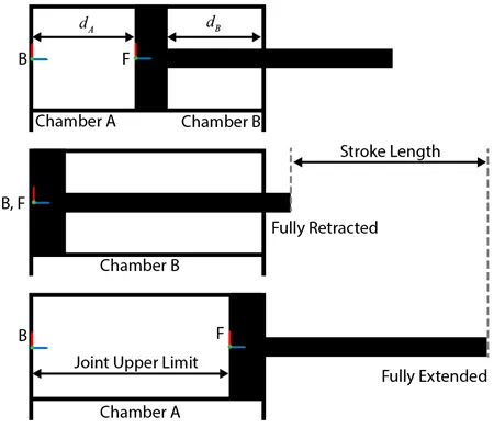
Double Acting Actuator:
A cylinder in which the working fluid acts alternately on both sides of the piston is known as a double-acting cylinder. A gland or "stuffing box" is installed in one end of a double-acting cylinder to keep the working fluid from escaping when connecting the piston to an external mechanism like a crank shaft. This hole must be made in one end of the cylinder for the piston rod. Double-acting cylinders are uncommon in other engine types, but they are common in steam engines. They are utilized in numerous hydraulic and pneumatic cylinders whenever a force in both directions is required. Each end of a double-acting hydraulic cylinder is supplied with hydraulic fluid for the piston's retraction and extension. A double-acting cylinder is used when the piston cannot be retracted by an external force or when both directions of travel require a lot of force.
Model:
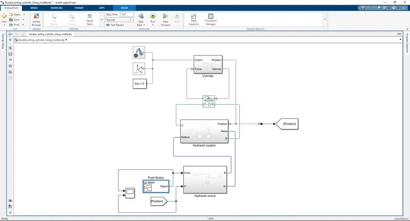
- The above model as the developed double acting actuator using simscape multibody and simscape components
- First of all to create a blank model from the simulink and there we need basic component to identify the multibody system
- The model as the need mechanism Configuration it should set the mechanical and simulation parameter of the developing the model
- Then we need world frame this should had ground or the world for model and also need solver configuration it should to Defines solver settings to use for simulation
- Multibody Systems (Cylinder):
- In this section there are two part avalibale there are cylinder assembly , Piston assembly and also prismatic joint also in this section
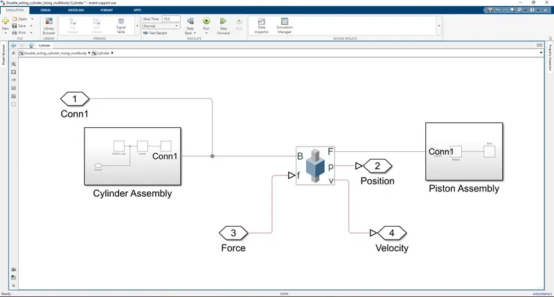
- First we create the cylinder assembly
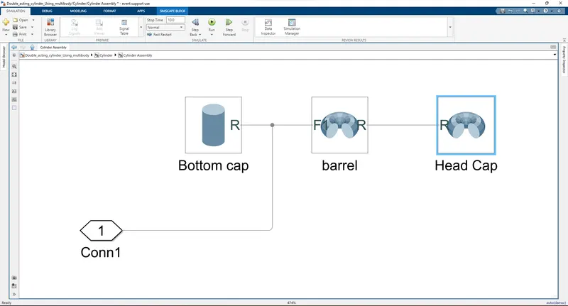
- The above image it refer the cylinder assembly in this section there three componet were use and mention below
- First i choose cylinder solid for the bottom cap and and the values were mention below
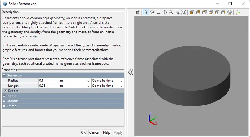
- Then i could create the Barrel and those valuse also mention below in this barrel i choose the revoled solid for the we need inner circle also i choose this one
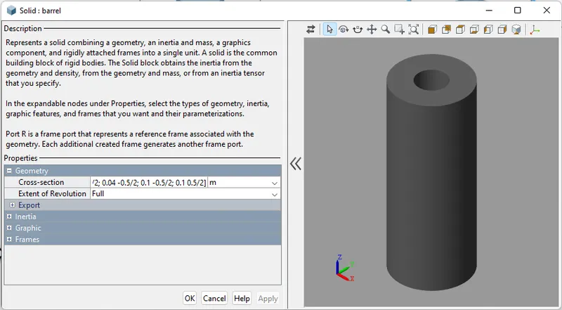
- In the cylinder assembly last part as well as the head cap and same as revoled solid are used in the head cap also and those values were mention below
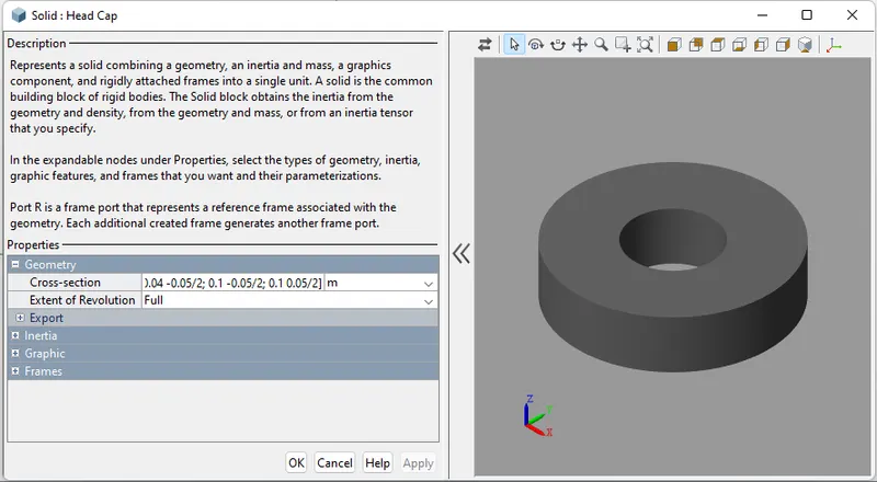
- Then we see the Piston assembly and also see the prismatic joint those the values are mention below
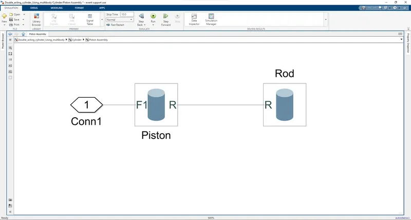
- It has the Piston assembly for the double acting actuator
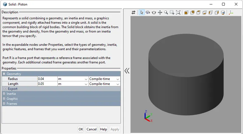
- The above image it refer the piston of the cylinder and values are mention in the image it usinf cylinder solid
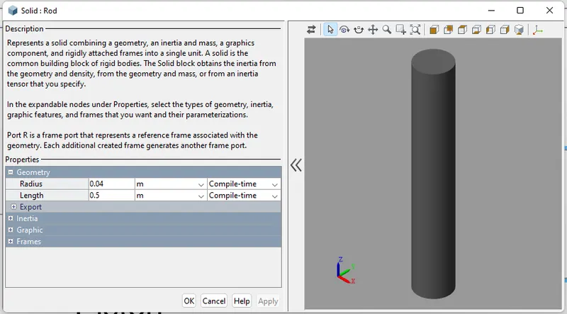
- then the rod were created and same as well as th cylinder solid also used in the piston rod
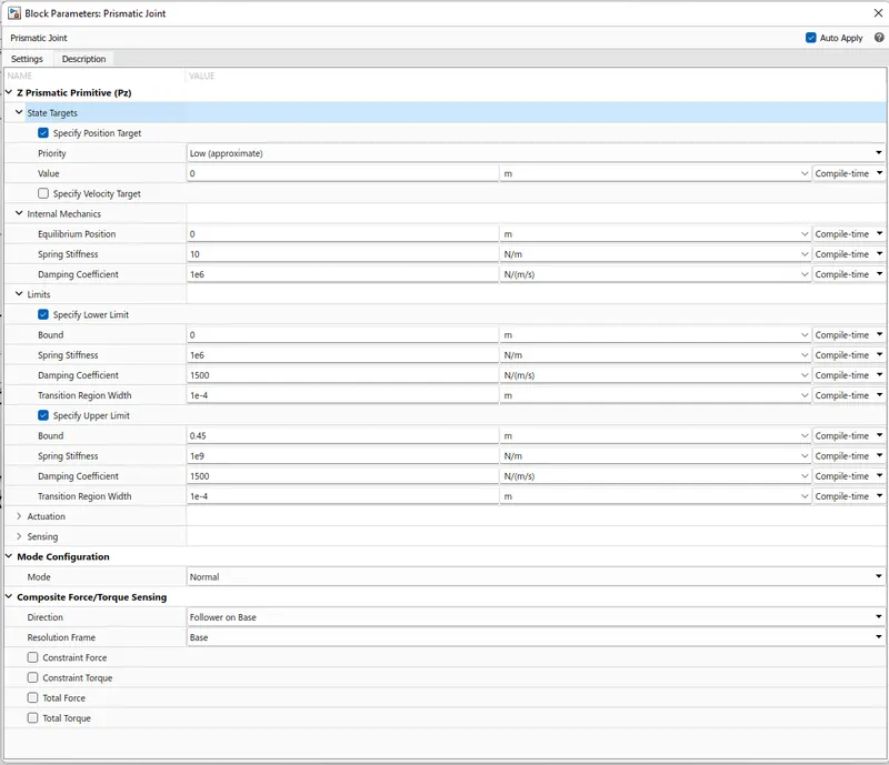
- Then finial the component of the multibody sytem aka cylinder has the prismatic joint and those valuse were mention below in the format of the image and those other componet also mention below
- Then it represent the two joint between the two frames
- Hydraulic System:
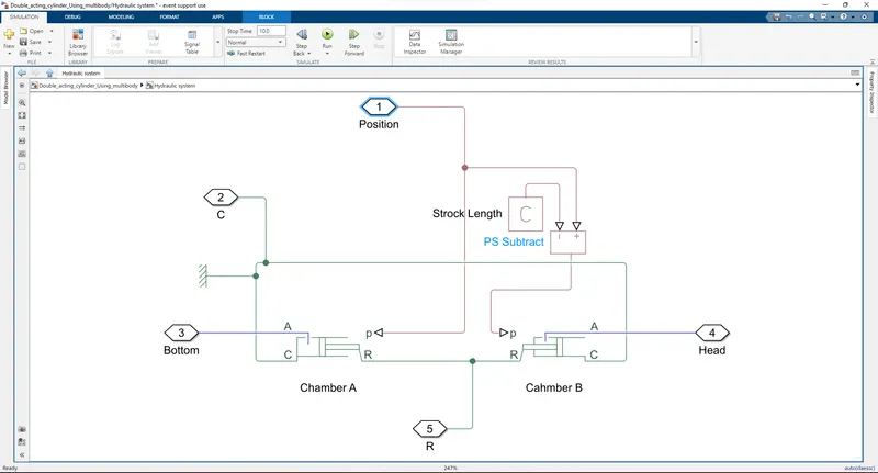
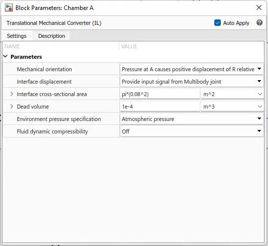
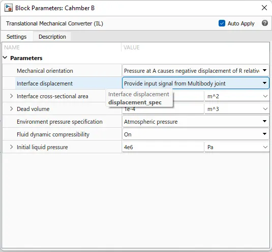
- In this hydraulic system there are two actuator were set up in the form of Physical system and named as the chamber A & B
- Those Chamber were connected through the Translation multibody interface through the Cylinder
- Chamber A
- Chamber B
- Hydraulic Circuit:
- In the section consist of the heart of our system because of the hydraulic liquid used in this sectiion and also given input as the signal builder then convert the simulink to physical system
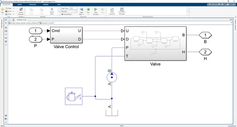
- In this part there are some othe section avaliable there are valve control and valve and also i used isothermal liquid used in this model
- First we take look on Valve control in this section there are some convertion it should happed in the in those were input
- the input were given in the form of signal bulider why we this for the accurate signal as well as the output of the sources those valve control image were mention below
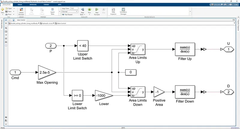
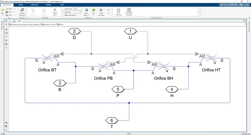
- Then create the valve in this section i choose orifice in the term for the hydraulic flow of the system and the image mention below
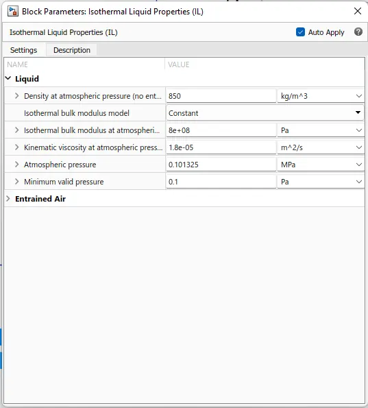
- Then we need isothermal liquid for the system working and also need pressure source both are used in this section
- Connection
- First the Cylinder section there are four port avalible there are input of the basics element, position, force and velocity
- Those force and velocity were connected through the translation multibody interface, in this interface there two port are avaliable named as C and R for the Hydraulic system
- In the Hydraulic system also have C and R were connecte throught the interface then position were connected throught the cylinder then balance port were bottom and head were connected throught the hydraulic circuit
- those hydraulic circuit also have some of port named as the Cmd, p ,B and H
- In Cmd means input signal were given through the port, then p is the position it has feedback system of the model those were connected throught the position of the cylinder
- Then balance B means bottom and h mean head were connected throught hydraulic system
- Output:
- In this model were scope also connected nearby the input signal and the input signal were data were mention below
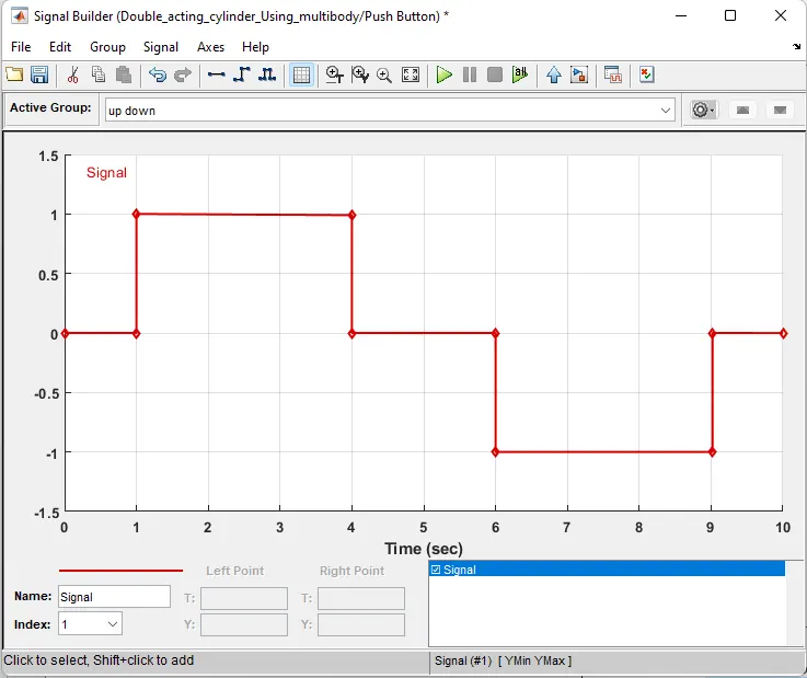
- Then the output has same as well as the input and checking the i working as normal as per given instruction and the output were mention below

- Output (video):
- In multibody section they were create the video format output also uploaded in below in the format of link
- Link
- Video format Output
- Files:
- The above model file were uploaded in the name of Double_acting_cylinder_Using_multibody_1.mdl
- Then the output also uploaded name of Double_acting_actuator_cylinder(output).png
- Video format output also uploaded in the name of Double_acting_cylinder_Using_multibody(Video).mp4