Project 2
Project - 2:
Development of a forward energy-based fuel consumption model of a P1 hybrid vehicle
Aim:
- Computes fuel consumption values for a given vehicle (kmpl) in city cycles (UDDS) and highway cycles (HWFET). It also analyzes and understands the vehicle's operating point in terms of engine speed, torque, transmission speed, pedal position, gear, mileage, and more.
- To create the simulink model using the block as per needed and completed the Electric motor, Crank Hub, Mode selection
- Then return the script file for the matlab and load all variable need to run the simulation file
Objectives:
- Tabulate the fuel economy numbers (kmpl) for UDDS and HWFET cycle. Compare these numbers with the baseline numbers for conventional vehicle model from Project 1.
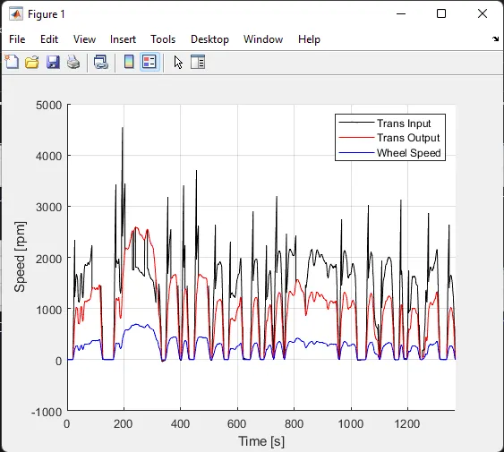
- Plot the time trace for engine, transmission input, transmission output and wheel speed on one plot.
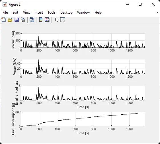
- Plot engine torque, engine power, fuel rate and fuel consumption using subplots.
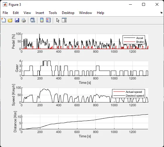
- Plot accelerator and brake pedal, gear command, vehicle desired and actual speed, vehicle distance using subplots.
- Plot the engine operating points on the engine fuel map.
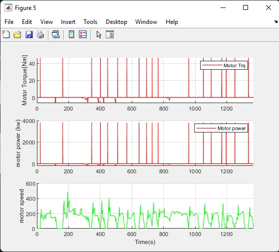
- Plot motor speed, torque, motor input power using subplots.
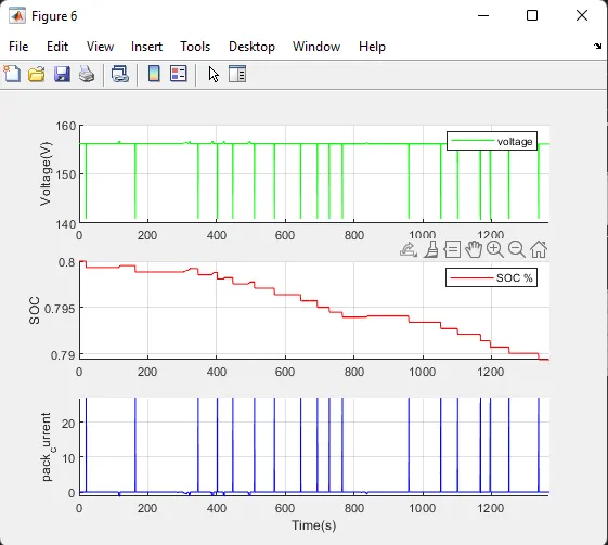
- Plot pack voltage, current and SoC using subplots.
- Plot the motor operating points on the motor input power map, with the motor max motoring and generating torque curves.
- Write down appropriate brief comments on each of these plots, describing the vehicle behavior throughout the drive cycle.
- Generate the plots for both drive cycles
Theory:
- Hybrid Vehicle:
- A hybrid vehicle is a vehicle that uses two or more different types of energy, such as: B. A submarine that uses diesel on the surface and batteries when submerged. Other means of storing energy include pressurized fluid in hydraulic hybrids.
- Hybrid powertrains are designed to interchange from one electricity supply to any other to maximise each gas performance and electricity performance.
- For example, in a hybrid electric vehicle, the electric motor is more efficient at generating torque and rotational power, while the internal combustion engine is better at maintaining high speeds. Increased efficiency, reduced emissions, and reduced running costs compared to non-hybrid vehicles are his three key benefits of hybridisation.
- System Dynamics:
- Address the modeling of multidomain systems using a unified approach based on ordinary differential and algebraic equations describing static and dynamic effects.
-
Each systems has are two generalised variables-
1. Efforts:- It is generalised force variable. ex- torque, force, voltage, heating value.
2. Flow:- It is the generalised flow/velocity variable. ex:- velocity, current, mass flow rate.
3. Power:- It is the product of the effort and flow variable. It is interchangeable between energy domains.
- Energy based models- Element models:
- There are basically two approaches to modeling the internal physical properties and losses of elements.
1. Map based models:
Elements are modeled using maps that characterize the relationships between inputs and outputs, outputs and losses, and so on.
2. Analytical models:-
Elements are modeled using physical equations that describe their internal dynamics. These are extremes, most models are a combination of both, and some models use dynamics models analytically or for maps.
- Forward Model:
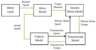
- Forward model otherwise called as dynamic simulation. These were used for the detailed simuation
- Force/Torque/Power are the input and the Vehicle state variable velocity and accleration are output
- Model and Simulation are more realistic due to physical construction hence appropriate for control development
- There is a feedback loop to meet the desired vehicle state and there are slower simulation due to the dynamics
- Approach's mainly used to simulate a vehicle on a drving cycle to analyse the dynamic behavior of the system, helps signigicantly in control development
- Below image reperesent about the architeccture of the forward conventional vehicle model
Vehicle Model:
- In this Project, Honda Insight motor and battery are considered for this project. Data is taken from ADVISOR data base developed by NREL, USA. Data provided in the project files.
- The developed models can simulate vehicles in different driving cycles such as UDDS, HWFET, FTP, NEDC.
- Pre-Processing:
"Project2_InitFile.m" is a Matlab script used to load all the variables required for running and post-processing the Simulink model. The drive cycle is also selected here. Run this initialization script before running the Simulink vehicle model.
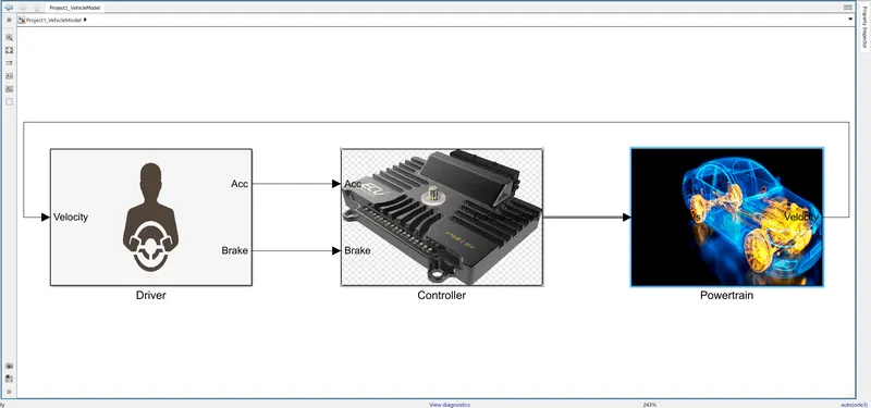
- A Simulink model of the convection model is built with three main sub-blocks: Driver model, controller model, powertrain block.
- Actual vehicle speed is provided as feedback to the driver block, which provides the required acceleration or braking force to the control block. Control blocks provide engine torque, gear shift, and braking torque control signals to the powertrain model. make.
- Driver:
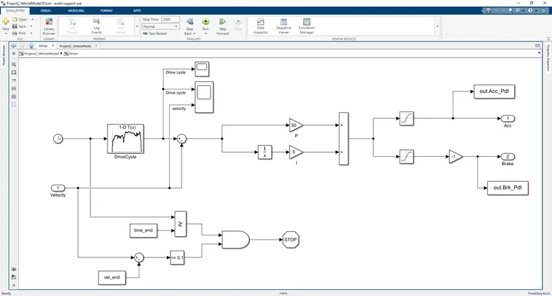
- The driver model is a basic PI controller that generates accelerator and brake pedal outputs to match the desired and actual vehicle speed.
- Based on these consumption and emissions results, the vehicle uses a certified driving cycle and forms a uniform standard for evaluation. It is based on time and speed, all integrated to generate the output accelerator and brake pedals.
- Controller Unit:
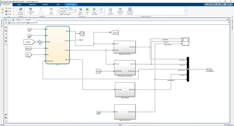
The controller block is the brain of the vehicle, representing the electronic control unit that produces the required engine torque, transmission gear and brake torque based on driver input. These inputs are sent to the "Powertrain" block, which represents the vehicle's powertrain.
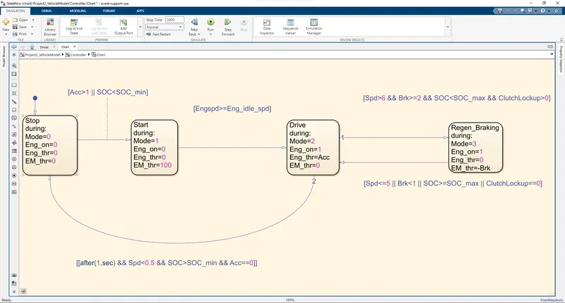
1. Mode Selection:
- State flow machines are used to represent supervisory controllers that determine operating modes.
- During start/stop mode, driving mode, and regenerative braking mode. motor drive in each mode and
You can control the motor drive.
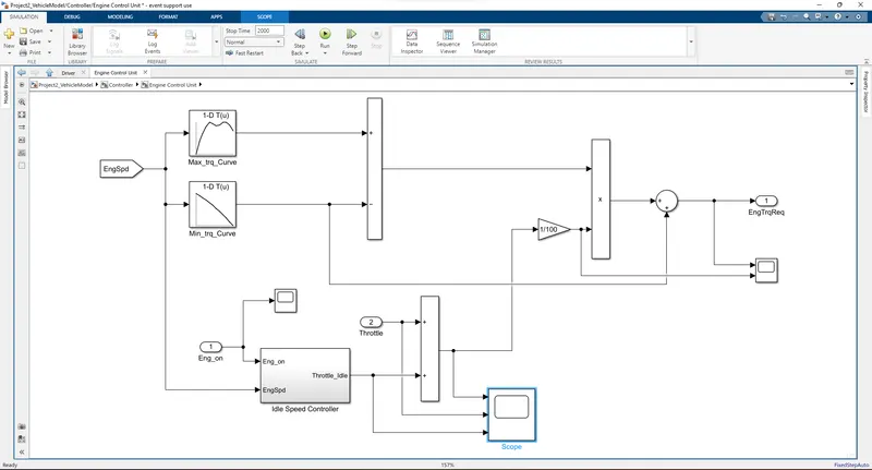
2. (a) Engine Control Unit:
- Engine Controller Compares engine speed to the maximum and minimum torque curves in the lookup table and gives the required torque command to the engine block.
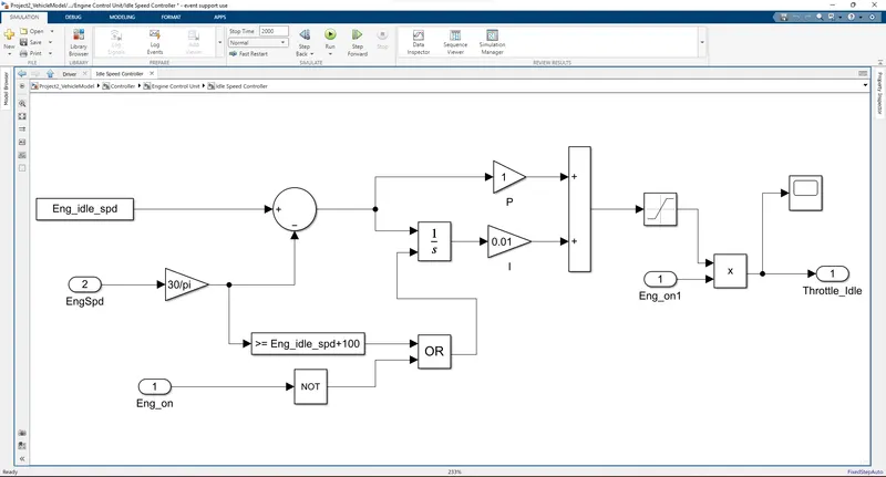
- The throttle input is combined with the idle speed throttle and the torque output from the lookup table is used to increase the gain to estimate the required torque input to the engine.Gas input, idle gas and their totals can be obtained from this block.
(b) Ideal Speed Controller:
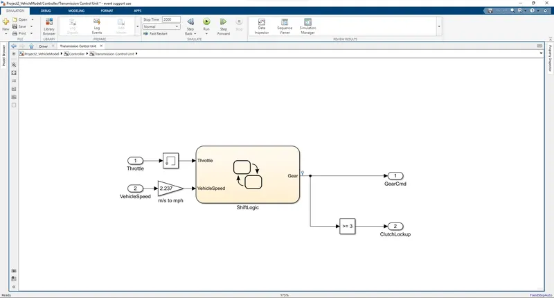
3.(a) Transmission Control Unit:
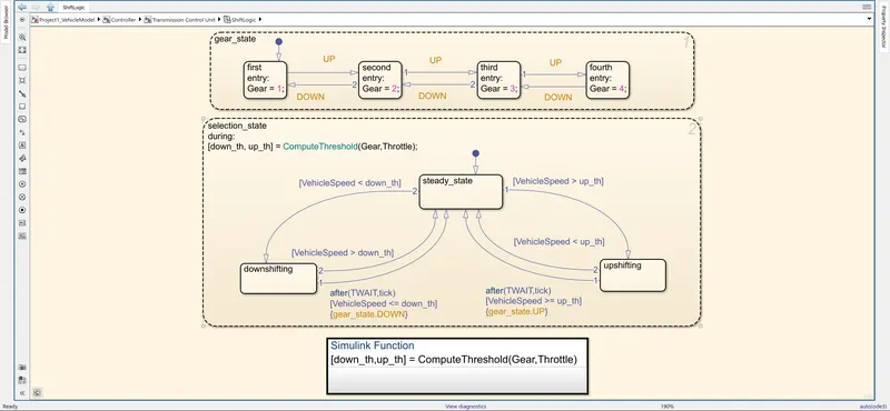
- This block conntrol the gear shifting using study flow variable chart
- Controls shifting according to vehicle speed and throttle input.
(b) Shift Logic:
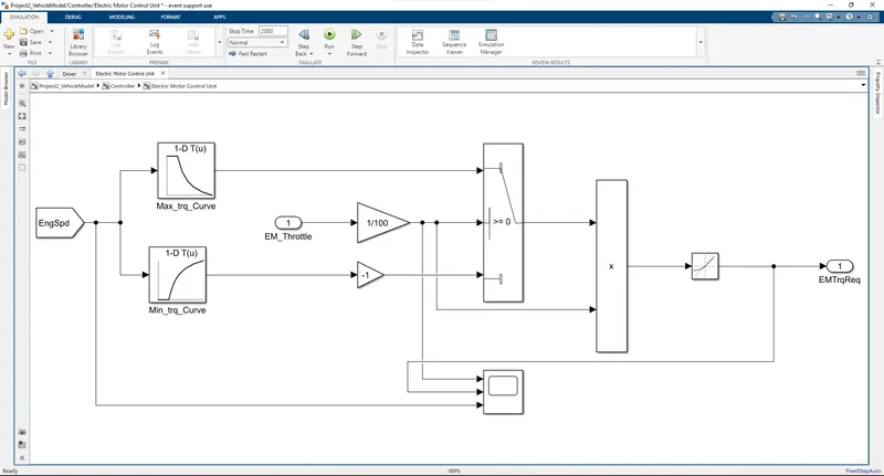
4. Electric Motor Control Unit:
- The motor control unit EM speed is compared to the maximum torque curve and maximum torque production curve in the lookup table to give the required torque command to the electric motor.
- Use the EM throttle input to compare a lookup table to estimate the required torque input for the E-motor.
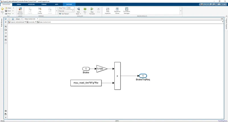
5. Brake Control Unit:
- Brake Control Unit Generates the required braking torque in response to brake pedal input and transmits braking torque to the wheel blocks in the transmission model.
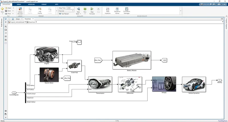
- Powertrain Unit:
- This unit do conversion of the given input to the desired output like we given input as the fuel in the form of chemical energy that convert into the mechanical energy in the form of the vehicle movement
- This block consist of the Engine, Electric Motor, Crank Hub, Transimission, Differential, Wheels, Vehicle Dynamics, and also Battery Module For storing power and suplly to the electric motor
1. Engine:
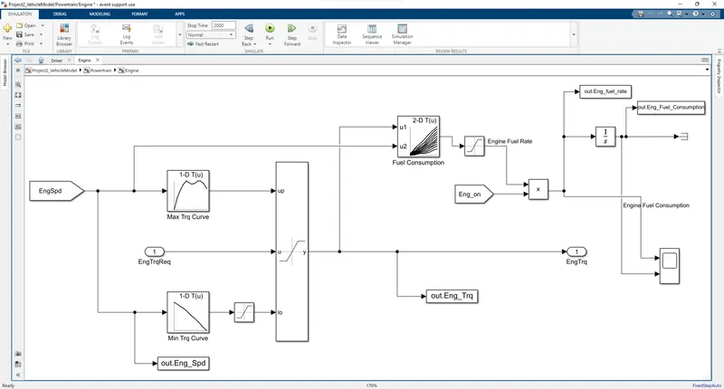
- Based on engine speed, the required torque from the controller saturates between the maximum and minimum torque curves, passing engine torque to the transmission block.
- A 2D lookup table is used to calculate fuel flow based on engine speed and torque. The fuel flow is then integrated to determine fuel consumption.
- The estimated fuel flow, fuel consumption, engine torque, and engine speed are passed to the MATLAB workspace using the To Workspace block.
- Engine fuel flow and fuel consumption are recorded.
2. Electric Motor:
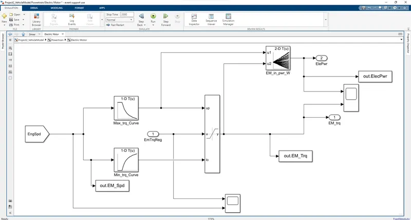
- Based on engine speed, the required EM torque is saturated by the controller between maximum EM torque and maximum EM torque.
Curve and maximum EM torque generation curve and EM torque are transmitted to the crank hub. - A 2D lookup table is used to calculate the motor electrical input power based on the EM speed and EM torque.
3. Crank Hub:
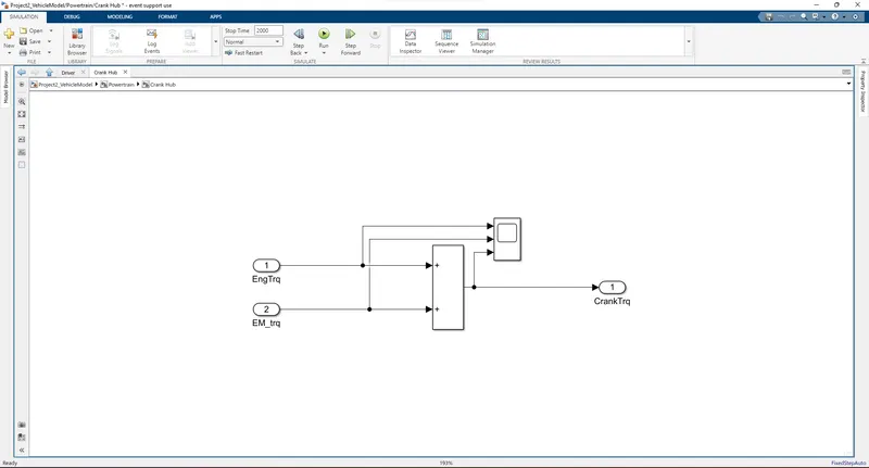
- The crank hub adds the EM torque and the motor torque and sends it to the gear block as a crank torque.
4. Transmission:
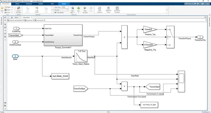
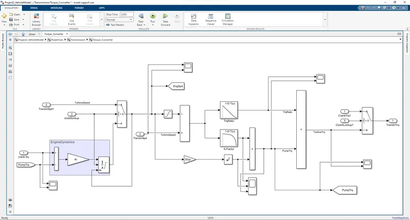
- The Engine block has connected through the transmission block it has automatic transmission system were it has torque convertor. it convert the engine power into torque in the vehicle movement stage
- In this block, the transmission-controlled gear selection is multiplied by the engine torque and the torque converter efficiency and engine dynamics are transferred to this model.
- Torque Convertor:
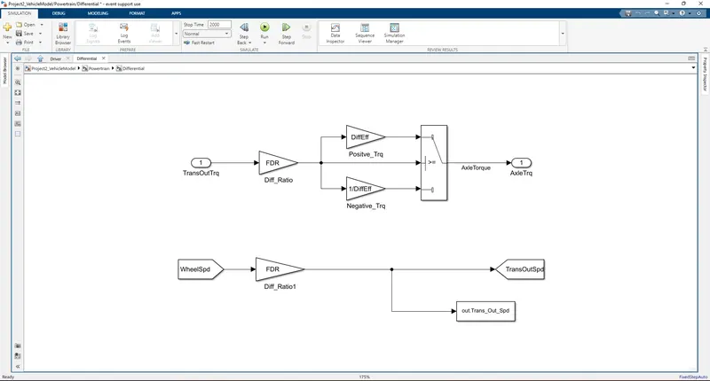
5. Differential:
- In this block, the transmission output torque is multiplied by the differential ratio and the differential efficiency, and the resulting torque is transmitted to the wheels as axle torque.
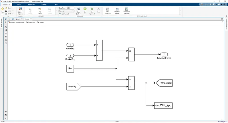
6. Wheels
- The brake torque from the control model is subtracted from the axle torque and divided by the turning radius to determine tractive force.
- Wheel speed is calculated from vehicle speed and saved in workspace.
7. Vehicle Dynamics:
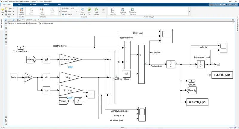
- The "Vehicle Dynamics" block shows the longitudinal dynamics of the vehicle along with the road load
- Tractive Force and Road loads are used to calculate the vehicle velocity
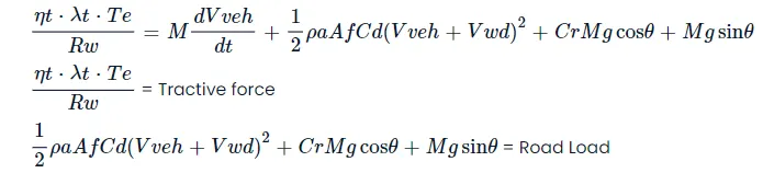
- Where
ρ a - Air Density
A f - Frontal Ares
C d - Drag Coefficient
C r - Rolling Coefficient
M - Mass of Vehicle
g - Acceleration due to gravity
θ - Slope
- Then file were created successfully and then run the file
- Variables are loaded into the workspace using a MATLAB script.
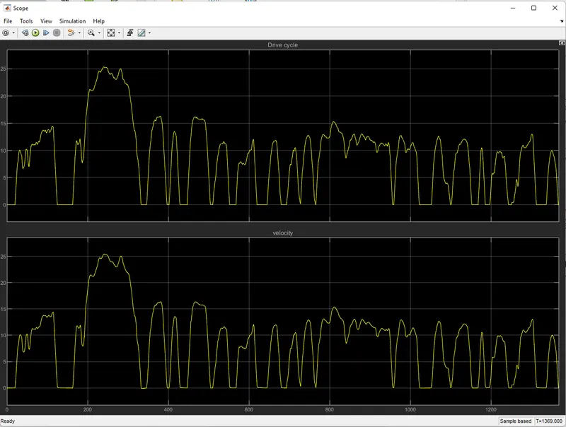
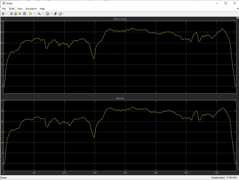
- Acceleration, velocity and distance traveled are calculated and saved in the workspace.
- Simulation Result:
- USSD Cycle:
- HWFET Cycle:
- Post-Processing:
Another file were created and given named as 'Project2_FinalFile.m',it has do some basic post process for the evalute the model and some of ouput were created and show in form of the graph
- Results:
(a). Tabulate the fuel economy numbers (kmpl) for UDDS and HWFET cycle. Compare these numbers with the baseline numbers for conventional vehicle model from Project 1.
- USSD Fuel Economy:
- For Conventional Vehicle Model:

- For P1 Hybrid Vehicle Model:

- In USSD Cycle Fuel Economy has improve were compare to Conventional Vehicle Model because of eleminate Negative torque and negative power
- negative power were revived by regen braking
- HWFET Cycle:
- For Conventional Vehicle Model:

- For P1 Hybrid Vehicle Model:
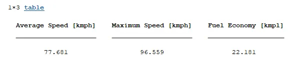
- The fuel consumption is improved because the negative power of highway driving is small. But all negative power is recuperated by regenerative braking, increasing his SOC of the battery.
- Fuel consumption in urban areas is much lower than highway driving due to reduced brake pad engagement and drive cycle idle time.
(b) Plot the time trace for engine, transmission input, transmission output and wheel speed on one plot.
- USSD:
- HWFET:
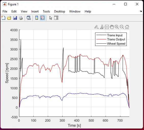
- Much of the fluctuating input speed is dampened by the torque converter, and the transmission input speed changes according to the engine torque required to complete the drive cycle.
- Wheel speed and transmission output speed depend on gear and differential ratio.
(c) Plot engine torque, engine power, fuel rate and fuel consumption using subplots.
- USSD:
- HWFET:
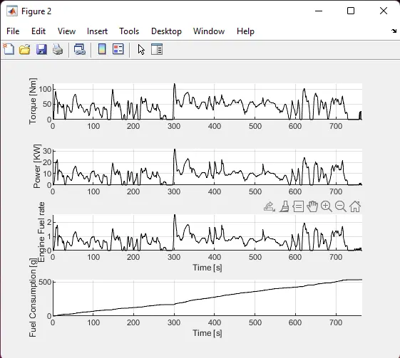
- Due to the different torque requirements of the drive cycle, the fuel flow changes and fuel consumption is calculated.
- HWFET drive cycles have higher power and torque requirements and less negative torque and power.
(d) Plot accelerator and brake pedal, gear command, vehicle desired and actual speed, vehicle distance using subplots.
- USSD:
- HWFET:
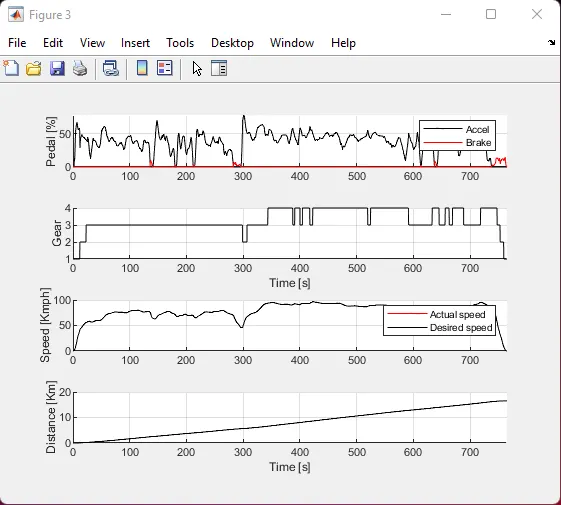
- Braking is less demanding, highway drive cycles use more of the accelerator pedal, and gear changes are more frequent because the drive cycle is smoother.
- Accelerator and brake pedals, gear command from transmission control unit, vehicle target speed, actual vehicle speed, and actual vehicle distance are plotted
(e) Plot the engine operating points on the engine fuel map.
- USSD:
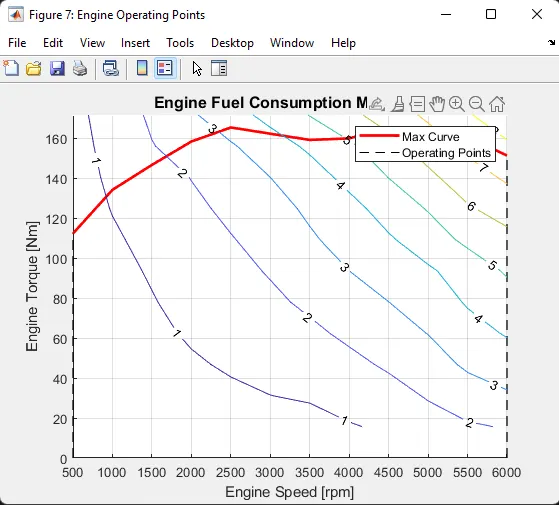
- The engine operating point is plotted on the fuel map and the operating point is below the maximum torque curve.
(f) Plot motor speed, torque, motor input power using subplots
- USSD:
- HWFET:
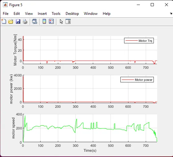
- If the vehicle is moving fast and idling less on the highway, the torque requirement for the EM motor will be lower.
(g) Plot pack voltage, current and SoC using subplots.
- USSD:
- HWFET:
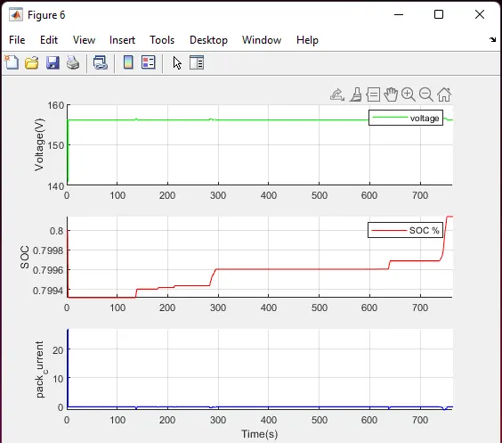
- The battery increased with highway driving cycles. This is due to e-motor usage and reduced battery charging during braking in this area.
(h) Plot the motor operating points on the motor input power map, with the motor max motoring and generating torque curves.
- USSD:
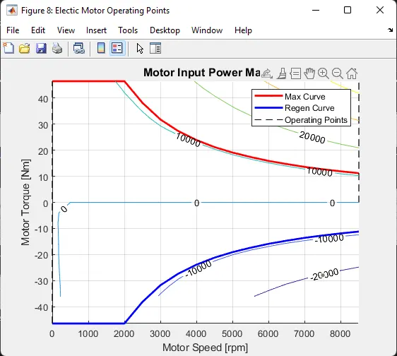
- Electric motor can operates among max motoring torque curve and max producing torque curve.
Conclusion:
- Analyze and understand vehicle Models operating point based on engine speed, torque, transmission speed, pedal position, gear and mileage.
- Analyze and plot various characteristics of UDDS drive cycle and HWFET drive cycle characteristics and operating points.
- Post-processing calculations have been performed and the required figures have been drawn successfully.
- Time curves of engine, transmission input, transmission output and wheel speed over time.
- Engine torque, engine power, fuel rate, and fuel consumption over time.
- Accelerator and brake pedals, desired gear and desired vehicle, actual speed and vehicle distance.
- Engine operating point on engine fuel map against timeEngine speed, torque and engine input power versus time.
- Pack voltage, current, and state of charge over time. The engine operating point on the engine input power map against time.
It is also compared with HWFET drive cycles and their counts.
Files:
- The Model Uploaded in the name of 'Projrct2_vehicleModel.slx' and also pre and post processing files also uploaded in the name of 'Project2_InitFile.m' and 'Project2_FinalFile.m'
- The Output file also uploaded in the image formate in the answer body
- Then Drive cycle file also uploaded in named as "UDDS.mat" and "HWFET.mat"