Wiring harness design in CATIA V5 - 3D modeling Week 2 Challenge
Q1] Download following connectors & Connector clip cad data from given link & define it as Electrical Connector using Electrical Part design Workbench. Define all the necessary properties to Connectors & Clip.
- Deutsch DT06 – 08SA ( https://www.te.com/usa-en/product-DT06-08SA.html)
- Tyco 174357-2 (https://www.te.com/usa-en/product-2-174357-2.html?source=header-match)
- Tyco 85229-1 – (https://www.te.com/usa-en/product-85229-1.html?q=85229&source=header)
Answer
- Connecctor1 (Deutsch DT06 – 08SA):
- First download stp File were given in the question Then load file in Catia V5
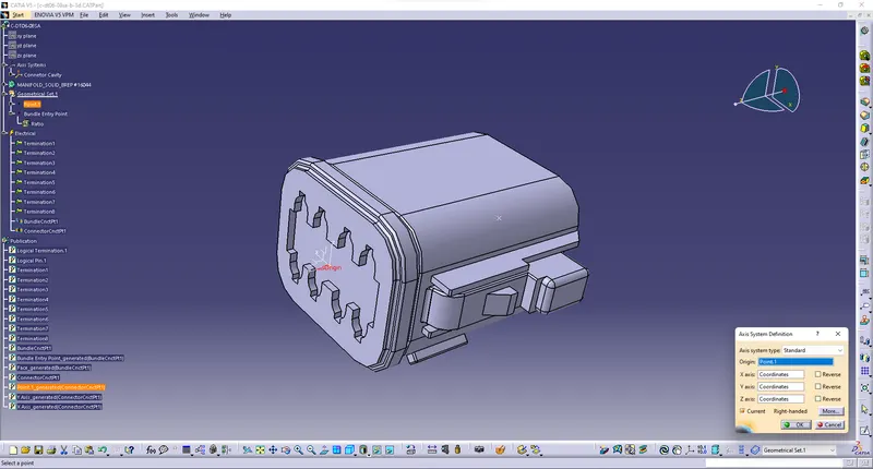
- Let assign the geometric parameter in the Deutch DT06-08SA Connector by selecting the axis option from the Part Design
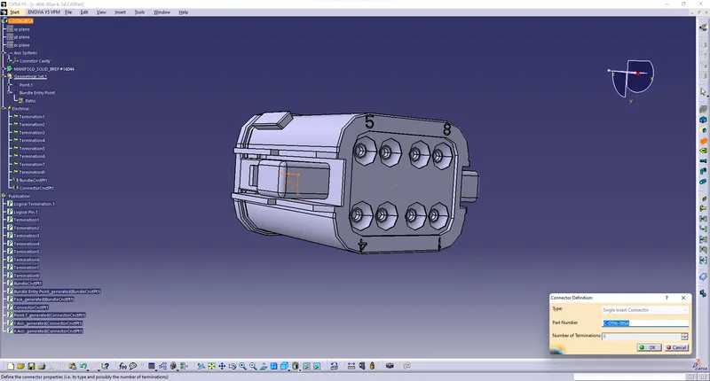
- Then Switch Part Design to Electrical Part design for Define the part as connector for the given connector
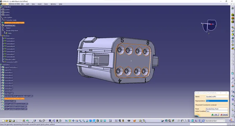
- And Define the Bundle Connector point by seleccting the Bundle connector option
- Again define the Connector connection point by selecting the Connector Connection option
- Those Images were mention below in the step by steps
- Step 1: Assign geometric parameters in parts
- Step 2: Define Part as connector
- Step 3: Define Bundle Connection Point
- Step 4: Define Connector Connection Point
- Connector2 (Tyco 174357-2):
- First download stp File were given in the question Then load file in Catia V5
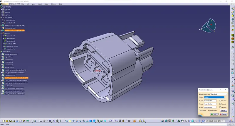
- Let assign the geometric parameter in the Tyco 174357-2 Connector by selecting the axis option from the Part Design
- Then Switch Part Design to Electrical Part design for Define the part as connector for the given connector
- And Define the Bundle Connector point by seleccting the Bundle connector option
- Again define the Connector connection point by selecting the Connector Connection option
- Then Define Cavity Connection Point By selecting Cavity Connection option
- Those Images were mention below in the step by steps
- Step 1: Define Geometric Parameter
- Step 2: Define Part as Connector
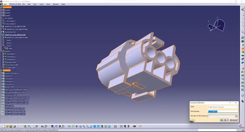
- Step 3: Define Bundle Connection point
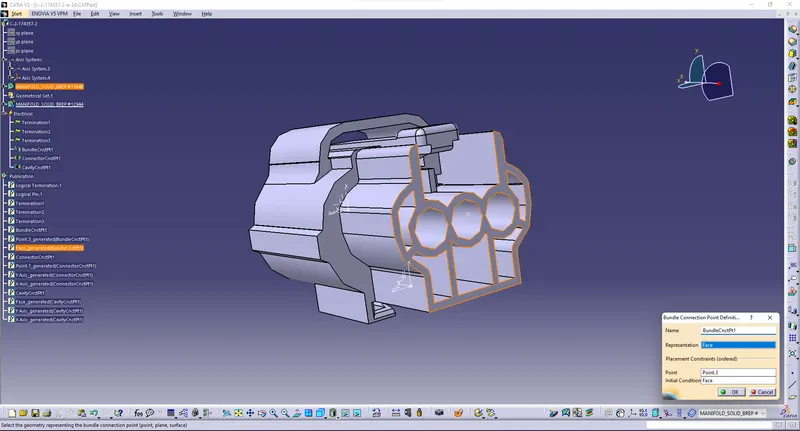
- Step 4: Define Connector Connection Point
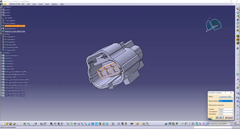
- Step 5: Define Cavity Connection Point
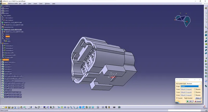
- Clip & Connector2 (Tyco 85229-1):
- First download stp File were given in the question Then load file in Catia V5
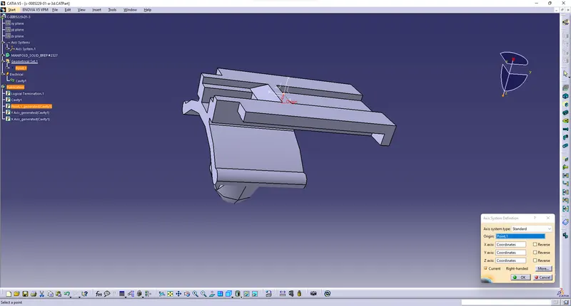
- Let assign the geometric parameter in the Tyco 85229-1 Connector by selecting the axis option from the Part Design
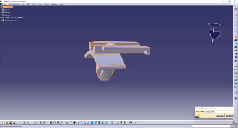
- Then Switch Part Design to Electrical Part design for Define the Mounting Equipment as Clip for the given connector
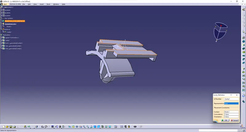
- Define the Cavity by seleccting the Cavity connection option
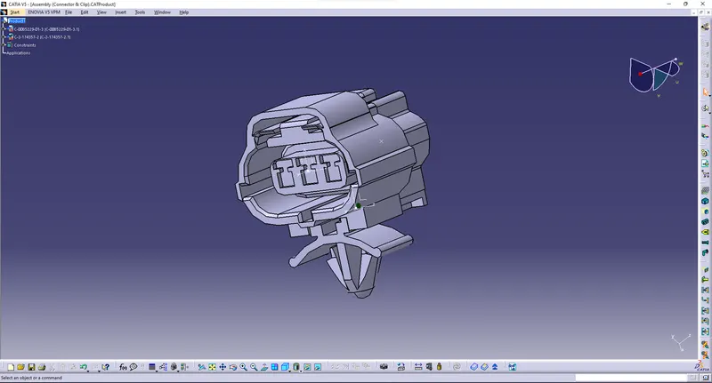
- Then swicth Electrical Part Design to Electrical Assembly Design for the assembly of clip and connector
- It will open new window and copy the both file and place it and choose Connect Electrical device
- Those Images were mention below in the step by steps
- Step 1: Define geometric parameter
- Step 2: Define Mounting Equipment
- Step 3: Define Cavity connection point
- Step 4: Assembly of clip and connector by using connect Electrical Devices
- Files:
- All Files were uploaded in the zip file format and named as Week 2 Challenges.zip and images also uploaded in the same Zip file