Design of backdoor
DESIGN OF BACKDOOR
Objective
To design the backdoor or tailgate of the car using siemens NX cad.
Introduction
Tailgate or back door of the car is used to load the luggages or accomodate the passanger at rear seats.
Types of Backdoor
- Top Mounted
- Bottom Mounted
- Side Mounted
There are different components that are assembled with backdoor. In this design the following things are to be modelled.
- Inner panel
- Outer panel - upper
- Outer panel - lower
- Latch and striker Reinforcement with trajectory
- Hinge Reinforcement
- Gas stay reinforcement
- Wiper motor reinforcement
- Windshield reinforcement
- Force Distribution
- Mastic Points
Methodology
1. Top Down assembly modeling
Top-down assembly modeling is an assembly-centric modeling method where the assembly design is started at the highest level possible, and individual parts and subassemblies are defined within the context of the overall assembly. With this approach, an assembly layout is typically created first, and this assembly layout is used to define individual part geometry and position.
This approach is often used at companies where the product being designed is large enough that it requires many people to complete the design. A senior-level designer might create the initial assembly layout, then divide the assembly layout into logical subassemblies and parts for the remainder of the organization to complete.
2. Bottom up assembly modelling
Bottom-up assembly modeling is a part-centric modeling method where the assembly design is started with a principal structural or functional element, and individual parts are designed in relative isolation from the overall assembly. Component parts and subassemblies are defined as the process moves up towards the top-level assembly. With this approach, as the design of a key component is completed, its geometry may or may not be used to aid the design of related mating components.
This approach is often used at companies where the product being designed is small enough that one or only a few people are needed to complete the design.
3. Combined Approach
Solid Edge provides tools that allow you to take advantage of the benefits of both approaches as needed. Many organizations use a combination of both methods, using the method which best suits the immediate requirements. For example, you can use the top-down approach to create the initial assembly layout and to define the document structure needed. You can then copy the assembly layout geometry to subassembly and part documents to divide the work among the organization.
Here the top down assembly modelling is used to design the backdoor.
Components
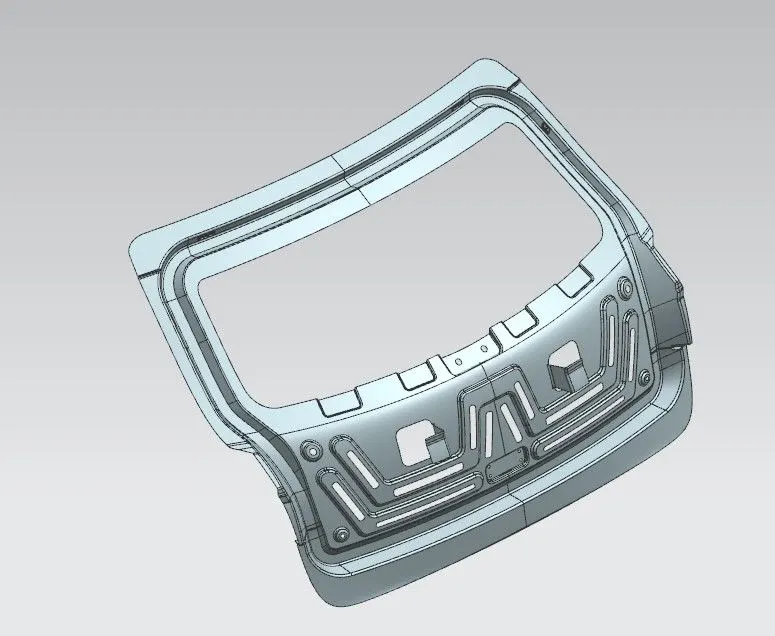
1. Inner Panel
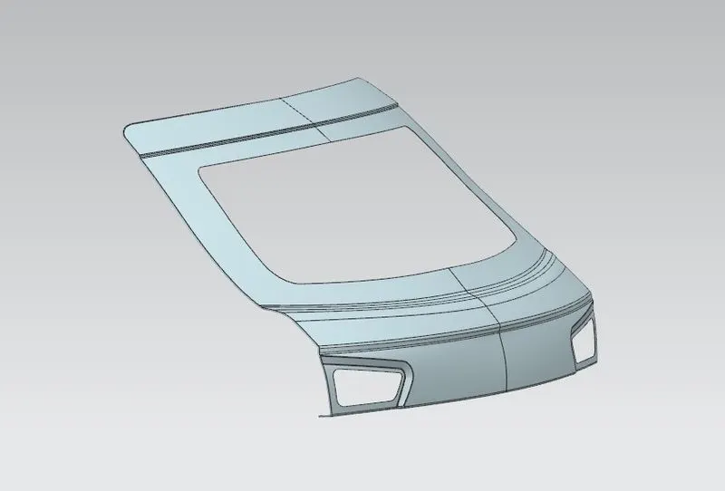
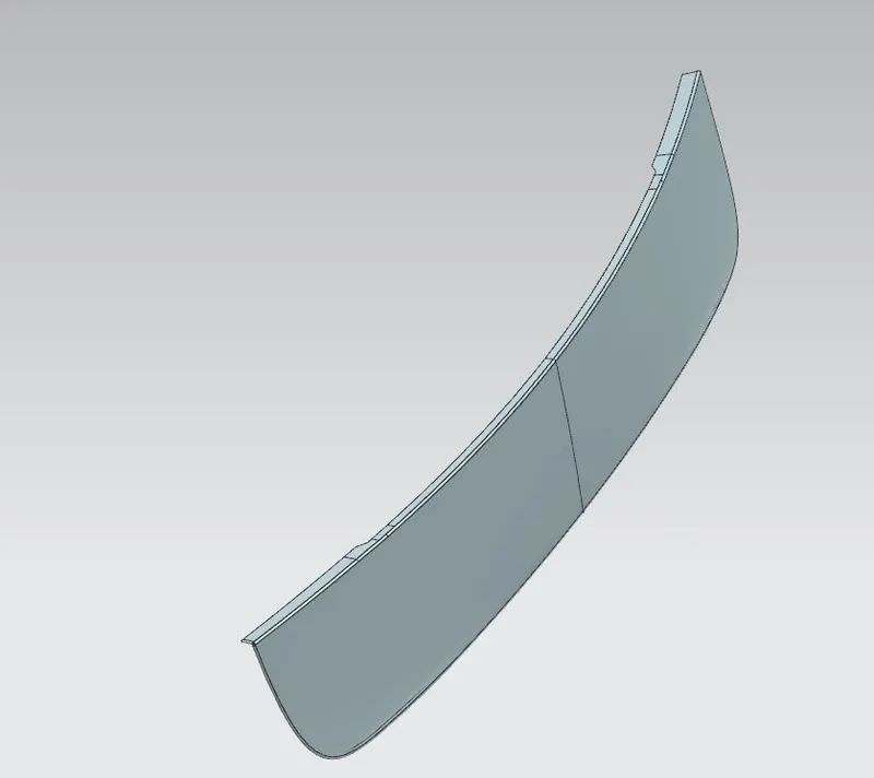
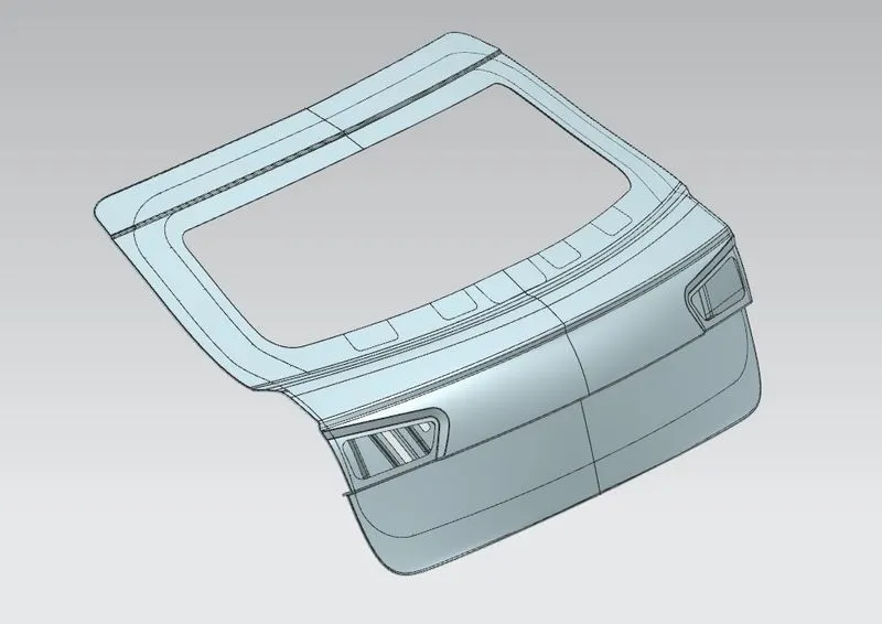
Car tailgate or backdoor consists of three different panels that are assembled together. They are Inner Panel, Outer pael upper and lower.
2. Outer panel - Upper
3. Outer Panel - Lower
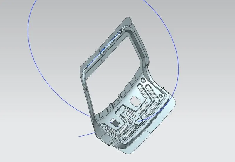
4. Latch and striker reinforcement with trajectory
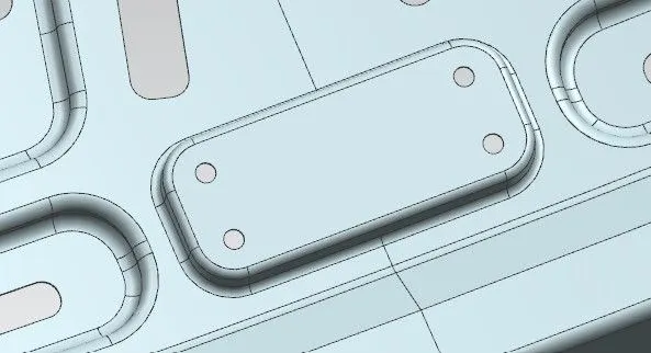
At the front of the vehicle, a safety latch retains the backdoor. Locating and releasing the safety latch releases its hold on the hood and then the hood is allowed to open.
Latch Trajectory
It is the trajectory of the car hood in the car when opening and closing.
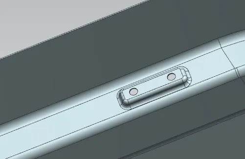
5. Hinge Reinforcement
The active hinge must lift up the backdoor in appropriate short time to extend the deformation space between the backdoor and the rigid parts.
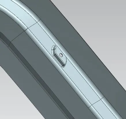
6. Gas stay reinforcement
Gas stay reinforcement is used to fit the one end of gas stay with door.
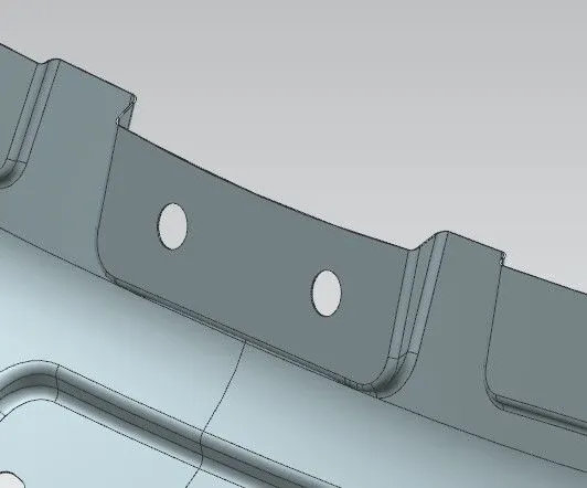
7. Wiper motor Reinforcement
Wiper motor reinforcement is used to accomodate the wiper motor
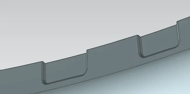
8. Windshield Reinforcement
9. Force Distribution
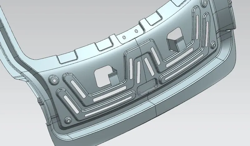
In case of Impact or crash, the transmission of impact force through the backdoor is controlled by designing the backdoor inorder to minimize the force which reaches passenger.
10. Mastic Points
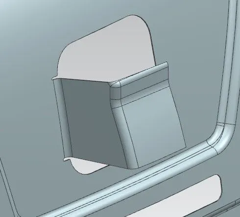
Mastic sealant can be used to either join one surface to another, or protect the area to which it is applied (cars and boats). And because it stays flexible even after it cured, it is ideal for projects requiring the joined materials (surfaces) to have some movement (glass balustrades, building joints). It works particularly well with include wood, glass, aluminium, concrete, marble, steel, and duct board. Industrial uses for this adhesive include repairing duct work in the heating and air industry. This is due to its heat resistant properties and the ability to seal and form and a strong bond, applied using a mastic sealant gun (caulking gun).
Other Applications Of Mastic
- It is for holding load-bearing walls in place.
- It is for ceiling projects, especially to eliminate the need for drywall support as it sets and dries quickly.
- It is for holding materials temporarily so the materials can be fasted, fixed, or attached by a single person working.
Hemming
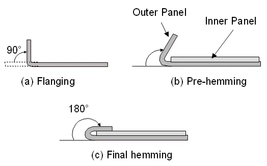
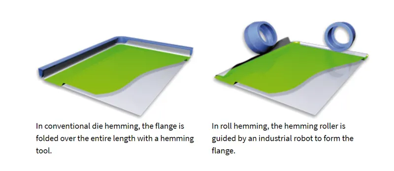
- Hemming is a forming operation in which the edges of the sheet are folded or folded over another part in order to achieve a tight fit. Normally hemming operations are used to connect parts together, to improve the appearance of a part and to reinforce part edges.
- In car part production, hemming is used in assembly as a secondary operation after deep drawing, trimming and flanging operations to join two sheet metal parts (outer and inner) together. Typical parts for this type of assembly are hoods, doors, trunk lids and fenders.
- The accuracy of the hemming operation is very important since it affects the appearance of the surface and surface quality. Material deformations, which occur during the hemming process, can lead to dimensional variations and other defects in parts. Typical hemming defects are splits or wrinkles in the flange, material overlaps in the corner areas or material roll-in. This is why it is important to use simulation tools in order to, on the one hand, better understand the hemming process and, on the other hand, significantly reduce the number of “trial and error” loops during tryout und production.
There are various types of hemming operations:
- Conventional die hemming
- Roll hemming
Backdoor Assembly
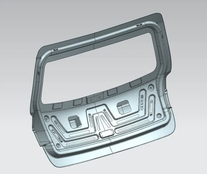
Feature Definitions
1. Extract Geometry - to create an associative or non-associative body, point, curve, or datum by extracting from existing objects.
2. Trim Body - to trim one or more target bodies using a face or plane.
3. Offset curve in face - to create offset curves on one or more faces from connected edges or curves on the surfaces. The offset curves can be associative.
4. Law Extension - to extend an existing surface or sheet based on the laws for distance and the angle of the extension.
5. Offset Surface - to create an offset of one or more existing faces.
6. Trim Sheet - to trim sheet bodies to intersecting faces and datums, and projected curves and edges.
7. Face Blend - to add tangent and curvature continuous blend faces between two or three sets of faces.
8. Projected Curve - to project curves, edges, and points onto faces, faceted bodies, and datum planes.
9. Mirror Geometry - to create associative or non-associative mirrored geometry about a specified plane.
10. Sew - to join two or more sheet bodies into a new single sheet body. If the collection of sheet bodies encloses a volume, a solid body is created.
11. Thicken - to offset one or more connected faces or sheets into a solid body.
12. Datum Coorninate System - to quickly create a coordinate system consisting of a set of reference objects.
13. Through Curves - to create a body through multiple sections where the shape changes to pass through each section.
14. Trim and Extend - This option lets you extend and trim one or more surfaces using a set of tool objects composed of edges or surfaces.
15. Edge Blend - to round sharp edges between faces.
16. Emboss - Modifies a body with faces made by projecting a section along a vector. Emboss features are useful for stiffener and locator objects.
17. Datum Plane - to create a planar reference feature to help define other features, such as swept bodies and features at angles to the faces of target solids. Datum planes can be associative or non- associative.
18. Wave Geometry Linker - to copy geometry from other parts in the assembly into the work part.
19. Extend Sheet - to extend or trim a solid or sheet body.
20. Sweep - Creates a solid body or sheet body by sweeping a curve outline through a path in space along one, two, or three guide strings. Swept is well suited for sweeping to create a feature if your guide strings consist of splines or a helix.
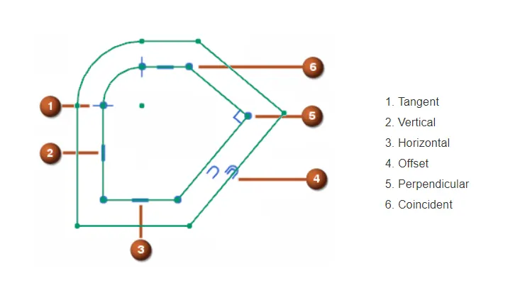
21. Geometric Constrains
Geometric Constraints Specify and maintain geometric conditions for or between sketch geometry.
For example, geometric constraints can establish:
-
A line as vertical or horizontal.
-
Two lines as perpendicular or parallel to each other.
22. Assembly Constrains
Use the Assembly Constraints command to define positions of components in the assembly. NX uses directionless positioning constraints, which means that either component can move to solve the constraint.
You can use assembly constraints to:
-
Constrain components so they touch each other or align with each other. The Touch Align constraint is the most commonly-used constraint.
-
Specify that a component is fixed in place. This is useful when you want to control which components move when the software solves a constraint.
-
Bond two or more components together, so they move together.
-
Define a minimum distance between selected objects in components.
Conclusion
Thus the backdoor or tailgate of the car is designed by siemens NX cad as per the requirements and results are obtained and uploaded.