Design of backdoor
BACK DOOR DEFINITION:
Rear door means a door or door system on the back end of a motor vehicle (e.g. a rear hatchback or tailgate) through which passengers can enter or depart the vehicle or cargo can be loaded or unloaded.
TYPES OF DOOR OPENING:
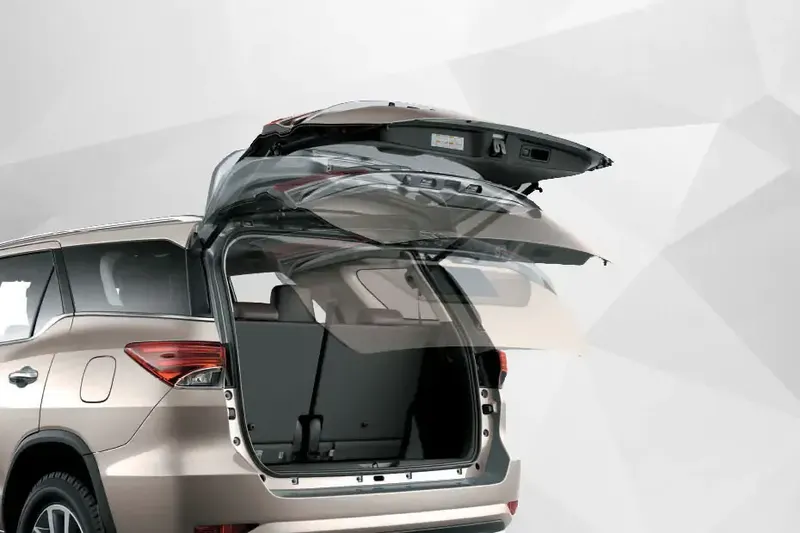
- Top mounted door
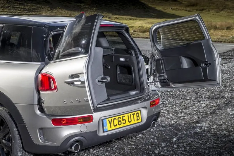
- Side mounted door
- Bottom Door
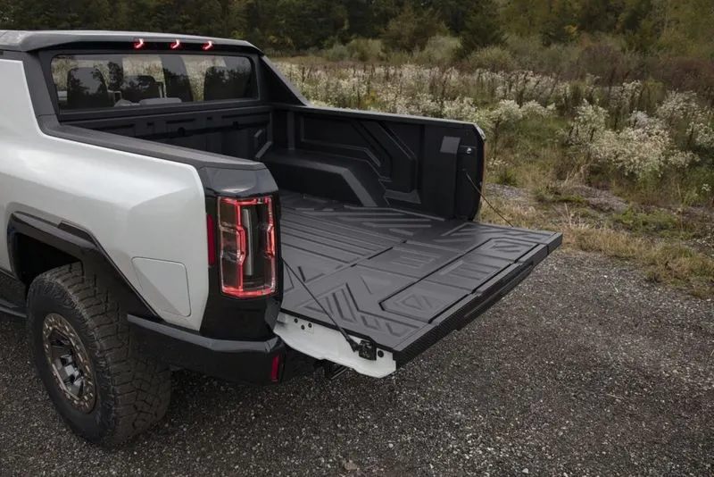
In these project, I designed Top mounted door,So here we discuss mainly about top mounted door only.
Sheetmetal operations are done in the Back Door:
Deep Drawing:
The metal deep drawing process is an effective method of manufacturing of cups, cans and other similar deep drawing products. The deep drawings having two main categories.
- First- stage drawing: The blank shape of metal is placed on the die and contact with the punch. When the metal specimen is flat piece of sheet metal used in forming and finish the product. Initially the punch moves in downward direction. The outer rim of blank is subjected to pure radial drawing (drawing toward in vertical axes) between die and blank metal. The metal become a bend and sliding over die and also stretched between die and punch. The metal in vicinity of punch head and contact with it bend and slide over radii and stretch over punch head.
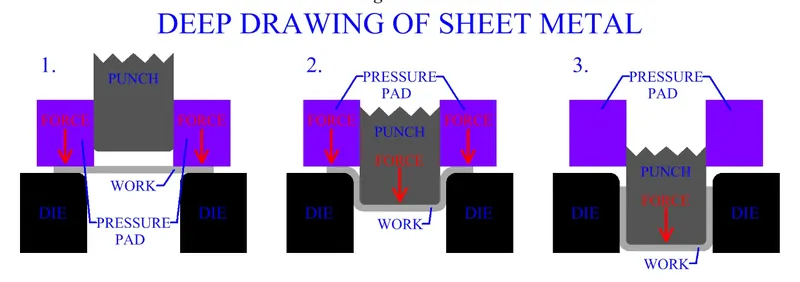
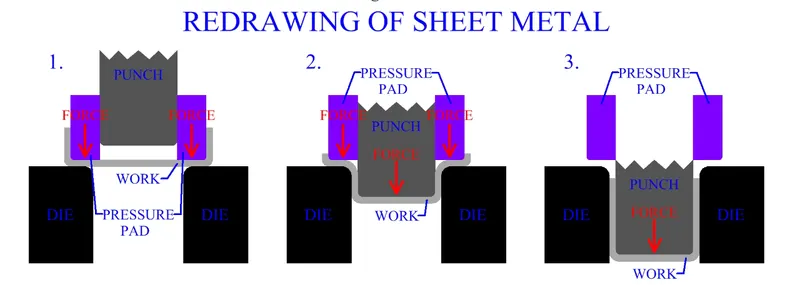
2.Redrawing: The components drawn from first stage again it is redrawn convert into more depth to form a cup shape in the die and punch. The second stage of drawing is called as redrawing.
Embossing:
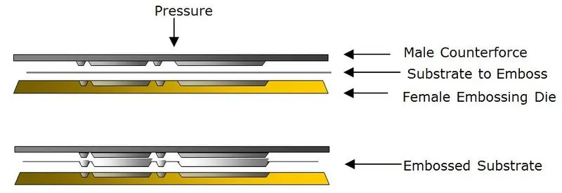
Embossing is a metal forming process for producing raised or sunken designs or relief in sheet materials by means of matched male and female roller dies, theoretically with no change in metal thickness or by-passing sheet or a strip of metal between rolls of the desired pattern. Metal sheet is drawn through the male and female roller dies producing a pattern or design on the metal sheet. Depending on the roller dies used, different patterns can be produced on the metal sheet.
Materials commonly used in the metal embossing process include:
- Aluminum (All Alloys)
- Aluminum (T1/T2)
- Brass
- Cold rolled steel
- Copper
- Galvanized steel
- High strength, low alloy, steel
- Hot rolled steel
- Steel (All Alloys)
- Zinc
Hemming:
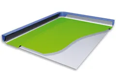
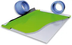
Hemming is a forming operation in which the edges of the sheet are folded or folded over another part in order to achieve a tight fit. Normally hemming operations are used to connect parts together, to improve the appearance of a part and to reinforce part edges.
In car part production, hemming is used in assembly as a secondary operation after deep drawing, trimming and flanging operations to join two sheet metal parts (outer and inner) together. Typical parts for this type of assembly are hoods, doors, trunk lids and fenders.
There are various types of hemming operations:
- Conventional die hemming: In conventional die hemming, the flange is folded over the entire length with a hemming tool.
- Roll hemming: In roll hemming, the hemming roller is guided by an industrial robot to form the flange.
Design Considerations for a Back Door:
- Rear Visibility for Functionality and Safety.
- Boot Space and Accessibility.
- Type of Backdoor Opening (For individual vehicle requirement).
- Fixing and Support Structures like Hinges and Gas stays.
- Mounts for Wiper Motor, Back Lights/Tail Lamps and Other Wiring loops.
- Fit and Clearance (For Assembly and Aesthetically looks).
- Strength Of Backdoor (Require in collision).
Components to create:
- Outer Upper Panel.
- Outer Lower Panel.
- Inner Panel.
- Gas Stay Reinforcement LH And RH.
- Hinge Reinforcement LH and RH.
- Striker Reinforcement.
- Wiper Reinforcement.
Develop a detailed report for the Back door design by explaining the design methodologies and about the components developed in the design:
Inputs for designing of backdoor:
- Outer Panel - 0.75 mm
- Inner Panel - 0.75 mm
- Reinforcements - 1.5 mm
SEW AND FIX VARIOUS SURFACE IRREGULARITY:
- In case found dis joined unable sew
- Hide the surface create the bridge curve tangent
- Then create surface then perform sew operation
- In case any irregular trim the sheet using off set curve in face
- Then repeat bridge curve and through curve opertion
- Near rear lamp outer area remove irregular surface then apply face blend
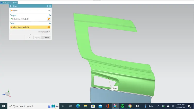
- In corner irregular face blend found elimate by using corner blend to improve surface look
- Minimum 8mm require the spot weld both inner and outer panel
- Extract lower flange from upper outer panel using extract geomentry
- Expanding surface 10mm at lower suface flange
- Further face blend applyed at lower outer panel to flange
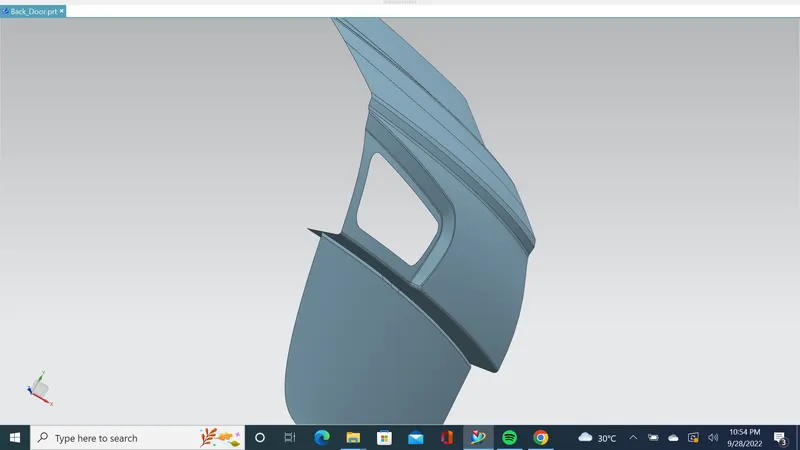
- Extract both upper and lower panel of outer back door
- Save it seperately
TOP TO DOWN APPROACH CREATING ASSEMBLY
- Creating inner panel design
- Using wave geomentry copy work part into the back door inner panel
- Hide other assembly parts
- Adding links of upper and lower panel into feature group
- Creating tooling direction based upon deep drawing manufacture process
- Creating a sealing flange because of avoiding water flow into the luggage rack
- Sealing flange 25mm during open & 15mm compressed after closed the back door
- Not going to work on parent surface so extract geomentry
- For thickening 0.75 for hemming consider bothside 0.75x0.75+0.2 (0.2 is mastic)
- Offseting surface both upper and lower panel down ward direction (0.75x2+0.2)
- Hiding other surfaces
- Again offset require flange 25 mm
- Offset curve on face 60mm from 60mm do offset curve on face 30mm (Here instead of 25mm to 30 considering fillet cut)
- Offset curve on face 145mm, 40mm from 30mm & 70mm
- Trim sheet
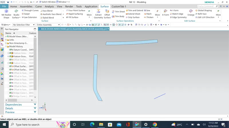
- Bridge curve & through curve mesh
- Off set surface light area up to 80mm then untrim the surface
- Off set curve in face then trim down
- Again bridge curve and through curve mesh
- Off set lower panel & draw a sketch require flange shape
- Then trip it down and by using bridge connect both and lower flange
- Generate surface between them using through curve mesh
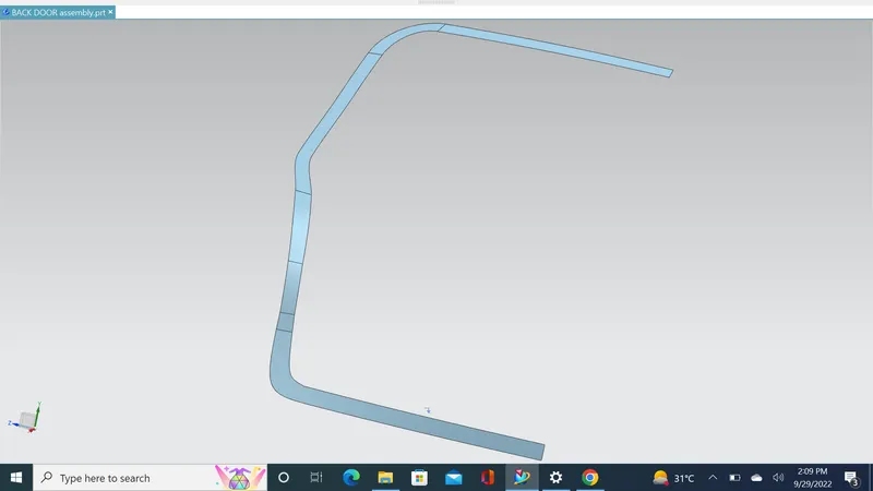
- Law of extension outer side with drafting angle of 10mm
- Face blend & extract geomentry
- Checking surface by applying thicken command
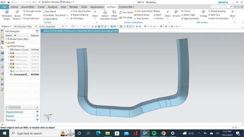
Creating connecting flange:
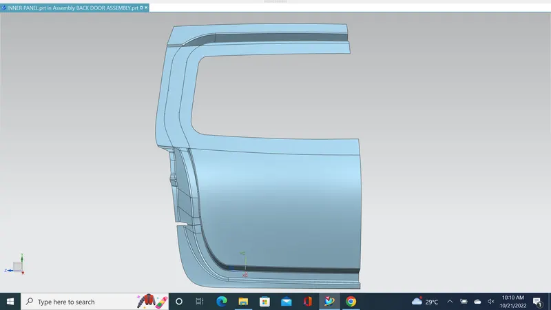
Tooling Direction:
A tooling direction was set for the deep drawing operation as shown in the figure. It is desirable in drawing operations to maximize material flow in the plane of the sheet and to minimize the material flow in a direction perpendicular to the plane of the sheet.
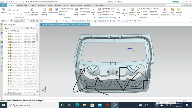
Force Dissipation:
The major criteria in designing the back door or any BIW part is the force dissipation during an impact or a colloision. Hence studies are being done inorder to dissipate the force on the sides and avoiding it reach the inner cabin of the car so that possible damage of imapct inside the car is reduced. Hence inorder to do that the V or Y embosses are created on the inner panel so that the force gets transmitted on to the sides instead reaching it on the cabin. This is one of the main criterias in back door design.
Mastic Flange:
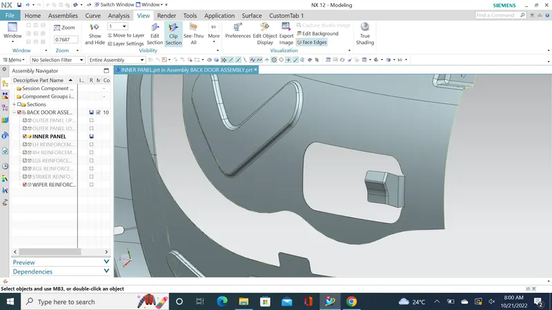
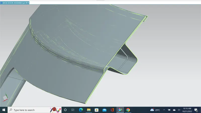
This mastic flange is created by punching the inner panel during manufacturing. One important consideration that should be accounted is the corner relief to prevent stress concentration at the corners.
Outer Panel
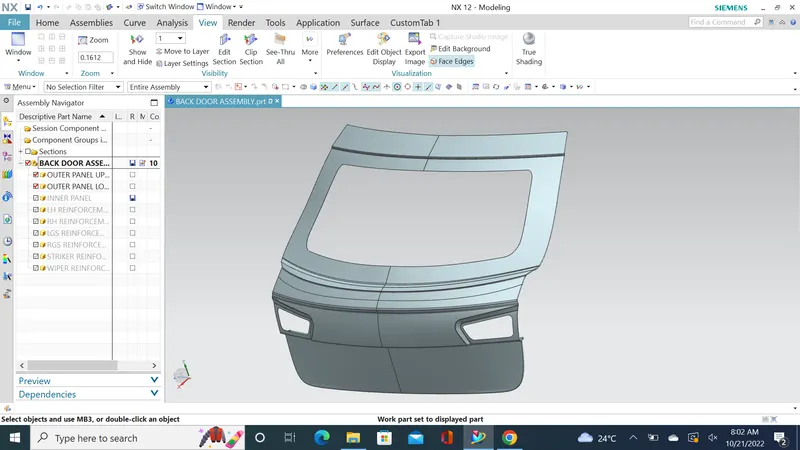
As the name suggests, it is the outer part of the rear door and is mostly responsible for aesthetics of the vehicle. Outer and inner panels are connected by mastic sealants in center and by hemming process at edges. The outer door handle and in some cases, the number plate may also be installed on the outer panel of the back door. We have considered a 2-part outer panel for our design, outer upper panel and outer lower panel prospectively. Outer panel is manufacture by stamping sheet metal. Thickness for outer panel is 0.75 mm.
Gas Stay Reinforcement:
Gas Stay is a device used to support the back door in its open position. Gas stay requires no manpower & it is engaged into support position automatically as the back door opens. One end of the Gas Stay is fixed on the backdoor & another end is on the Body Side or on the Back door stationary area.
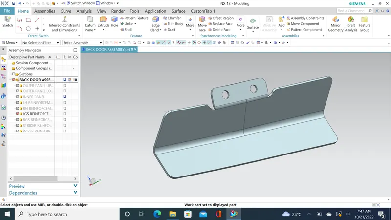
Embossing is provided at the Gas Stay mounting area to compensate for weakness & improve strength.
WIPER MOTOR REINFORCEMENT:
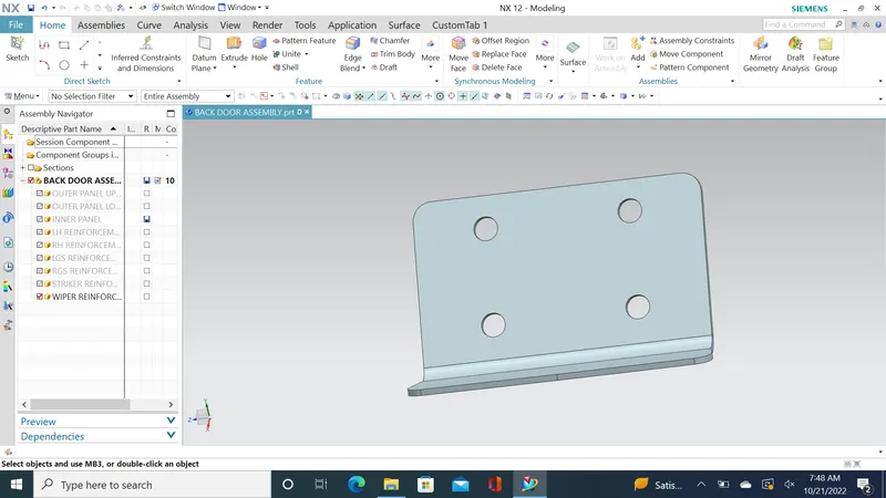
Wiper is used to to wipeout the rain water falls on the backdoor window.It is actuated by the motor which is mounted on the inner panel.Due to the vibration and heat created by the motor .the inner panel where the motor is mounted gets deform and the parts attached to the motor starts to vibrate which leads to poor NVH.So we have to provide the reinforcement where the wiper motor is placed.
LATCH REINFORCEMENT:
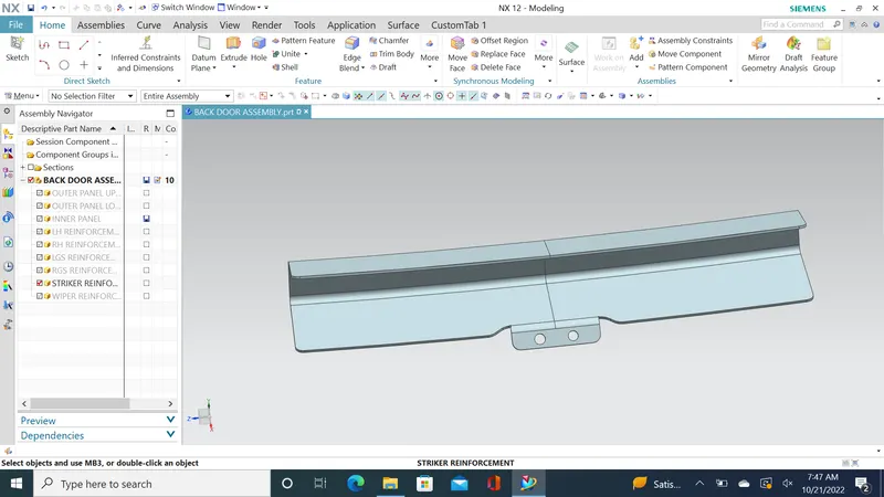
At bottom of the panel , reinforcement and emboss are given to accomodate the latch and striker assembly.Generally key operated or automatic remotly controllable mechanism is used to keep the door open or closed.The actuators , recivers and other electronic devices are mounted on the inner panel only.
CORNER RELIEF:
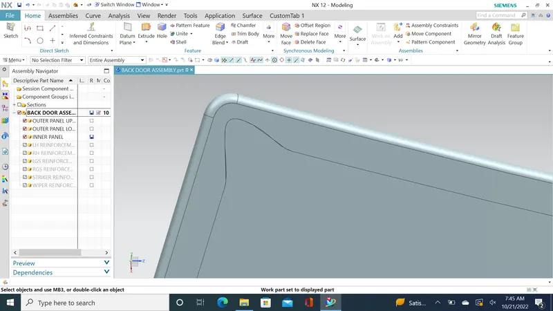
During the hemming process, when giving the Corner Relief helps to control sheet metal material behavior & to prevent unwanted deformation during unbend operations & also helps to minimize the number of passes in hemming.
Latch and Stricker Positions:
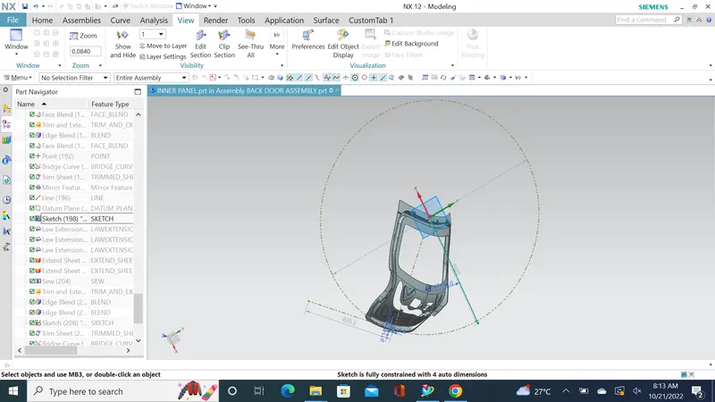
The Latch and Stricker positions play a major role in determing the opening and closing of the back door. Hence the opening and closing of the had to smooth and inorder to ensure that the the centre point of the latch and stricker has to to be at the same point and the trajectory has to be tangent to the open close circle that is drawn. This is shown in the below image. Only if the centre points and the tangent line are perfect the opening and closing of the back door is smooth and clear. Or else the Hinge positions, Gas stay positions and Latch and Stricker Positions has to be altered to meet the change.
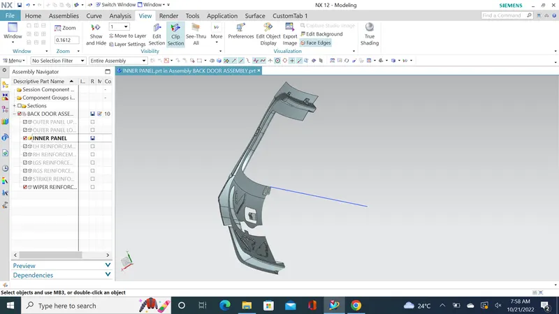
CLIP SECTION VIEW:
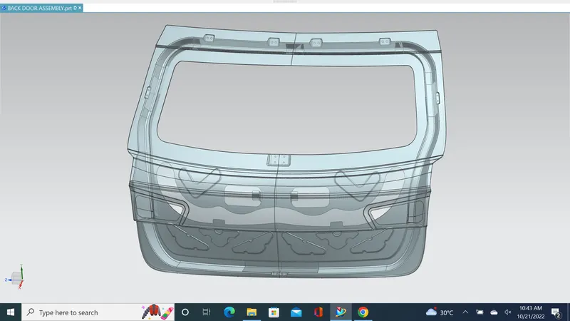
AFTER ASSEMBLY:
DRAFT ANALYSIS:
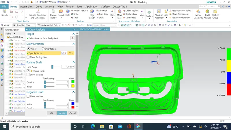
- The draft analysis was performed for the tooling direction created at first and checked that the model is suitable for manufacturing.
- Then to get a complete green portion the required changes to the draft angle of the embosses were carried out by optimizing the model.
- The Draft Analysis command is used to detect that the part drafted will be easily removed or not.
- This type of draft analysis is performed based on color ranges.
- The identifying zones on the analyzed element where the deviation from the draft direction at any point, corresponds to specified values.
CONCLUSION
- The back door outer and inner panel were designed with the help of the styling surface along the tooling direction.
- Draft analysis was performed on the inner panel and it was concluded that the component can be easily manufactured along the tooling direction.
- All the reinforcements were designed and placed at appropriate positions to provide strength at critical regions.