Design of backdoor
DESIGN OF CAR BACKDOOR WITH NECESSARY REINFORCEMENTS
Aim:
To design the complete back door assembly along with reinforcements of the car from the provided class A surface using proper design methologies.
Introduction:
The trunk or boot of a car is the vehicle's main storage or cargo compartment, often a hatch at the rear of the vehicle. It is also called a tailgate. The door or opening of a cargo area may be hinged at the top, side, or bottom. The trunk or luggage compartment is most often at the rear of the vehicle. These doors can be either operated manually or electric powered. In most of the luxury cars door is electrically operated.
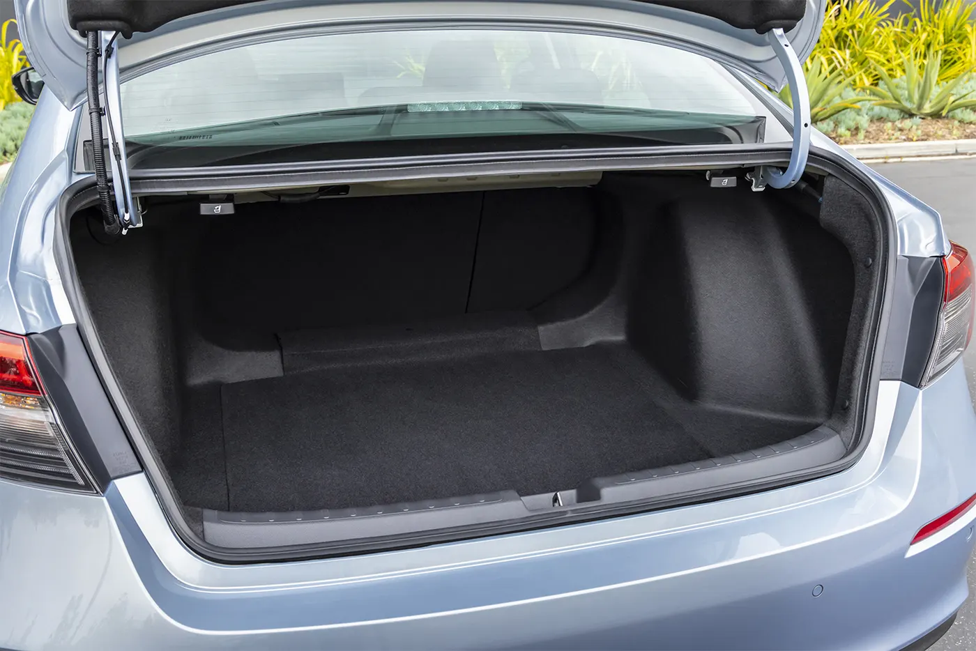
Basically, the Back door of a car is a component which hinges at the back of the car to cover the boot space or luggage area. These back doors are operated with the help of gas stays which in turn reduces the effort required to open the door.
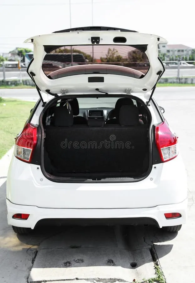
It not only provides the closure of the luggage compartment of the car but also provides the safety from any kind of impact from the back. If the door is hinged at the top it is termed a hatch. If the door is hinged at the bottom it is called a tailgate.
There are three types of backdoor:
- Top mounted
- Side mounted
- Bottom mounted
It is needless to say that the hinge axis will be at that specific position where the tail gate is mounted. This initial step helps us to determine the position of latch and striker.
Design Considerations of the BACKDOOR:
- Rear visibility criteria.
- Impact / crash test regulations.
- Proper sealing.
- Reinforcements.
- Draft analysis for manufacturing process.
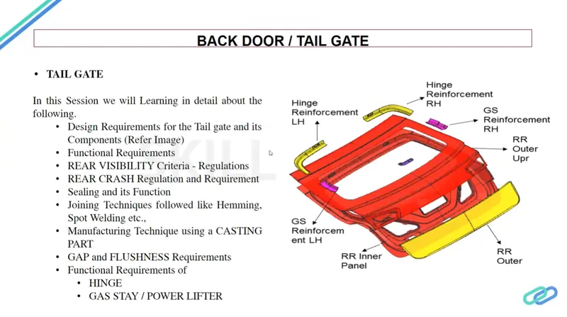
Parts of Backdoor assembly:
- Outer upper panel
- Outer lower panel
- Inner panel
- Hinge reinforcements
- Gas stay reinforcements
- Latch reinforcements.
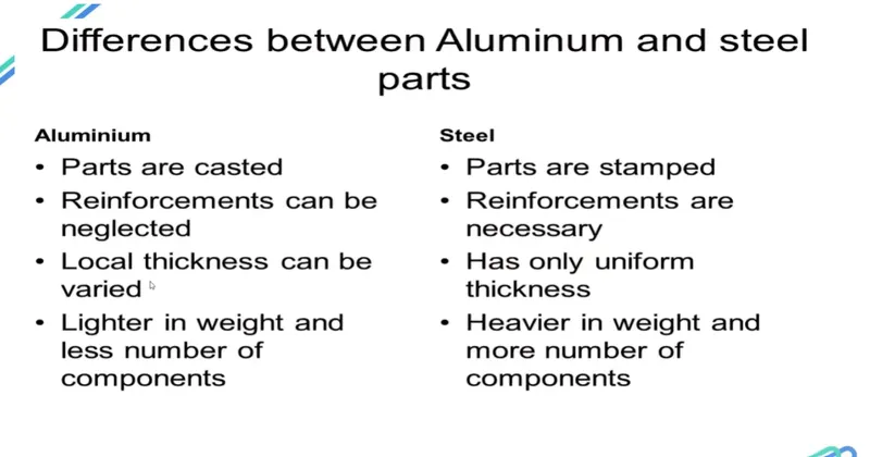
The most difficult and challenging part for the design of the back door is the material selection. The 2 most common material in the automotive industries used are steel and aluminium. The weight of the backdoor also affects the fuel economy of the car and also should be able to withstand the impact / carsh force also.
Aluminium has good strength to weight ratio and complex shapes can be easily obtained, whereas the steel is used in case of deep drawing process. Both the materials have their own advantages and disadvantages according to their properties and applications.
Various operation performed for the manufacturing of Backdoor:
1. Deep drawing.
Deep drawing is one of the most widely used processes in sheet metal forming. Apart from its use in many other sectors, it is applied in the automotive industry for the manufacturing of car body parts.
The deep drawing process is a forming process which occurs under a combination of tensile and compressive conditions. A flat sheet metal blank is formed into a hollow body open on one side or a hollow body is formed into a hollow body with a smaller cross-section. In the automotive industry, deep drawing is usually carried out using rigid tools.
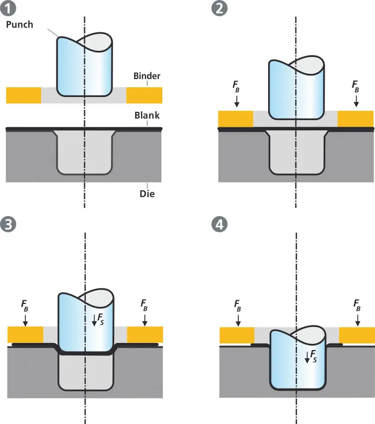
The figure illustrates the deep drawing process. The rigid tools consist of a punch, die and binder. In deep drawing, the plate holder closes after the metal sheet blank has been inserted.
Next the sheet is clamped between the die and the binder. This process slows down the flow of the sheet while it is being drawn and thereby prevents wrinkles from forming under the binder. The punch stretches the sheet over the die radius and forms it in the die. The amount of punch force necessary for forming is thereby continually increased up to the lower dead center of the punch.
Whereas in pure deep drawing there is no reduction of sheet metal thickness, forming is achieved in stretch forming purely as a result of a decrease in sheet metal thickness. Stretch forming is extensively used for the forming of only slightly curved parts with low depth of draw (e.g. roofs, doors).
When drawing complex car body parts in practice, there is usually a combination of stretch and deep drawing involved. It is necessary that the sheet metal is stretched as well as possible without reaching the material’s limits.
2. Embossing / Stamping.
Sheet metal embossing is a stamping process for producing raised or sunken designs or relief in sheet metal. This process can be made by means of matched male and female roller dies, or by passing sheet or a strip of metal between rolls of the desired pattern.
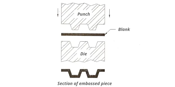
In sheet metal embossing, the deformation of the metal takes place because of stretching of the metal (or tensile force acting on the metal), due to which the sheet metal is subjected to excessive thinning and fracturing.
Thus the depth to which the material is depressed depends upon the thickness of the sheet as well as stretchability of the material.
Embossing is generally used to make dimples on sheet metal to increase their rigidity as well as it is also used for decorative purposes on panels.
3. Hemming
Hemming is a forming operation in which the edges of the sheet are folded or folded over another part in order to achieve a tight fit. Normally hemming operations are used to connect parts together, to improve the appearance of a part and to reinforce part edges.
In car part production, hemming is used in assembly as a secondary operation after deep drawing, trimming and flanging operations to join two sheet metal parts (outer and inner) together. Typical parts for this type of assembly are hoods, doors, trunk lids and fenders.
The accuracy of the hemming operation is very important since it affects the appearance of the surface and surface quality. Material deformations, which occur during the hemming process, can lead to dimensional variations and other defects in parts. Typical hemming defects are splits or wrinkles in the flange, material overlaps in the corner areas or material roll-in. This is why it is important to use simulation tools in order to, on the one hand, better understand the hemming process and, on the other hand, significantly reduce the number of “trial and error” loops during tryout und production.
There are various types of hemming operations:
- Conventional die hemming
Conventional die hemming is suitable for mass production. In die hemming, the flange is folded over the entire length with a hemming tool. Normally the actual hemming is a result of a forming operation in which the flange is formed with a hemming tool after the drawing and trimming operations have been completed. The formed flange is then hemmed in several process steps. These steps include, for example, the pre-hemming and final hemming depending on the respective opening angle of the flange. Production plants for conventional die hemming are very expensive, but the cycle times are very low.
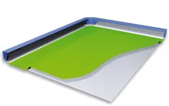
- Roll hemming
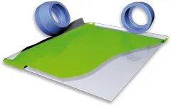
Roll hemming is carried out incrementally with a hemming roller. An industrial robot guides the hemming roller and forms the flange. Roll hemming operation can also be divided into several pre-hemming and final hemming process steps. Roll hemming is very flexible to use and tool costs are significantly lower as compared to those of conventional die hemming. However, the cycle times are much higher since the hemming is realized using a hemming roller which follows a defined path.
4. Punching
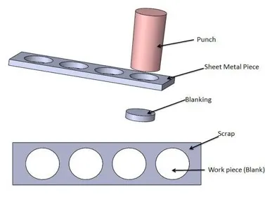
Punching is a forming process that uses a punch press to force a tool, called a punch, through the workpiece to create a hole via shearing.
Desing procedure of Backdoor:
1. Class A surface
The class A surface is obtained from the styling team. First we have to check the continuity of the surface using sew option.
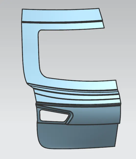
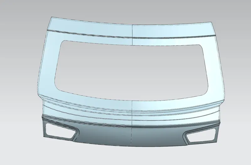
Given surfaces has to be repaired according to the smoothness using bridge curve and through mesh curve. After repairing the surfaces, the door is divided into two parts as Door Outer Upper and Door Lower Panel. Then they are extracted seperately.
In this design process, Top bottom approach is followed, which means the component are created in the assembly workbench itself instead of designing seperately and assembling them together. This saves the time and error that could be occured which designing.
We have considered a 2-part outer panel for our design, outer upper panel and outer lower panel prospectively.
Also, Inner and outer panels are connected by hemming process so we can come back to outer panel and do that that after completion of inner panel.
2. Outer upper panel
The outer panels are responsible for the looks, styling / aesthetics mainly. Outer panel is manufacture by stamping sheet metal. Thickness for outer panel is 0.75 mm
First the outer surface is offsetted considering the thickness of the outer and inner panel along with the clearance given between them around 0.2mm oon the either sides of the inner panel. Using offset curve in surface is used to create the hemming distance of about 8mm and trim the excess surface.
Using swept commad the curved surface is created and joined together using sew command.
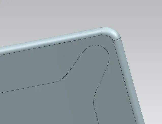
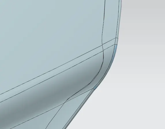
The Hemming is done on the outer and the inner panel with an clearance of 0.2mm on the either sides. Since at the corners the hemming is difficult to perform, clerances has been given at the ends of panels so that it would for the hemming operstion is performed.
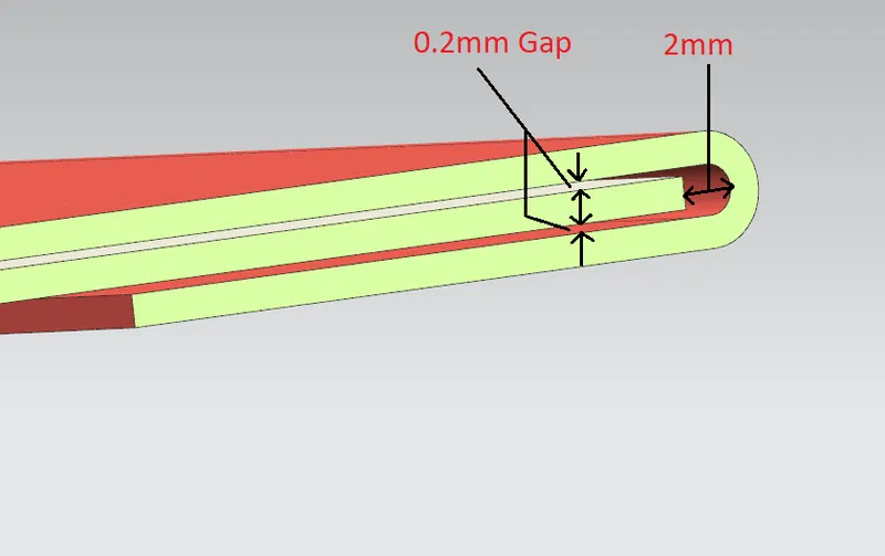
Also the reliefs are provided at the corner where their is more stress concentration as shown below.
At last the panel is mirrored and sew together.
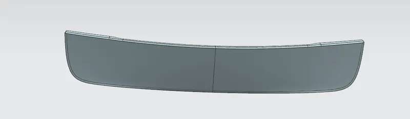
3. Outer lower panel
Similary to the design of the upper panel, the outer panel is also created.
4. Inner panel
First, we need to create the Tooling direction for the Deep drawing operation. All the operations like embossing is carried out by considering this tooling direction.
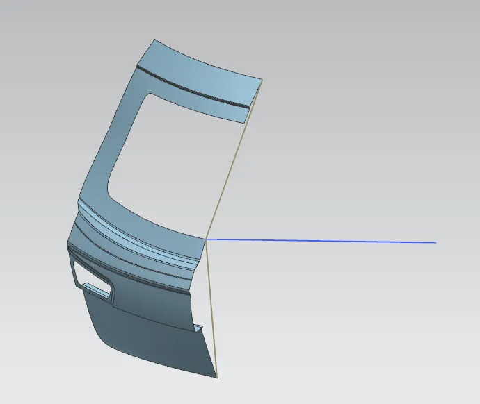
The surfaces are extracted each time after the completion of one part / component. After that we have to create Sealing Flange by offsetting the outer panel to the specific distance. Offset in curve option is used and a outer edge curves are used for a distance of 40-50mm.
The curve should have smooth transition. Now the offset of 30mm is given to the new curve for about 30mm which will the thichness of the sealing flange.
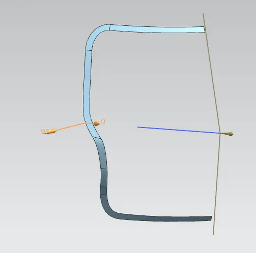
Both the side edges of the sealing flange is pulled using law extension with an angle of anout 15-20 degrees one side for the creation of connecting flange.
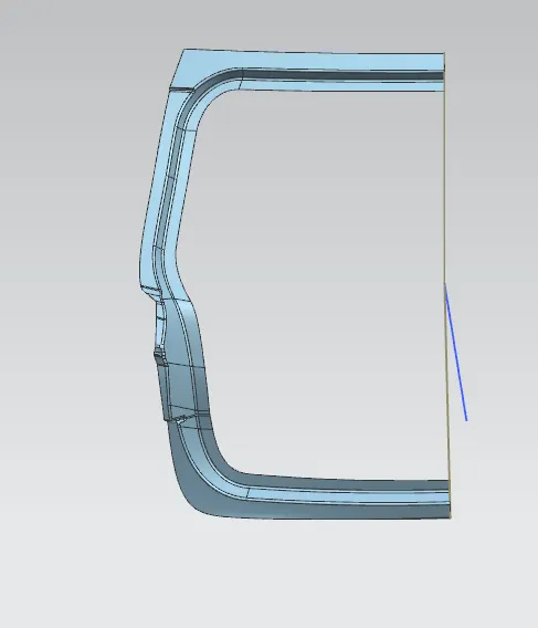
Then we will be creating the Back door inner panel flange by offsetting the outer surface at a distance considering the sheet thickness and thickening direction. The connecting flange and sealing flange are connected with the windshield panel using trim and extend command.
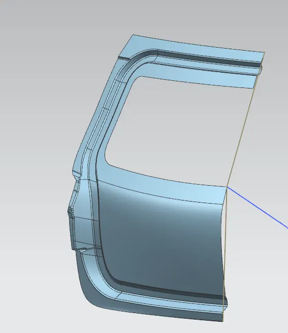
Now next various embosses and reinforcement attachment are created to improve the strength of the inner panel and to reduce the weight 'Y' type emboss and other cut-outs are created.
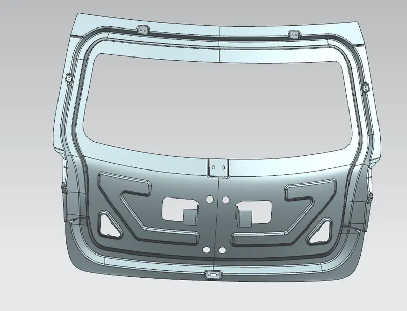
Another flange is created to reduce the vibration of door by joining the inner and outer panel with the help of Mastic sealant.
Reinforcements are provided to provide support and add extra material to the sheet metal part to increase its strength near component installation regions and minimize the impact of collisions.
5. Hinge reinforcement
To create the reinforcement the required surfaces are extracted first. Then the curve in surface is used to trim the sharp corners. Here the thicknes provided for the reinforcement is 1.5mm.
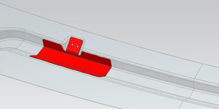
Simliarly the Gas stay and Latch reinforcement are created.
6. Gas stay reinforcements
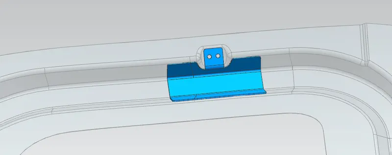
7. Latch reinforcement
The latch and striker reinforcement are created mainly responsible for the opening and closing of the back door. In order to ensure that the the centre point of the latch and stricker has to to be at the same point and the trajectory has to be tangent to the open close circle that is drawn.This is shown in the below image.
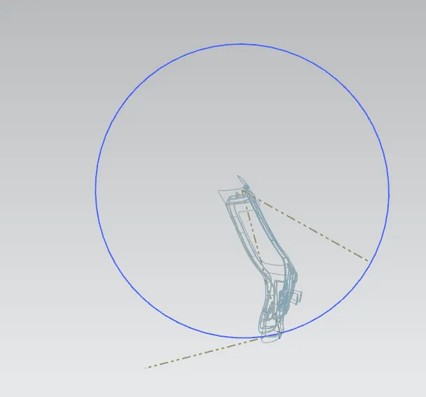
Only if the centre points and the tangent line are perfect the opening and closing of the back door is smooth and clear.
Draft analysis:
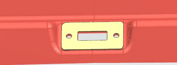
Draft analysis is carried out to check whether the inner panel and its components are passed the minimum requirement of draft fot the manufacturing of the sheet.
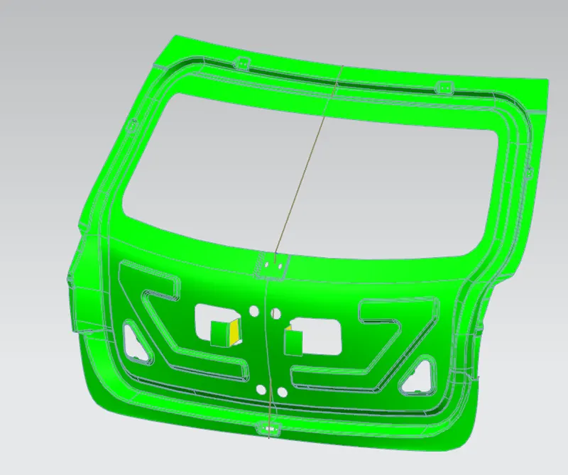
It can seen from the above image the panel is green that means it pass through draft analysis except for the one region shown in yellow which is performed using seperate operation after all is done.
The draft angle criteria is about 7 Degrees minimum.
Conclusion:
The back door outer and inner panel along with necessary embosses and attachments were designed with the help of the styling surface along the tooling direction.and
Draft analysis was performed on the inner panel and All the reinforcements were designed and placed at appropriate positions