Design of backdoor
DESIGN OF BACK DOOR OF A CAR USING NX CAD
INTRODUCTION:
Backdoor are one of the type of door of the vehicle which are located next to the passenger seat which provides access to the luggage compartment. In the most of the cars, these back door are operated with the help of gas stay which in turn reduces the effort required to lift the door.
OBJECTIVE:
In this project we are going to design the inner panel of the backdoor and necessary reinforcements which are going to require to produce it and also we are going to use industrial standards and design requirements which have been using in the industry and we will learn all of this in this project and we are going to make it by using NX CAD.
DESCRIPTION:
In this project we are going to see how we can design the back door inner panel and what are the things we have to take in consideration while making the back door.
MATERIAL SELECTION:
As of now we are using steel but aluminum parts are nowadays is been used because of the advantages it has over the steel parts.
Difference between aluminum and steel parts
Aluminum
- Parts are casted.
- Reinforcement can be neglected.
- Local thickness can be varied.
- Lighter in weight and less number of components.
Steel
- Parts are stamped.
- Reinforcements are necessary.
- Has only uniform thickness.
- Heavier in weight and more number of components.
FEATURES/TOOLS USED
- Sketch
- Extract geometry
- Offset surface
- Offset curve in surface
- Bridge curve
- Trim sheet
- Trim and extend
- Curve on surface
- Extend sheet
- Sew
- Mirror geometry
- Blend corner
- Edge blend
- Face blend
- Emboss
- Darts
- Swept
- Through curve mesh
- Surface curve mesh
- Thicken
DESIGN CONSIDERATION AND PARAMETERS
- Inner panel
- Hinge mounting
- Latch and striker mounting
- Gas stay mounting
- Wiper motor mounting
- Door handle mounting
Inner panel
We are going to design the inner panel by using the skin data or outer panel which is been given to us by the styling team and from that we are going to design the inner panel with the help of NX CAD.
While doing that we have to make some consideration which is how we are going to manufacture it and what method we are going to use to manufacture it.
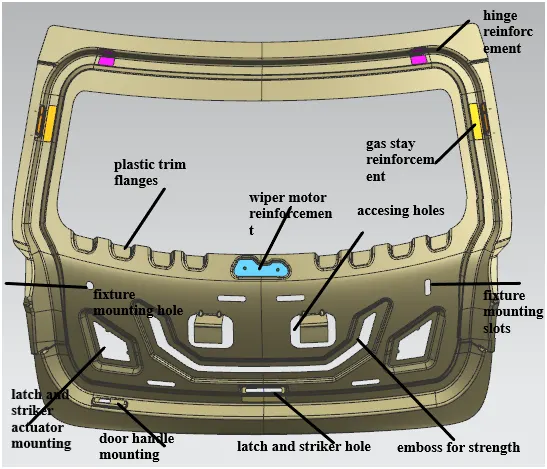
Inner panel
MANUFACTURING PROCESS:
We are going to use the deep drawing process:
The deep drawing process is a forming process which occurs under a combination of tensile and compressive conditions. A flat sheet metal blank is formed into a hollow body open on one side or a hollow body is formed into a hollow body with a smaller cross-section.
In the automotive industry, deep drawing is usually carried out using rigid tools.
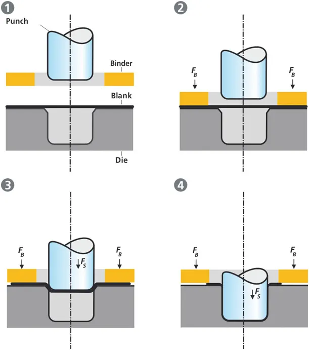
Illustration of the deep drawing process
The figure illustrates the deep drawing process. The rigid tools consist of a punch, die and binder. In deep drawing, the plate holder closes after the metal sheet blank has been inserted.
Next the sheet is clamped between the die and the binder. This process slows down the flow of the sheet while it is being drawn and thereby prevents wrinkles from forming under the binder. The punch stretches the sheet over the die radius and forms it in the die. The amount of punch force necessary for forming is thereby continually increased up to the lower dead center of the punch.
Whereas in pure deep drawing there is no reduction of sheet metal thickness, forming is achieved in stretch forming purely as a result of a decrease in sheet metal thickness. Stretch forming is extensively used for the forming of only slightly curved parts with low depth of draw (e.g. roofs, doors).
When drawing complex car body parts in practice, there is usually a combination of stretch and deep drawing involved. It is necessary that the sheet metal is stretched as well as possible without reaching the material’s limits (e.g. splits, wrinkles).
And for the inner panel we are going to tooling direction in that direction only the drawing process is going to happen.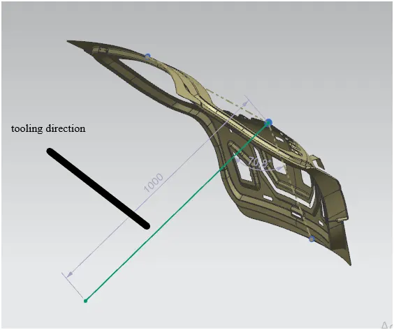
Tooling direction
So we are going to deep draw our part in this given direction by setting some positive draft in this we have given 7 degree of positive draft.
Now we are going to see the other mounting and reinforcement that we are going to give on it.
Hinge mounting and reinforcement
Hinges will help to rotate or to give a swing motion to the back door for that we are going to use hinges obviously there will limitation on how much the swing angle will be.
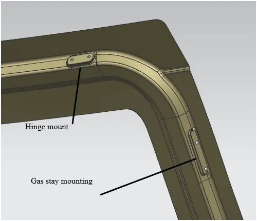
Hinge mounting is basically nothing but the mount on which we are going to mount our hinge so placing the hinge also have some consideration which is depends on whether your back door is a gas stay mounted or power spindle mounted on the factor of that we have to place our hinges according to that if it is a gas stay then the hinges will be placed inside the back door and if it is a power spindle one then the hinges will be placed outside the backdoor which will be visible but will be having a plastic cover on it.
And as we are going to use a gas stay so our hinge placement will be on inside the back door of it.
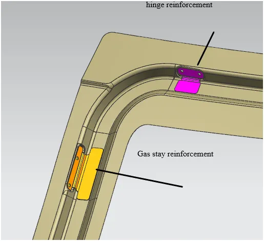
After giving the hinge mounting that area of the part will be weaken so for compensating that we are going to add reinforcement which will strengthen the part on that particular area.
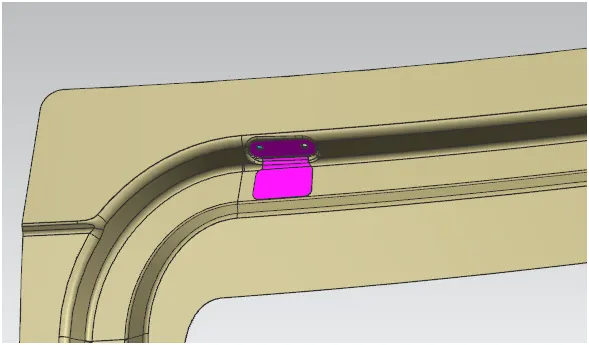
Hinge reinforcement
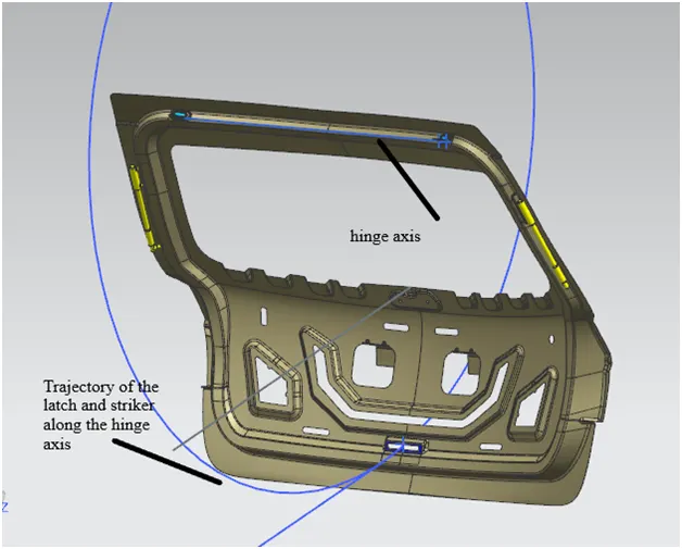
And the latch and striker positioning will be also decided according to the hinge axis
Hinge axis
In the above image you can see that the trajectory of the latch and striker along the hinge axis will be dependent on the placement of hinge so it is very important to get that position properly so that we can have proper motion of the latch and striker.
Gas stay mounting and reinforcement
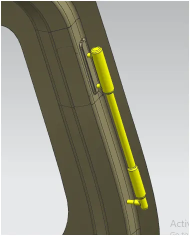
Camloc gas struts work by forcing, under pressure, an inert gas (Nitrogen) into a cylinder. The internal pressure then greatly exceeds atmospheric pressure. When the rod is compressed into the cylinder, the internal pressure and the output force increase according to the volume displaced by the rod.
Hinge and gas stay mounting
Hinge and gas stay reinforcement
Gas stay
The gas stay one point will be mounted on the inner panel and the other point will be mounted on the body of the car.
Also we have to consider the length and the angle between the gas stay and the hinge shouldn’t be more than 60- 90 mm in length and the angle also should be in between 80-90 degree this value was considering several trial and errors and tests and according to that we have found this values.
Latch and striker mounting and reinforcement
Striker is the part which is going to get engage with the latch in order to open or close it so as I mentioned above that the latch and striker position is decided by the hinge axis and the placement of the hinge.
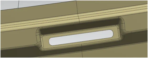
Latch and striker mounting
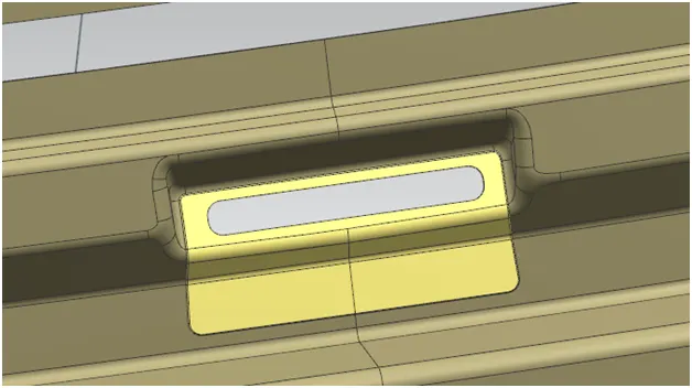
Latch and striker reinforcement
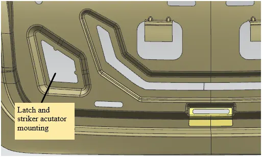
Latch and striker actuator mounting holes
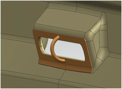
Striker
Wiper motor mounting and reinforcement
We are going to make wiper motor reinforcement and mounting on the inner panel so that we can mount wiper motor on the back door.
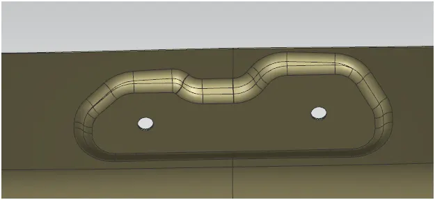
Wiper motor mounting
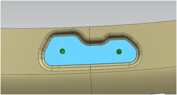
Wiper motor reinforcement
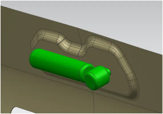
Wiper motor
TESTING METHODS OF BACK DOOR
- Bend test
- Torsion test
- Abuse test
- Dent test
- Assembly load case
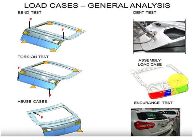
- Endurance test
- In bend test we are going to bend the part by fixing the four corner points of the back door and applying load at the middle of it after applying the load the part should regain its original position.
- In torsion test we apply a couple force by fixing the other ends of the part its basically twisting of the part you can say.
- In abuse case its is normally when someone is hanging on the backdoor while in open condition of the back door so the person will apply force on that point where he/she is leaning on.
- Dent test in which the load is applied on the panels to see how much force they can withstand.
- Assembly load case is in which the load which is getting applied while the part gets assembled so that is also we have to test whether the assembled part can withstand itself or not.
- Endurance test is where the back door is opened and closed number of times and after that the results are been observed.
DRAFT ANALYSIS
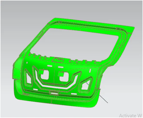
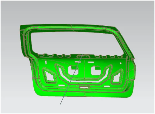
We are going to do draft analysis on the inner panel as it is going to be made by deep drawing process so we will do the draft analysis by giving 7 degree of positive angle to it. It basically show whether your part is going to be produce without creating any hindrance to the punch that is going to return after punching it.
And we are going to do the draft analysis by using the tooling direction which is basically our direction on which our part is going to be deep drawn or pressed.
Draft analysis
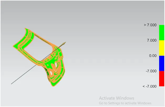
The green part shows the regions where it is having a draft angle of more or equal to 7 degree which means the part is passed.
The yellow region shows it is having a draft angle of 7 to 0 degree.
The blue region shows it is having a draft angle of 0 to -7 degree in this region it is going to have negative draft which is not acceptable cause the die will stuck after process.
The red region shows the draft angle is equal or more than -7 degree which is absolutely shows failure cause we doesn’t want a negative draft on the part so we have to make changes according to that.
HEMMING
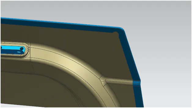
Hemming is the process where you join two parts by bending on part on the other one
We have used a open hemming in this the bend angle should be 180 degree and we have given the necessary mastic points which should be 5 mm in between the outer and inner panel and we are going to attach the outer surface by using hemming.
Hemming
And we also provided relief on the corner edges as it tends to fail means it can get wrinkles or spilt which is ultimately bad and also it relieve the stress on the corners.
and we also provided embosses to the inner panel to give strength we did the "Y" shape emboss to dissipiate the collision energy to make it minimal while in the rear crashing condition and provided necessary embosses and reinforcement
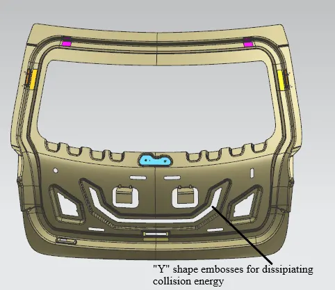
and finally assembling every part and doing thickening to it we did the thicknening by 0.75mm.
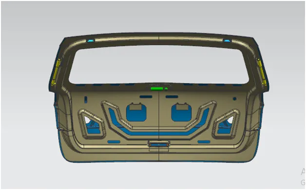
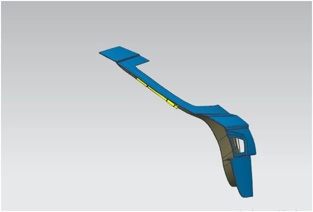
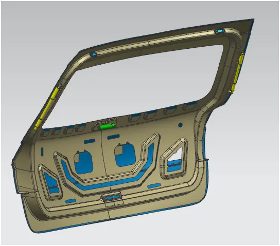
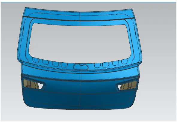
Final part
CONCLUSION:
We are successfully able to design the back door and learn the manufacturing process and design requirement as per the industry standards we are able to learn new features and made the part successfully in NX CAD.