Design of backdoor
BACK DOOR PROJECT
Back door are important aspect of vehicle design as they facilitate access to the cargo or passenger compartment.The design of back door has evolved over time to meet changing requirements and preference of vehicle owner.
There are various types of back door are as
<!-- [if !supportLists]-->1. <!--[endif]-->Swing out back door
<!-- [if !supportLists]-->2. <!--[endif]-->Lift gate back door
<!-- [if !supportLists]-->3. <!--[endif]-->Sliding back door
Barn door back door - this is unique type of back door as it opens horizontally like double door
Measures of back door design have taken from roof design engineer to feet it properly over outer line of roof and meet it properly.
Also hinge are placed of outer or inner body of roof outer panel or inner so it is important to take data from roof designer to design back door.
Features on back door :
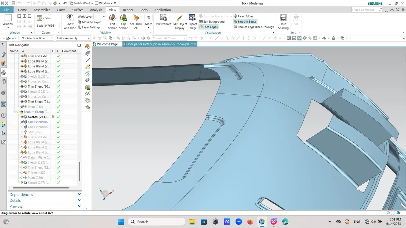
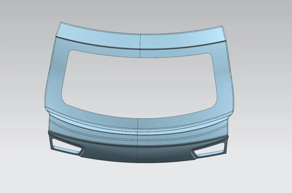
Back door is divided into two section one is upper body and other is lower body there is inner body of back door on inner body there is emboss for hinges and gas stay also there some cut out provided on it for tel lamp and as well some embosses for force distribution and also wiper motor emboss and striker emboss .
Design consideration for the tail gate and its component functional requeirments:
<!-- [if !supportLists]-->4. <!--[endif]-->Rear visibility criteria
<!-- [if !supportLists]-->5. <!--[endif]-->Rear crash regulation and requeirments
<!-- [if !supportLists]-->6. <!--[endif]-->Scaling and its functions
<!-- [if !supportLists]-->7. <!--[endif]-->Joining techniques followed like heming,spot welding etc.
<!-- [if !supportLists]-->8. <!--[endif]-->Manufacturing techniques using a casting and stamped process.
<!-- [if !supportLists]-->9. <!--[endif]-->Gap and flushness for removal of dust and rainy water.
<!-- [if !supportLists]-->10. <!--[endif]-->Functional requirement
Hings and gas stay/power lifter.
Manufacturing Process.
By casting and stamping process:there are two types of material used accordance to manufacturing process are as aluminium and steel
Aluminum >casting | Steel >stamping |
<!-- [if !supportLists]-->l <!--[endif]-->Parts are coasted <!-- [if !supportLists]-->l <!--[endif]-->Inner panel can not deep draw but outer panel can deep draw. <!-- [if !supportLists]-->l <!--[endif]-->Can vary thickness at different region. <!-- [if !supportLists]-->l <!--[endif]-->Lighter in weight and less of component <!-- [if !supportLists]-->l <!--[endif]-->Deep draw angle is low as 3 deg to 2 deg in aluminum so more space can create. | <!-- [if !supportLists]-->l <!--[endif]-->Parts are stamped <!-- [if !supportLists]-->l <!--[endif]-->Inner panel can deep draw but reinforcement required at engineering features as hinges,gas stay.striker etc. <!-- [if !supportLists]-->l <!--[endif]-->Thickness can not vary that’s why reinforcement required. <!-- [if !supportLists]-->l <!--[endif]-->Has uniform thickness so it becomes heavy and number of components also increase. <!-- [if !supportLists]-->l <!--[endif]-->Deep draw angle is more so consumes more space its 7deg in steel parts also increase manufacturing coast. |
Load Bearing capacity.:
There are various tests performs on back door.
Bend Test :in this load is applied of both end of door form up side to see how sustainable it against bending load .
Torsion test:in this load is performed on both end in opposite direction try to twist it up certain limit to check its suceptable it against load.
Abuse test: abuse case, we examine the causes of over slamming or hanging when the door is open. Because some people tent to lie on the door when the door is open.
Dent test:It is done to evaluate whether dent is coming back to its original position.
Assembly Load case:Assembly load case is examined to check the backdoor during assembling the vehicle, how much force is given to the body and whether the door is withstanding or not?.
Endurance test:It is the work ability tests. The backdoor will be opened and closed for a particular number of cycles. And we see how the door behaves at the end of the cycle. If it’s a side door the number of cycles will be more. If it is back door the cycle will be relatively less. Because we don’t open that many times.
Creation of back door :
Given class A Surface :Class A surface provided to us may have some irregularities we have to settle down them to get one finished and proper surface for that we hide that particular surface and and by using through curve and studio surface recreate those surfaces and then joined them properly by sew operation.then extracted those surface copied to past at different place by name of upper panel and lower panel.
Assembly : Back Door
Create an assembly and named it as back door assembly,then
create model and open previously past part to it then named it outer panel upper fixed it again
create second model and past previously copied part to it named it as outer panel lower fixed
Create one more model and named it as inner panel
Inner Panel:-
Reference Surface:
Activate inner panel and by using wave geometry linker extract outer panel upper and outer panel lower.
Working Surface:Then extracted both the outer and lower panel particularly.
Tooling Axis: then went to sketch and select plane and drew two lines connecting two extreme points and then bisect them by bisector and used those parents lines as reference.
Offset:By using those extracted surfaces offset them by distance of 1.7mm downword .for both outer and inner panel .
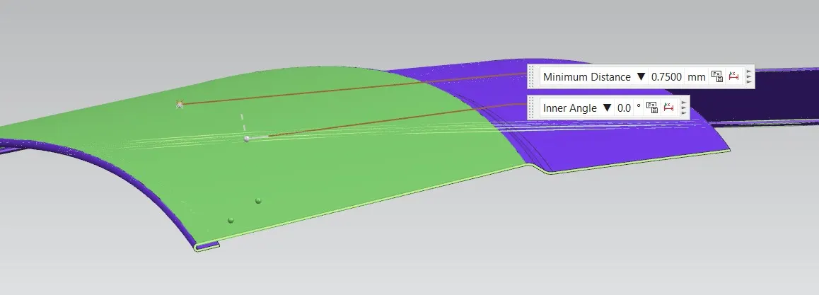
This is distance calculation of 0.75*2+0.2
Creation of Rubber seal:
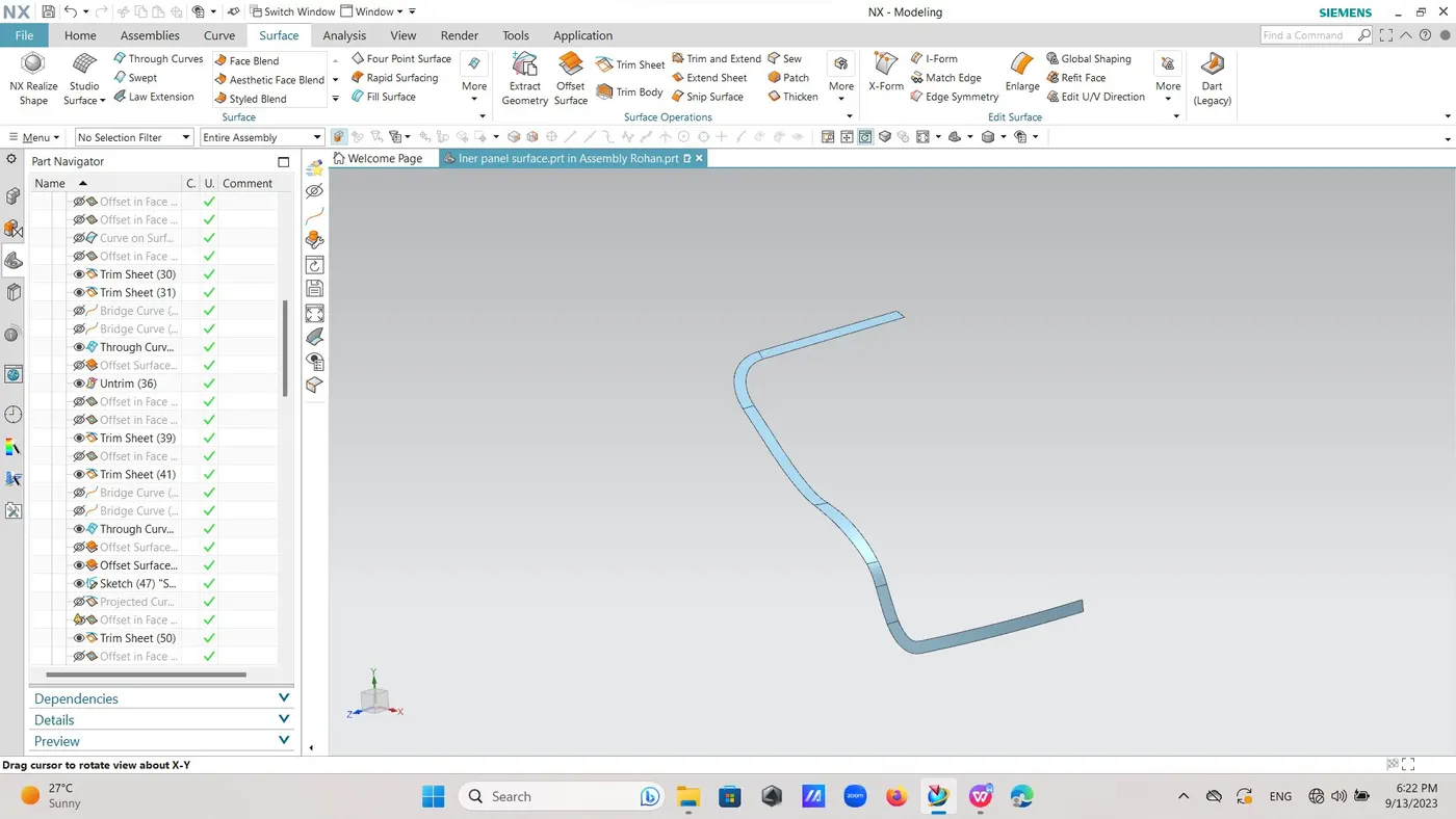
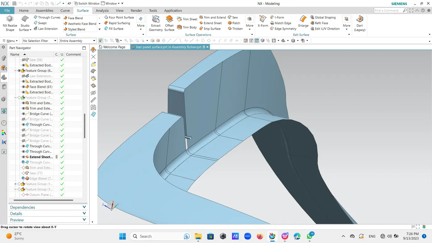
Now offset upper surface by distance of 25mm downword for creation of rubber seal then we ll work on offset surface by using offset curve in face through curve option we offset edges by distance of 50mm and by considering that offset line we offset same edge by distance of 5mm.we have to keep distance of at list 14 to 18mm from edges of the surface so accordance of this we are offsetting those lines now trimmed those lines and by using bridge curve option we drawn curvatures to join different lines together then we used through curve option for joining those surfaces.in case of tell light portion we offset it to match surfaces offset distance and then and untrimmed at that portion then also offset line by distance of 14mm we trimmed it off we used bridge curve to join those curve and through curve mesh to join those surface.
For lower body surface we select to draw a sketch and then project them on particular surface then trimmed them off and by using bridge curve and through curve option we join those surface after all that we sewed those surfaces properly to get one complete portion.
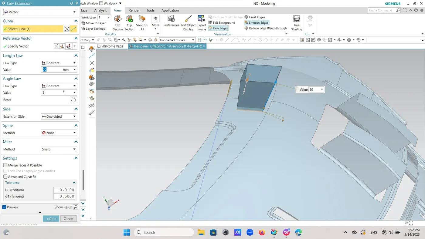
Extract that surface and them by using law extension command we used outer edge of that body for law extension and by using outer angle of 24 deg up to 80mm .we extract law extension also then by using face blend command we join two surfaces.
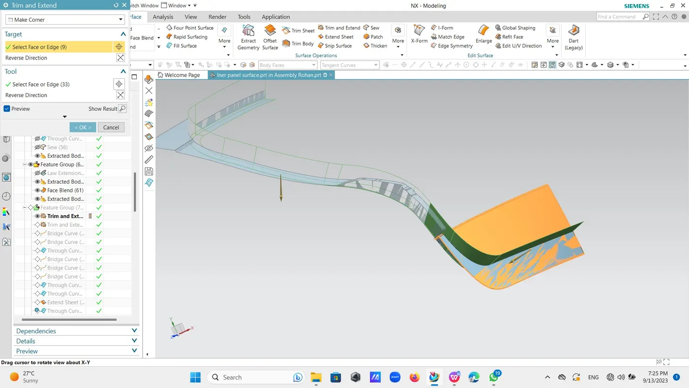
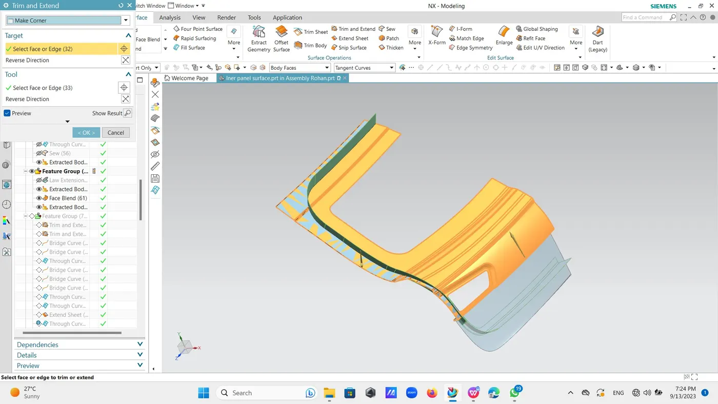
Extract this body for trim and extend upper and lower surface separately.for creation of outer ring. Then for U shape portion used bridge curve and through to create that surface.extend U shape out side trimmed it with rectangular portion of through and then sewed all the surfaces.
Then by using edge blend bled the sharp corners with particular radius.
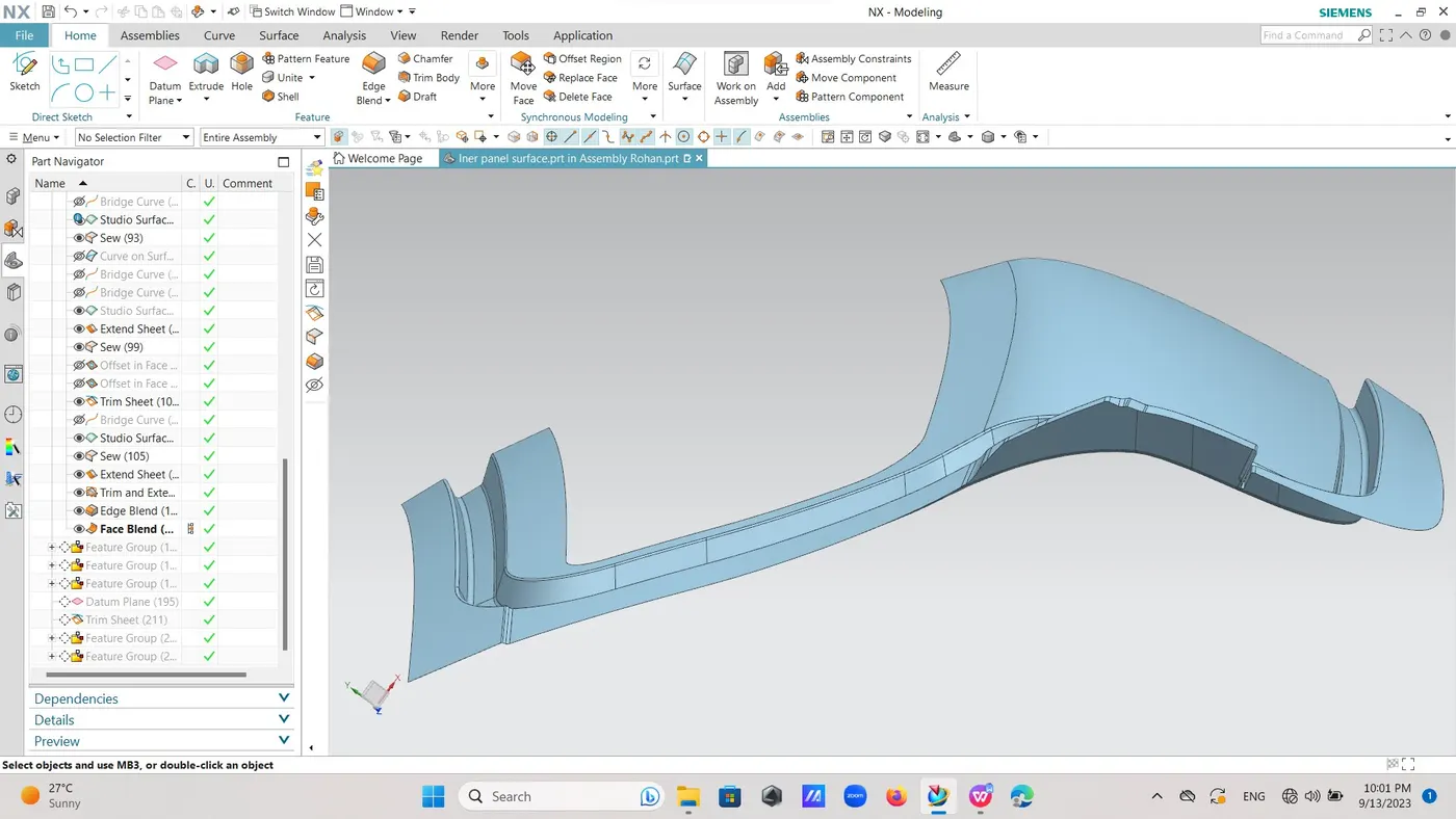
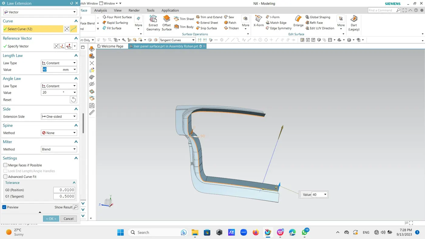
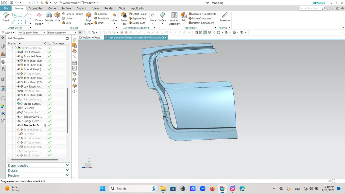
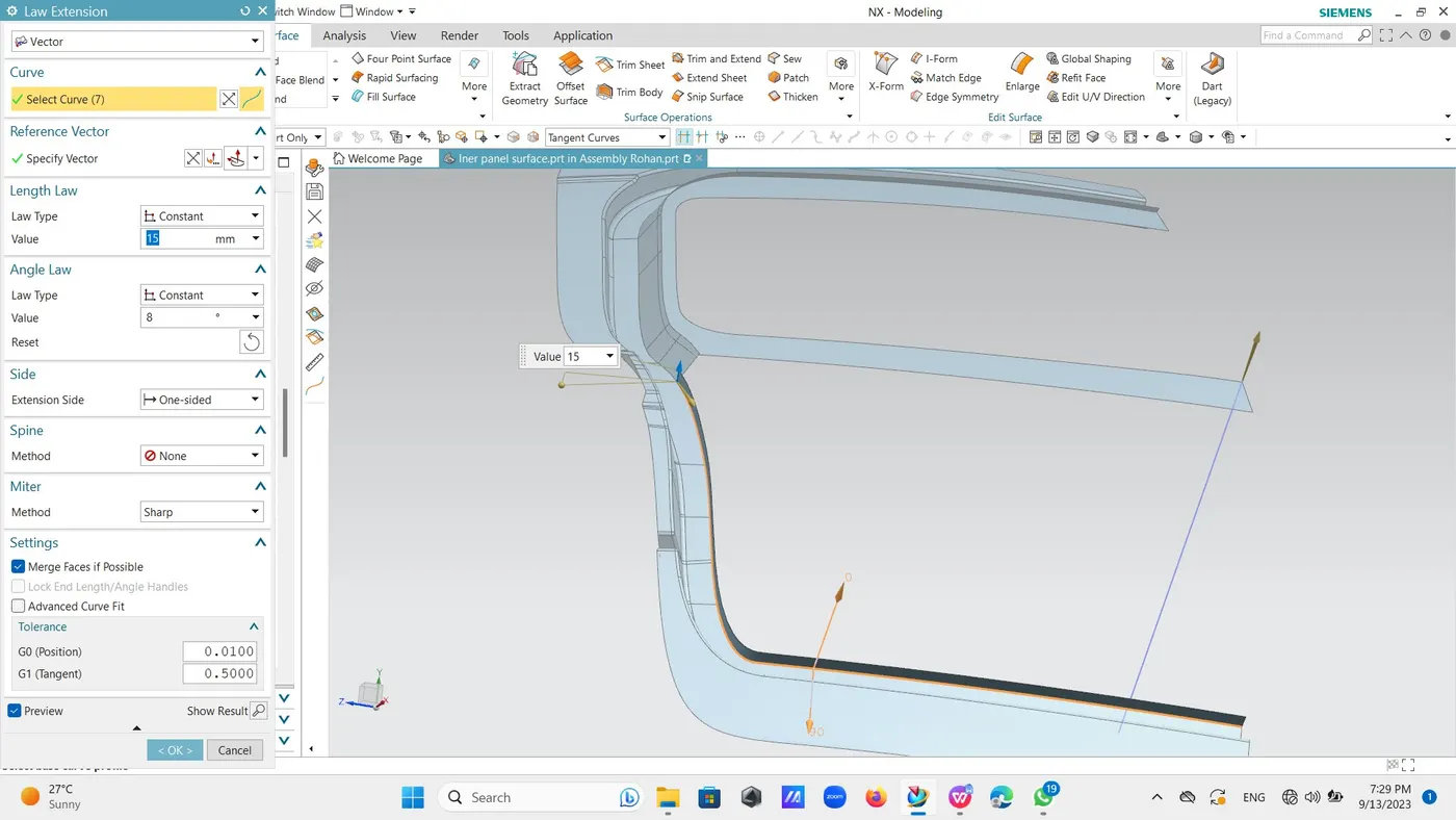
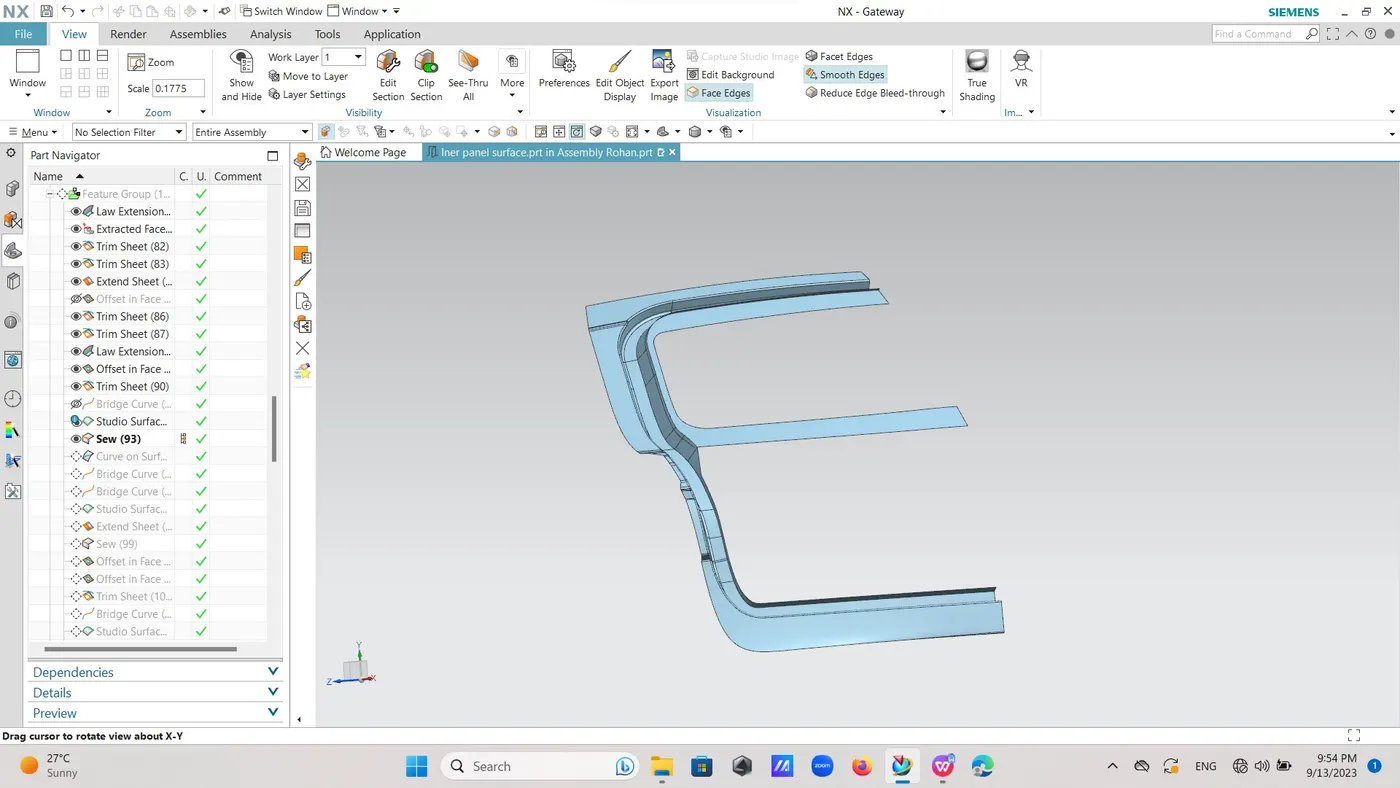
Wind shield:Took inner edge of offset-ted surface of and used law extension command through which it is kept angle of inclination 20deg and vector as tooling axis in upward direction then extracted upper body surface partially and then by using trim and extend trimmed that surface.
Then broke lower law extension in half because we want lower height than upper surface law extension and inclined it by an angle of 8 deg inward for making proper inner lower surface.
Then by using bridge curve option drew two guide curve for proper surface guidance,then took a studio surface command and and drew one surface that one is extended beyond limit to penetrate lower law extension and then join this surface with upper surface and two law extensions by extending its height then trimmed it off by using trim and extend command and made corner there then used a edge blend command and blend it .
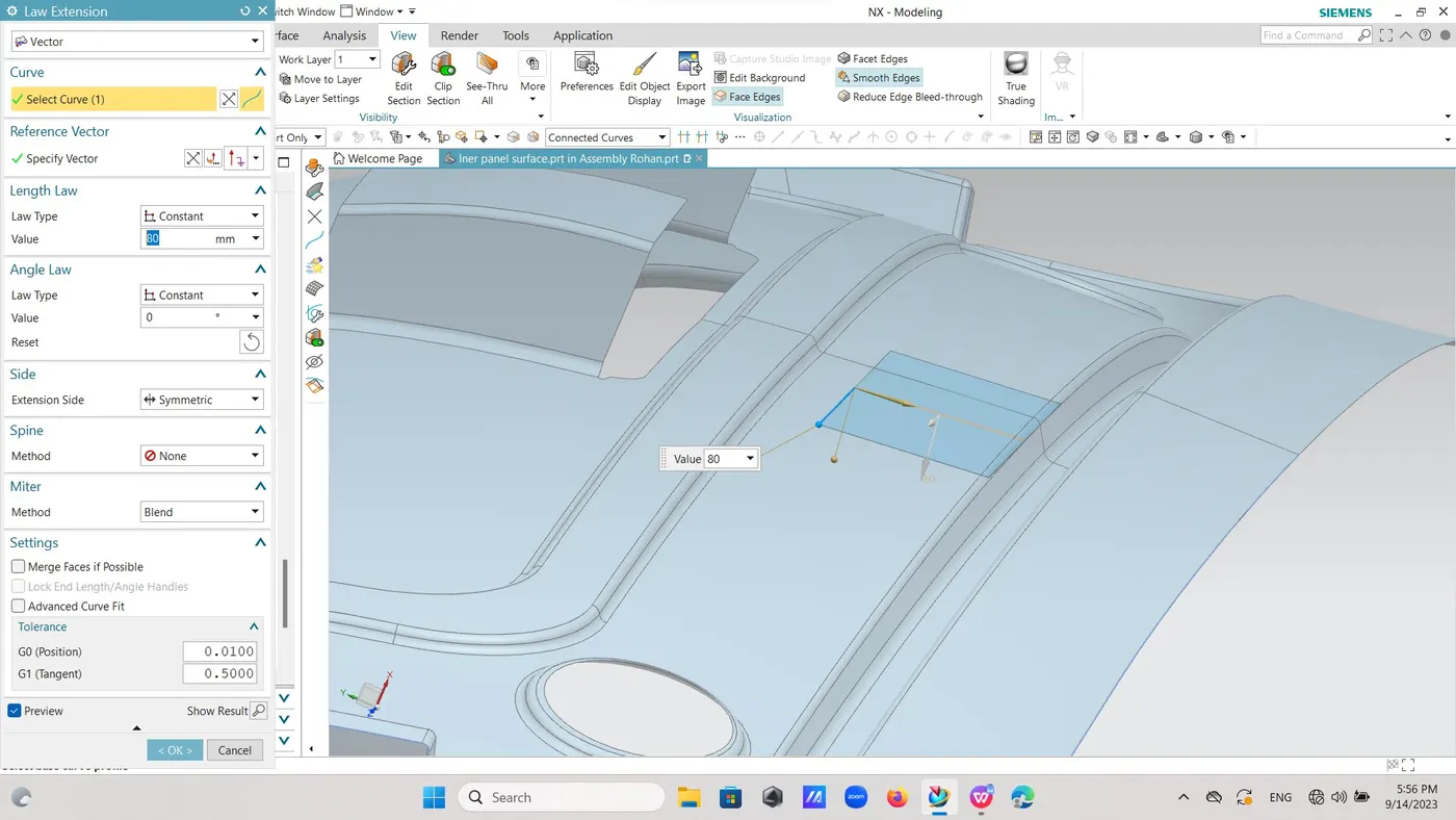
Heat stay creation:-In heat stay creation took a datum plane at certain distance from corner and then go to view option and cut this portion and took clip section then go to sketch and select that datum plane and then drew one line inclined two corners then came out of sketch and used law extension command in symmetry option and extend that line in two sides changed angle according to settle it inclination to parallel and then took a law extension command by using connected curve upward outward then sew two surfaces and trimmed them off to get heat stay pocket then by using edge blend option blend firstly two opposite sides and then used tangential edge and blend it .
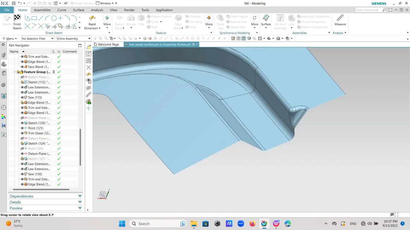
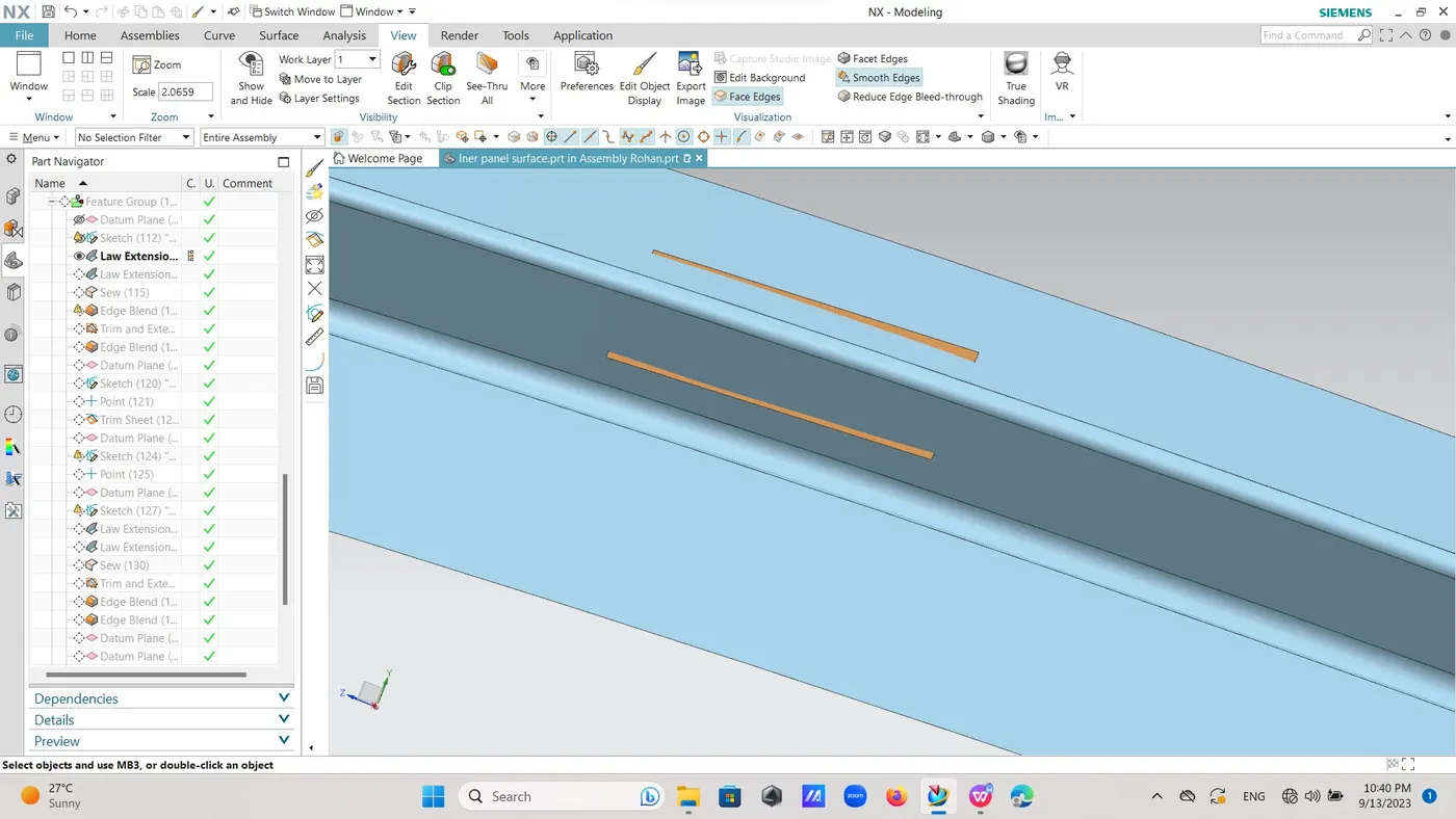
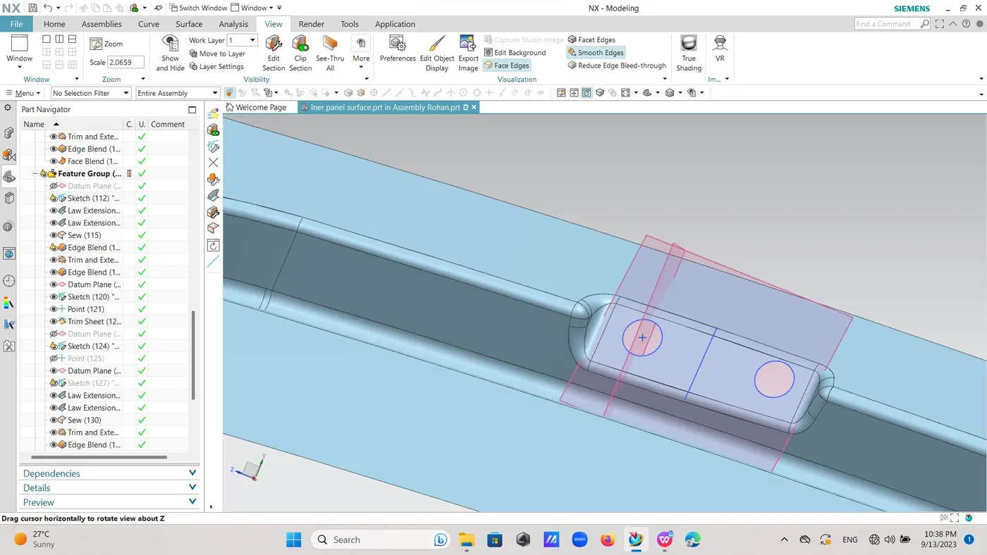
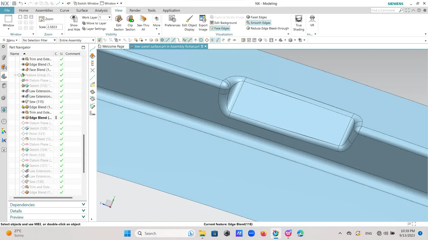
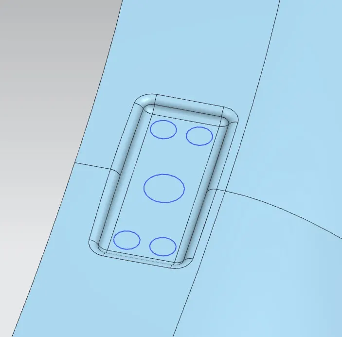
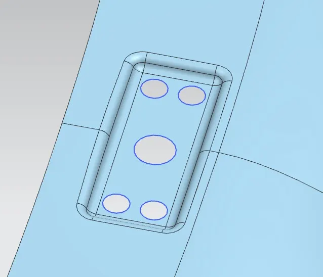
Then took a datum plane three point and drew sketch of two circles came out of it trimmed that circle .
Took 3D point and again drew a sketch of line perpendicular .
Same procedure followed for gas stay also.
Engineering Features on lower surface:-
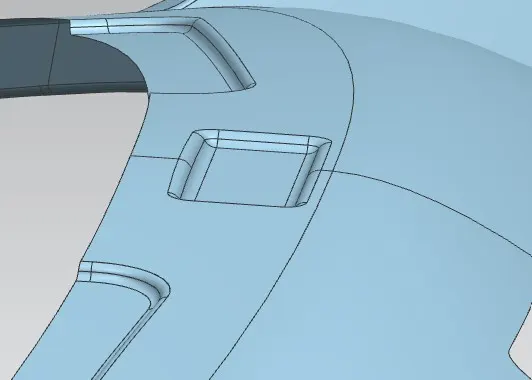
Made one rectangular cut out on lower surface then
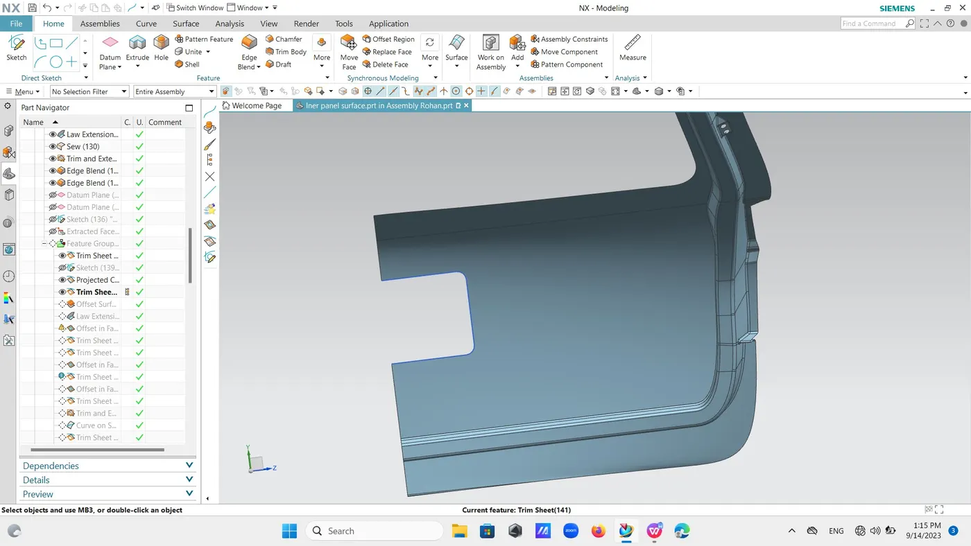
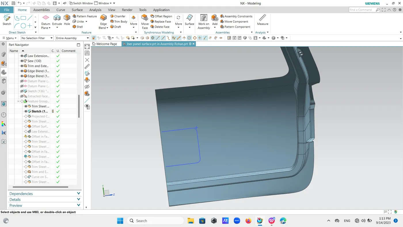
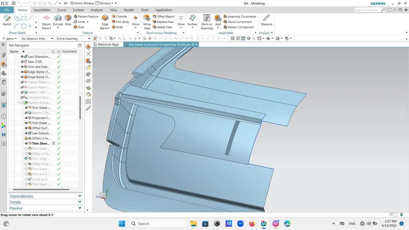
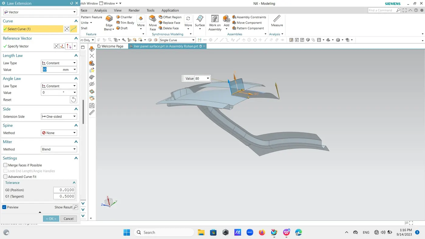
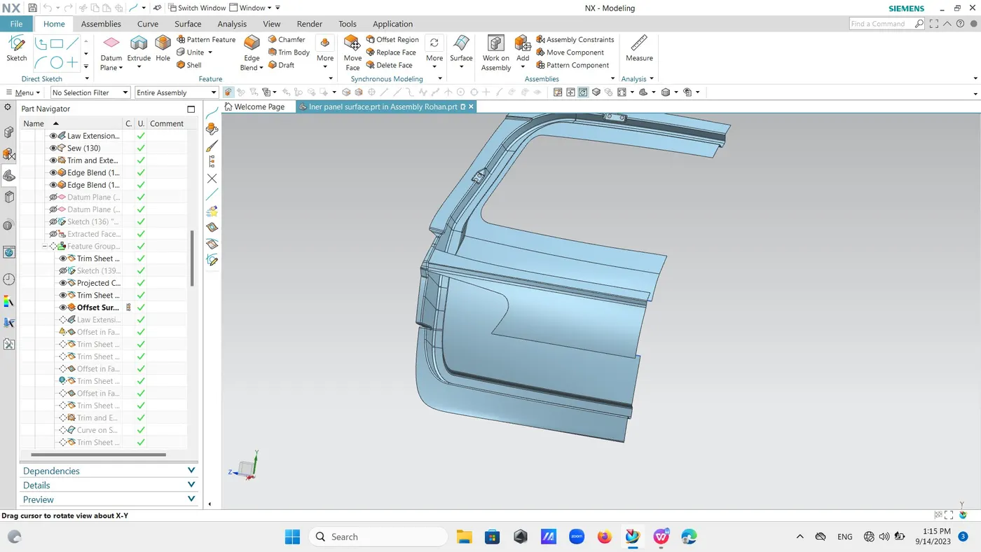
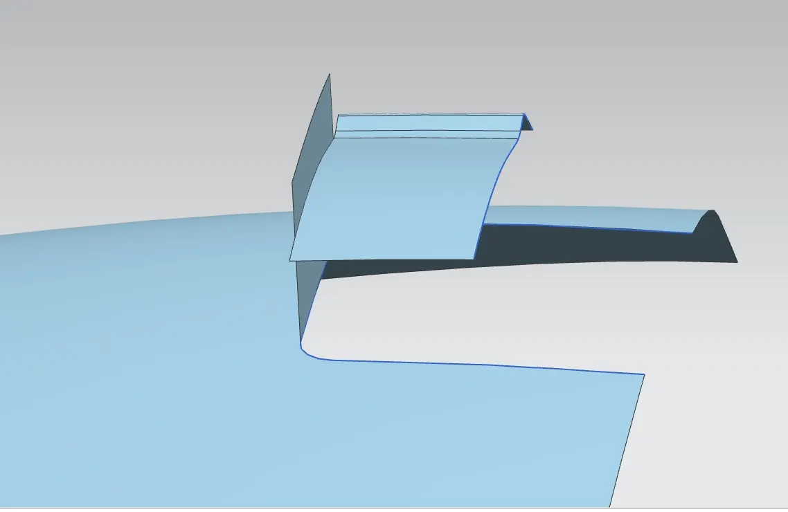
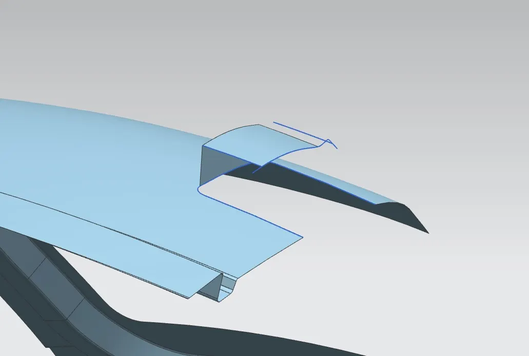
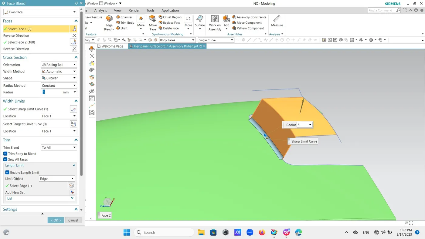
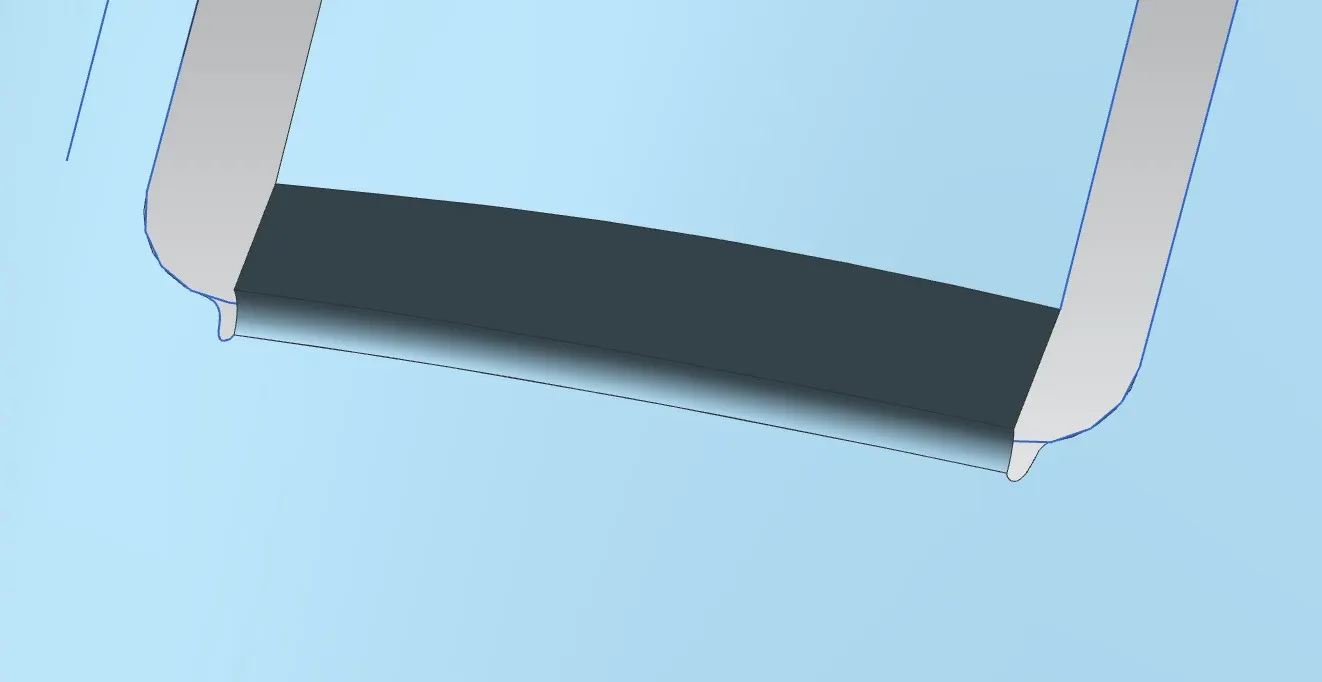
offsetting extracted surface downward by distance of 5mm then offset lines on surface towards rectangular cutting lines and trimmed of excess surface.
Then again offset same line by distance of half of its rectangular distance and trimmed off excess surface to get horizontal surface
Then picked up horizontal line and used law extension command tooling direction as is tooling axis and make corner with that horizontal surface and give fillet to edges by face blend option through surface .
For lower edge we can not give direct blend option we set limit curve for this and then cut excess portion of that surface.
Relief : we provide relief at lower edge by using curve on surface drew curve on both sides and then trimmed it off on sides of the surface.
Command : curve on surface>surface>trimmed off
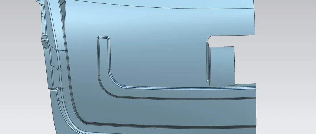
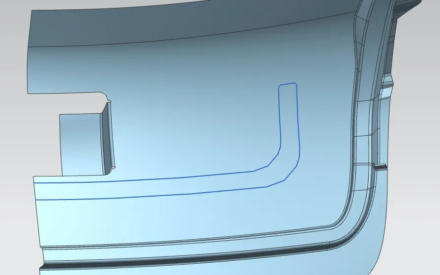
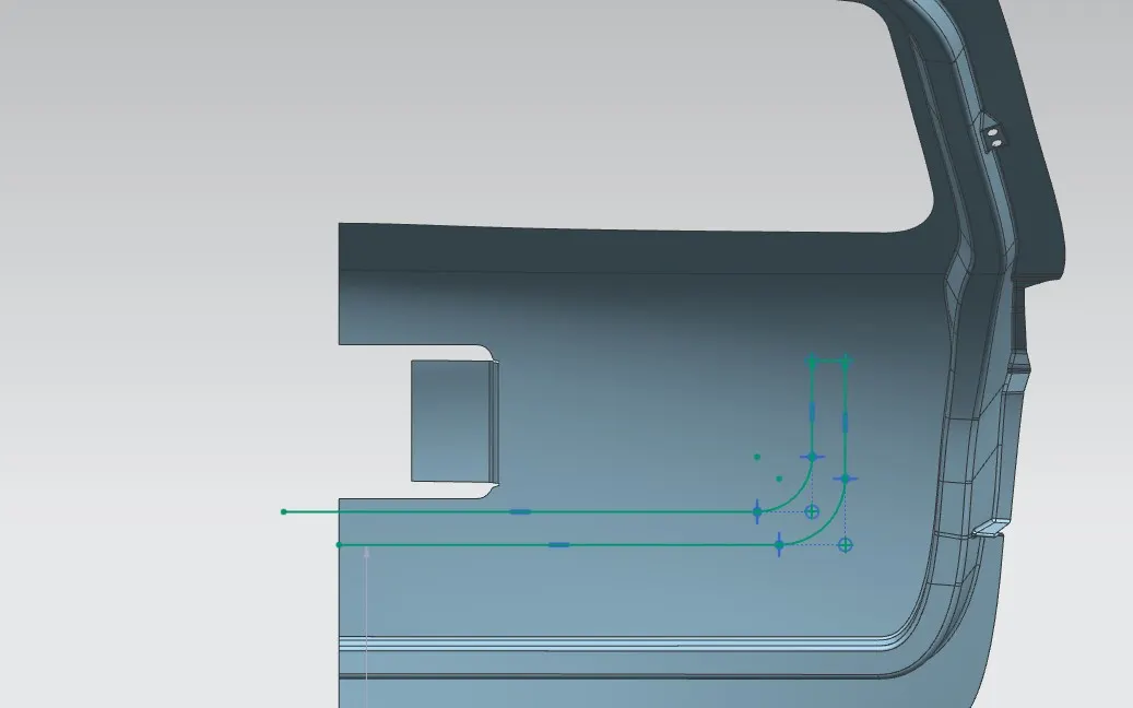
Upper Emboss: Took a plane as three point then select three points on surface and drew a sketch on it of rectangular size of some predictable dimension and go to curve option beside of that surface and then project this sketch along normal direction on the surface then go to surface more emboss select given sketch and emboss it with vector direction as tooling direction by 5mm distance to downward direction.
Command: datum plane>curve and points> three points+sketch>curve>project curve>Surface>more>emboss>edge fillet.
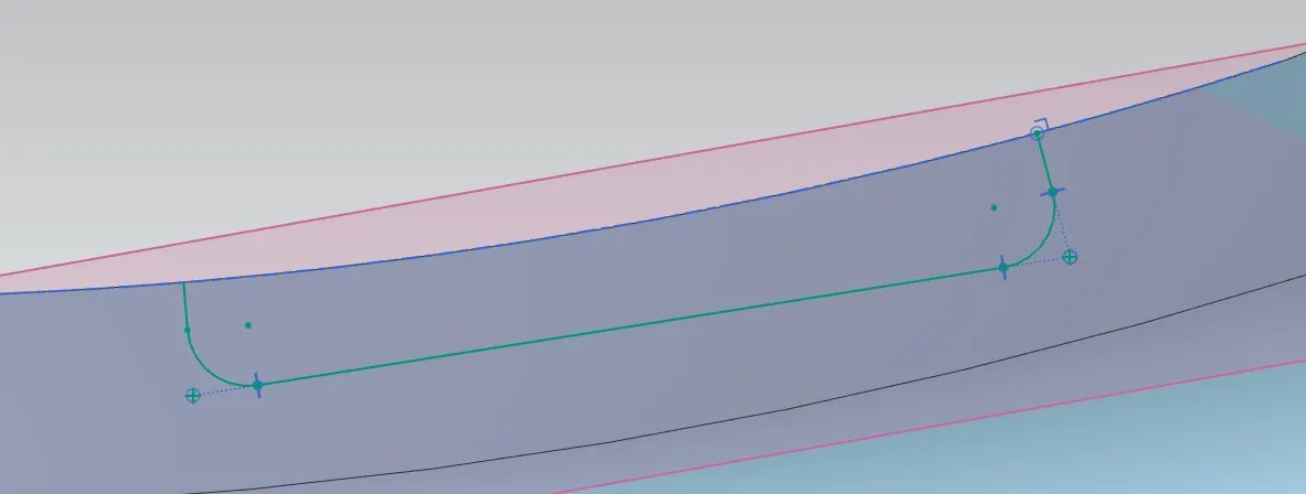
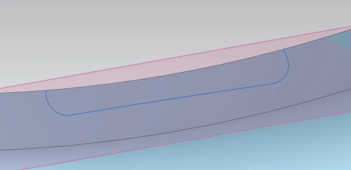
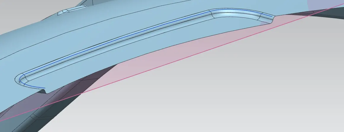
Linear cut out and emboss:-
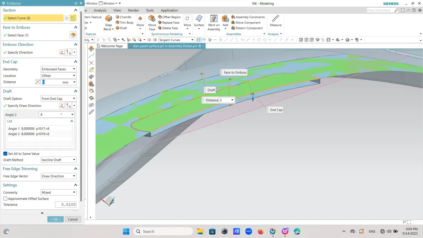
Same as above took a datum plane then curve and point then three point go to sketch select co ordinate and vector direction drew a rectangular sketch constrained it and go to curve then project curve and project that curve on given surface then go to surface and more option go to emboss then select tooling direction and then given an emboss of 5mm to words upward fillet
Offset boundaries of that rectangle inside then go to surface and trimmed them to protrude that surface.
Force here is working form downward size so that it must go out side direction that’s why this provision is given there.
Command: datum plane>curve and points> three points+sketch>curve>project curve>Surface>more>emboss>curve offset curve>surface>trim surface>edge fillet.
Circular cut out:
Took same three point plane then drew one sketch on it of circle came out of it and project it on given surface then go to surface and emboss out side drew same sketch and trimmed that another sketch by protrude that circle .
Command: datum plane>curve and points> three points+sketch>curve>project curve>Surface>more>emboss>curve offset curve>surface>trim surface>edge fillet.
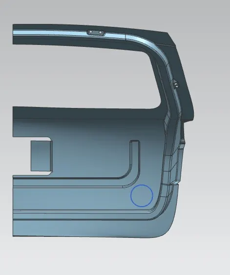
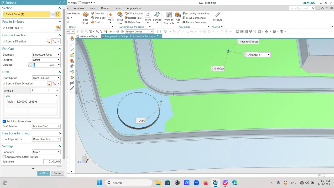
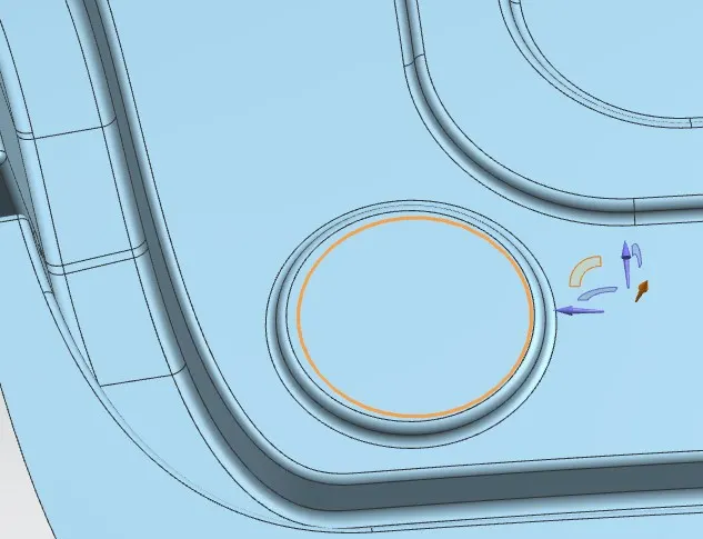
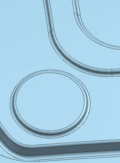
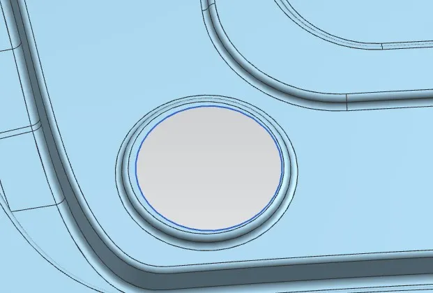
Associative copy:-Now extend sheet by 5mm to trim it off equally
Corner relief: go to curve select bridge curve option took 8mm by length on both side and then trimmed it off .
Go to insert -Associative copy -Mirror Geometry then Mirror it.
With this.
Striker mounting:- drew perpendicular line through point taken as 3d point previously then mirror it on other side.
Drew a 3D line through extreme points of that line ,then took a datum plane along curve by percentage of 50% to get it middle.
Go to view edit section select that plane and then clip section then cut half of its surface for better view then drew a line below surface at about 5mm and then go extension tool that line as curve choose as symmetry extend it by 30mm and adjust its angle then go to law extension again choose composite curve took angle as 12deg for friction less removal of punch and extrude it upside sew both surfaces and trimmed this with lower surface then go to edge blend and blend its edges.
Drew new plane as three point plane drew new sketch of four circle project it on surface and then trimmed those circle to get punch hole.drew middle hole so and punch it.
by taking that plane as reference drew a sketch of circle called as trajectory circle drew a horizontal line with center of circle as starting point of it then drew one another line with and angle of 84deg and one another tangential line by keeping on point of intersection and intersect that point with center of striker central key hole.
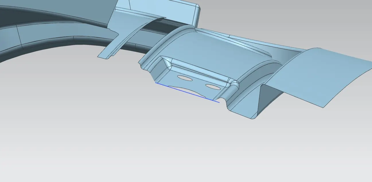
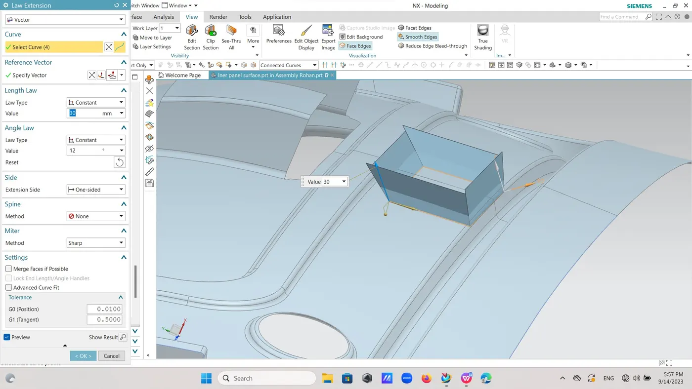
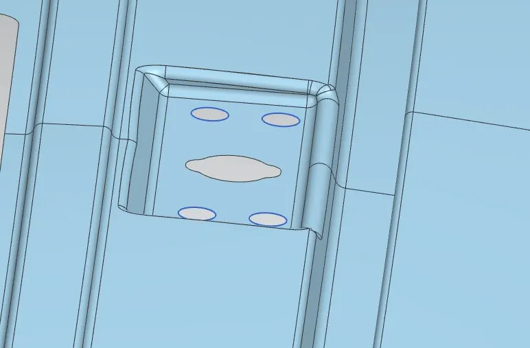
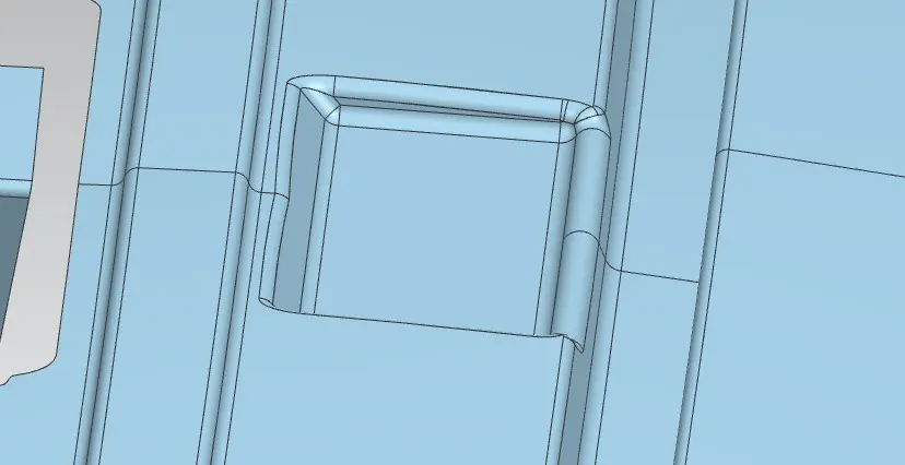
Wiper motor mounting:-As per above took same plane drew a line 5mm offset from surface then used law extension choose symmetry took distance of 30mm and adjust the angle to make it flat surface then used law extension command and extend it along tooling axis by some distance upward then sew two surfaces then trimmed with original surface then used edge blend to blend the edges of that pocket .
Sane as took three point plane drew a sketch to it project it on pocket surface and trimmed it body.
Same as above drew circle drew horizontal line then another line by taking some angle then one tangential line with keeping on point of intersection and inter sect that point with central circle of that pocket.
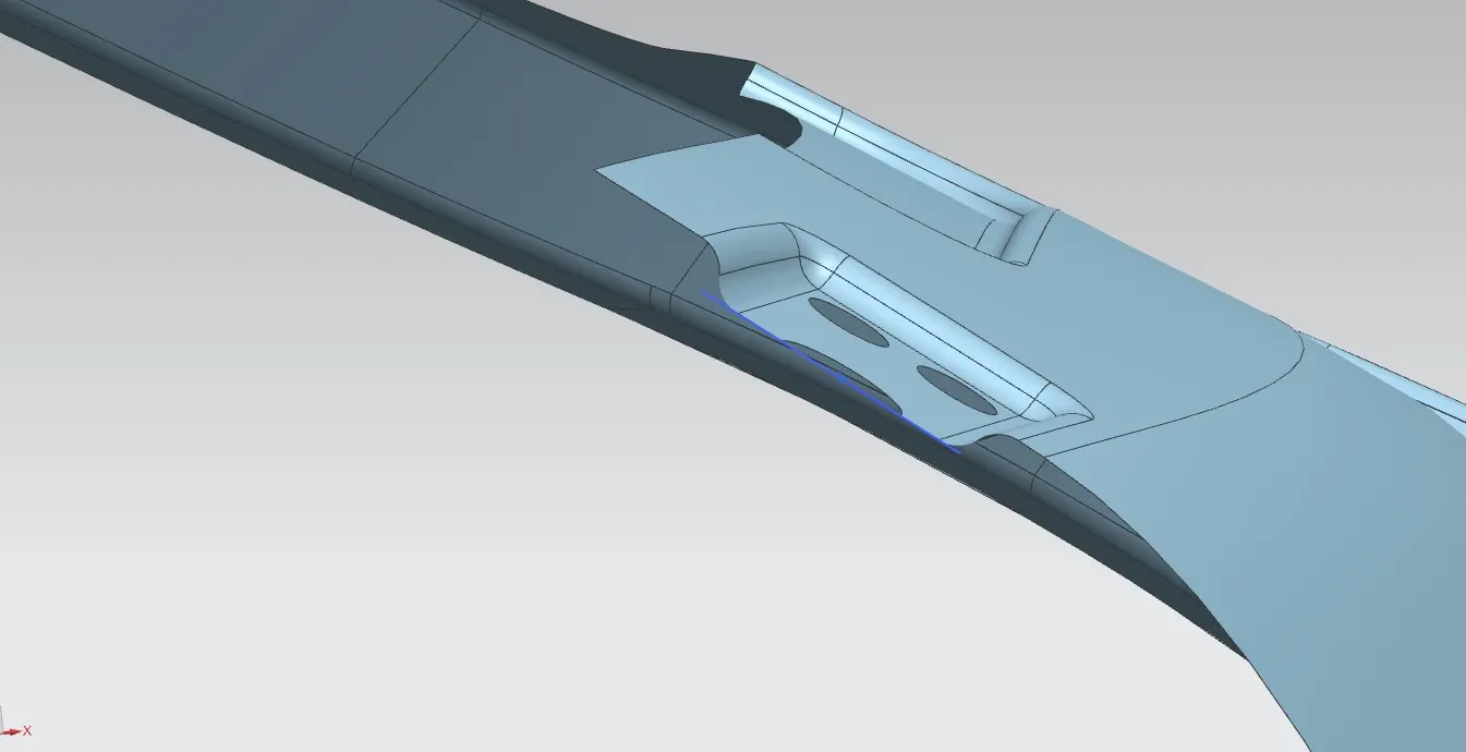
BACK DOOR OUTER UPPER PANEL:-
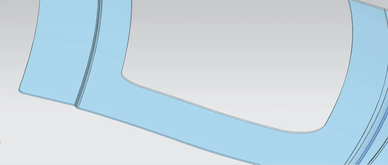
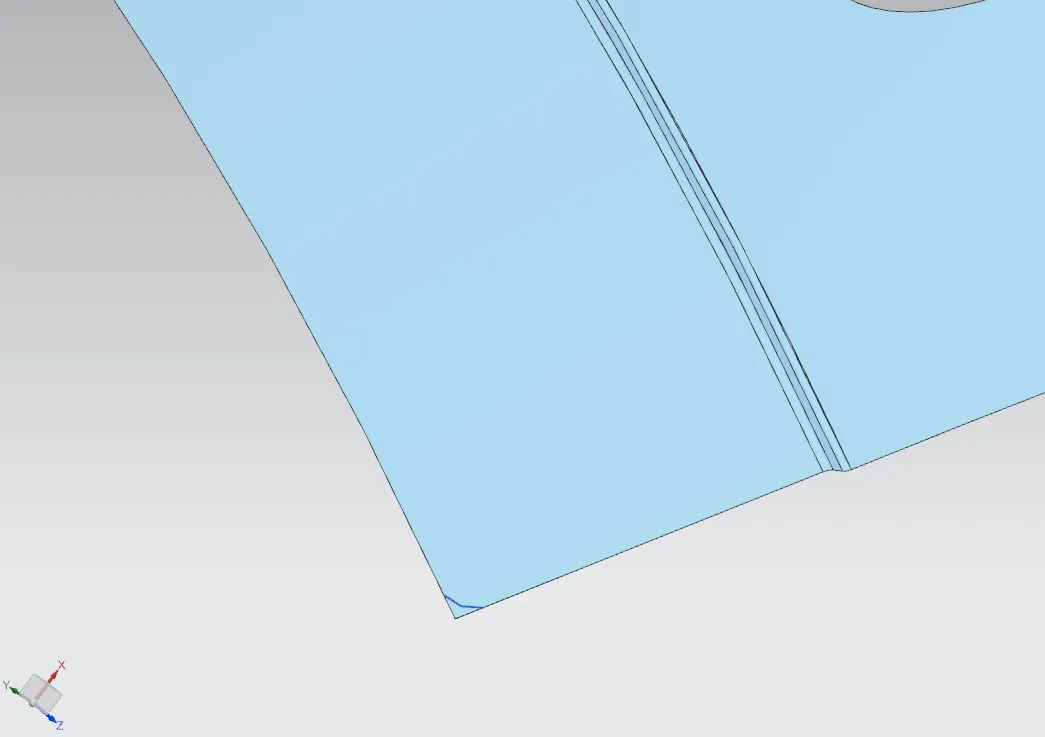
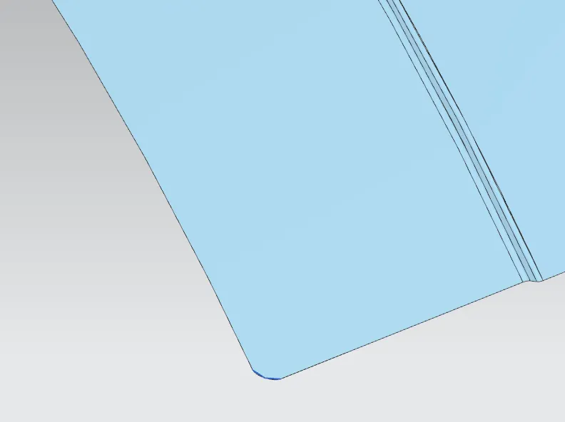
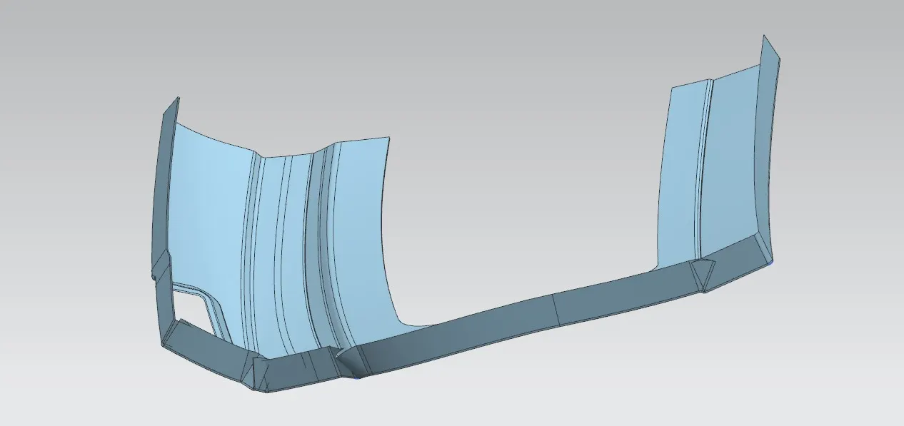
As given linked surface extract surface then to coincide with inner panel trimmed off its corners by 8mm by using bridge curve by length .
Then repaired some irregularities,then offset that surface by distance of 2.65 in downword direction {0.75+0.2+0.75+0.2+0.75}
As outer surface thicken inside and inner surface thicken upper direction also has to keep some clearance of 0.2 mm from both side of inner surface for hemming process.
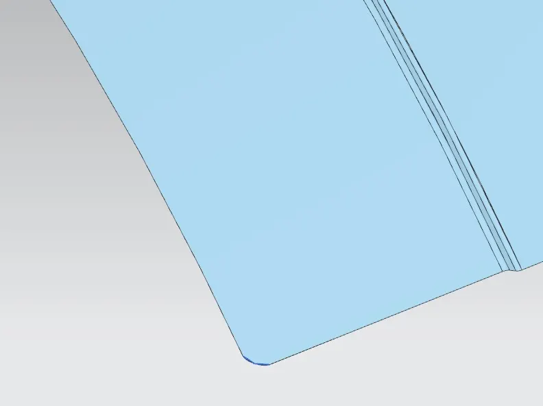
Then offset outer edge of offset surface inside by distance of 8mm for outer region creation by trimming excess surface .like seal falange .
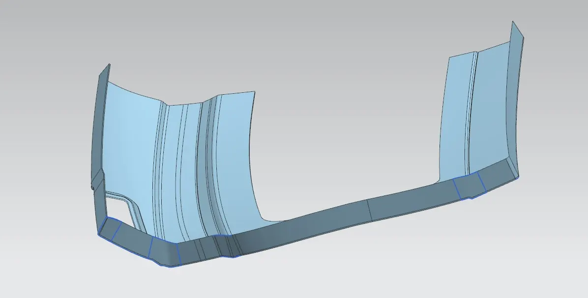
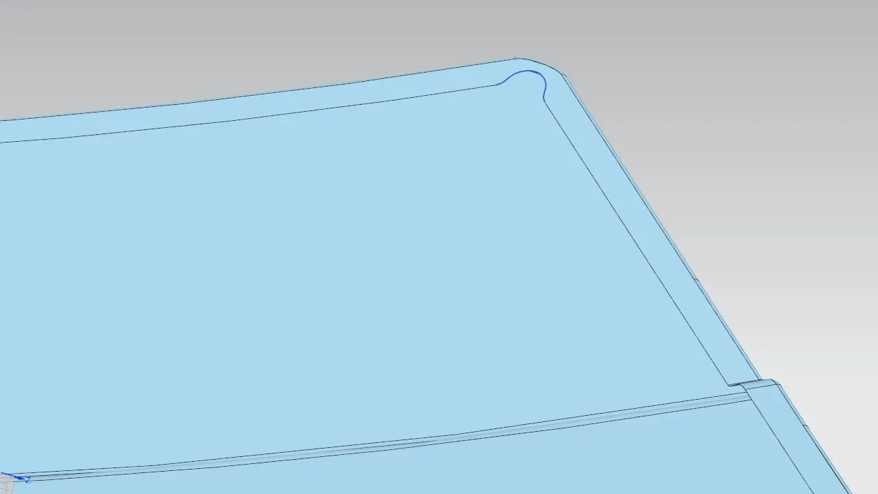
By using three face blend from face blend option use upper surface exterior edge and law extension command direction as tooling axis to words downward until it cut to lower surface.
Then by using three face blend select upper surface arrow direction in downward direction and lower surface direction in upward then mid surface that is law extension inward direction so U shape curvature has created by three face blend .then after creation of this thicken that surface by 0.75mm inward.changed thick entity colour.
Associative copy : Before thicken it final surface edges are extended by 5mm distace then trimmed off excess surface by using mid plane and then go to insert then Associative copy then mirror geometry.
Command:Surface> Offset
Command :Curve>offset curve in face>trimmed surface.
Surface>face blend >three face blend.
Insert side to menu>Associative copy >Mirror Geometry
Surface>thicken
Outer Lower Surface:-
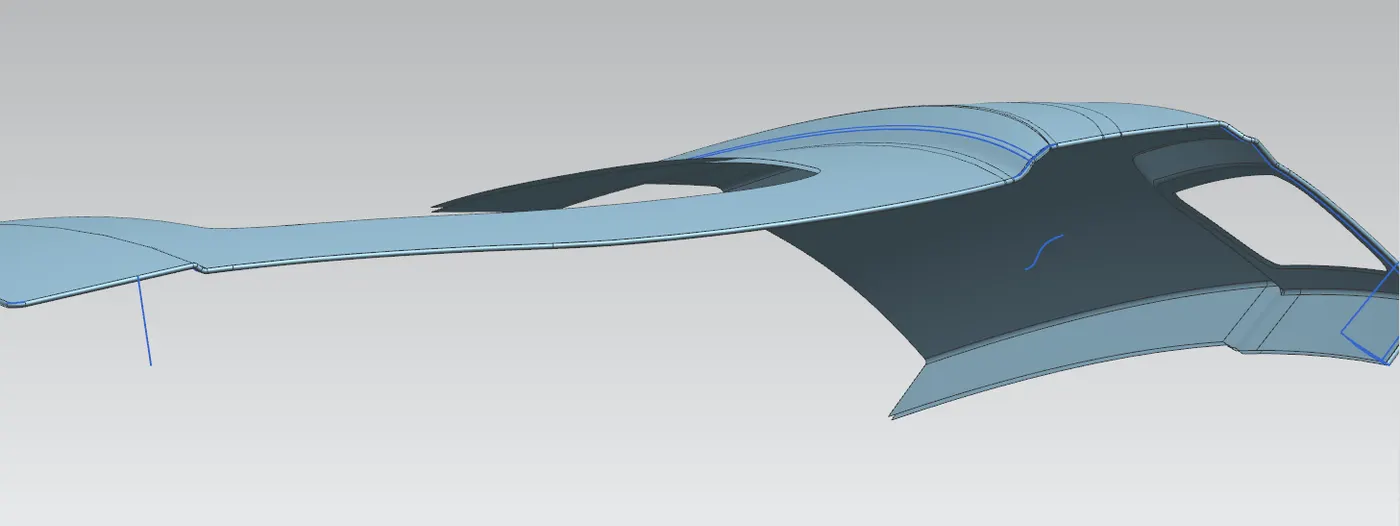
In creation of outer lower surface same as above process has followed but while offset that surface was not able to offset it properly so did it by step wise firstly by some distance and then remaining distance of 2.65mm covered.
Used law extension select outer extreme edge of upper surface for law extension in downward direction with tooling axis as guide.
By selecting outer edge of offset surface go to curve and offset it by distance of 8mm inside and finally trimmed it for seal flange.
Associative copy : Before thicken it final surface edges are extended by 5mm distace then trimmed off excess surface by using mid plane and then go to insert then Associative copy then mirror geometry.
Then by using three face blend create U shape blend.
Then thick that surface by distance of 0.75mm inside.
Command:Surface> Offset
Command :Curve>offset curve in face>trimmed surface.
Surface>face blend >three face blend.
Insert side to menu>Associative copy >Mirror Geometry
Surface>thicken
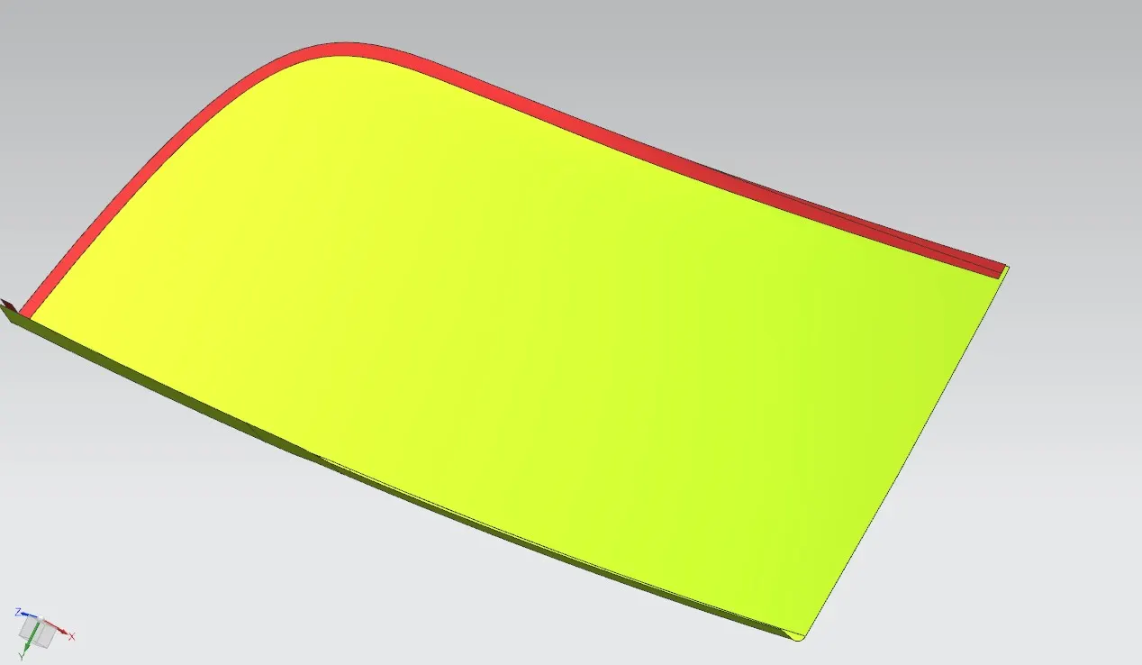
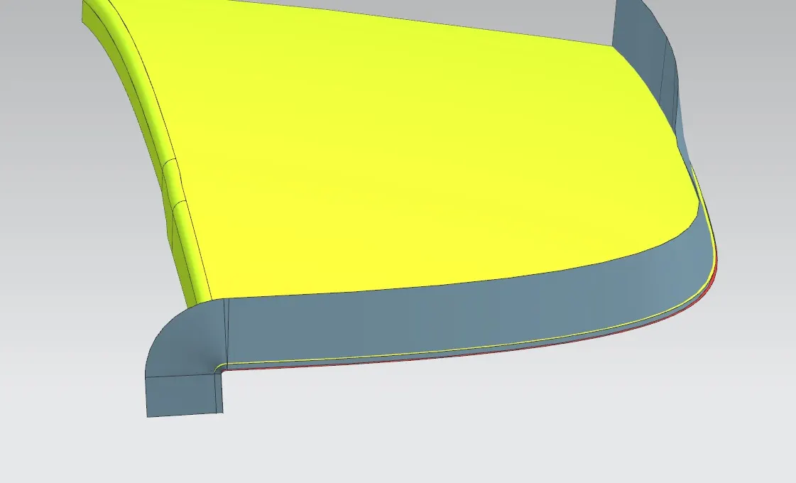
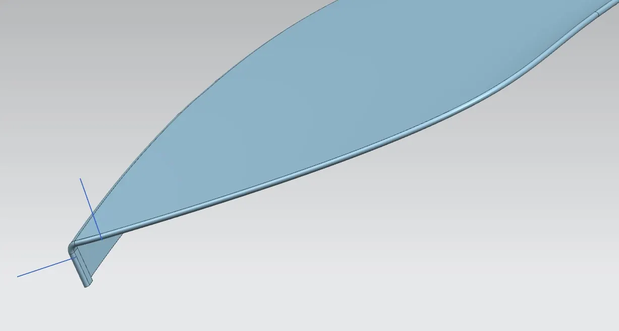
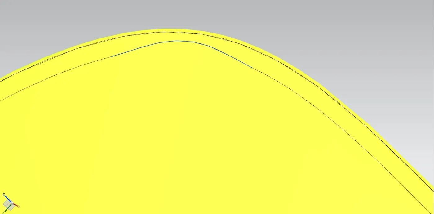
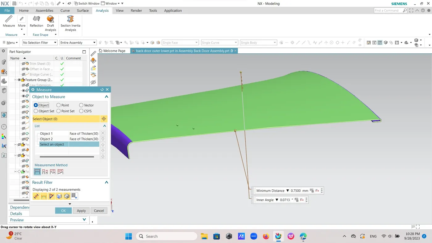
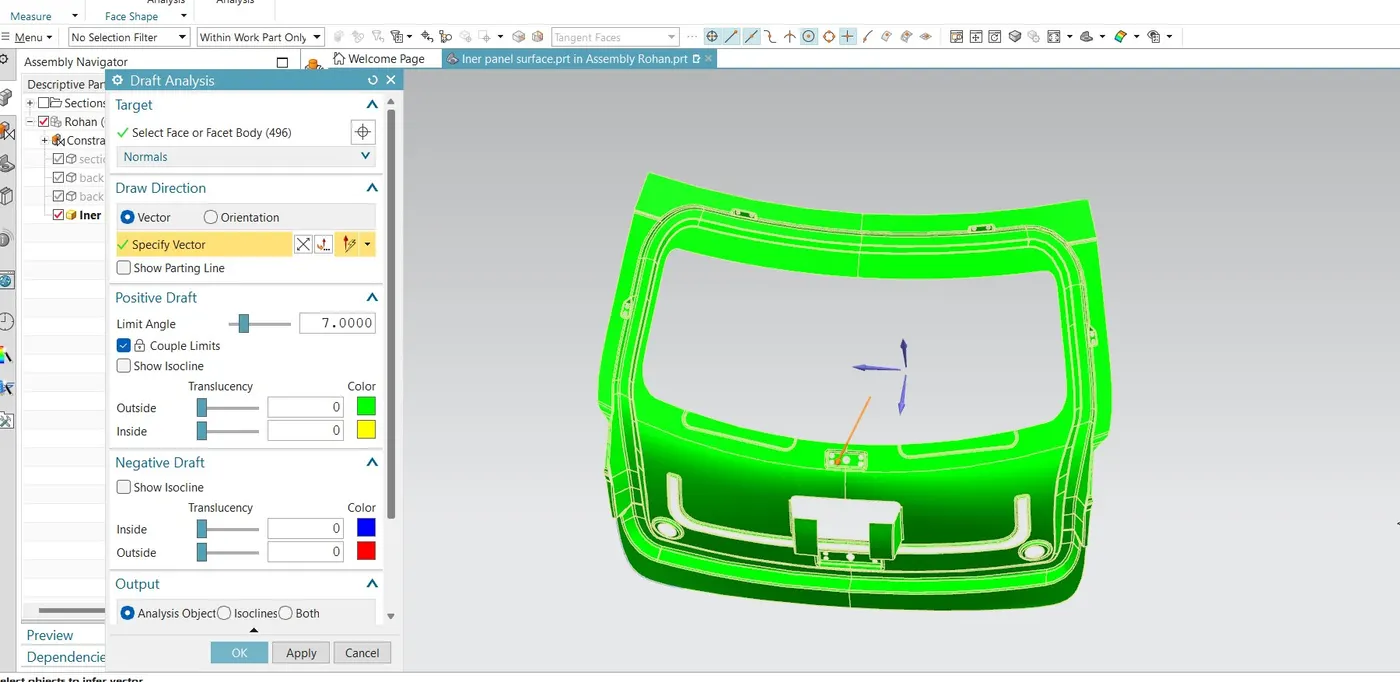
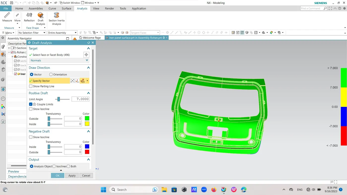
Draft Analysis: Go to draft analysis command {go to search type draft analysis }
Select surface then select tooling axis as vector its clearing for draft analysis where all the portion here showing green in colour
Minimum draft that we can keep is 7deg and maximum can be above that .
We can not keep lower than 7deg because while retracting tooling axis attrition will happen .
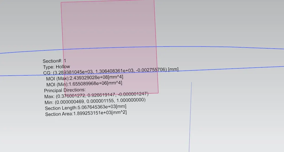
Moment of Inertia :
Took a datum plane on curve then select entire assembly from menu bar then select partition line then go to curve intersection select tangential face and select upper face and lower face and inner face then plane as separation .
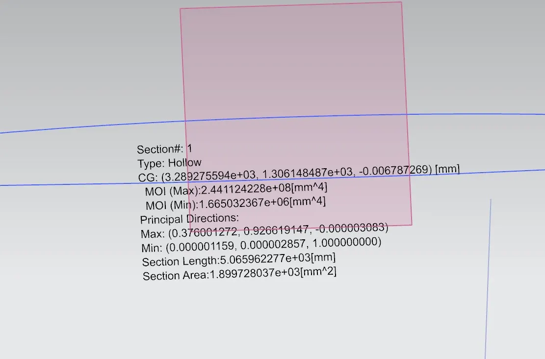
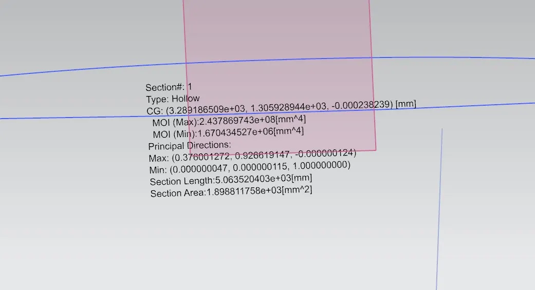
Then hide back door assembly go to sketch select plane as datum plane sketch projection select intersection and project it there then hide intersection then if any irregularity there joint it by spline curve and joint two section then came out of sketch type in search box inertia select it choose that composite curve and calculate MOI by section modulus.then to calculate value of Y we took extreme ends of that curve and half of distance between them and through that calculate inertia. Y=1209.7785/2=604.88925
Then by changing values of curve by offsetting it by 0.5mm checked MOI repeatedly.
Sr NO | Moment of inertia | Inertia |
1 | 1.655089968*10^6 | 273,932,280,317,538.7 |
2 | 1.665032367*10^6 | 10,071,601,797.00355 |
1.66 is greater than 1.65 so it sustain more than previous.
NOTE: MINE FILE IS MORE THAN 20 MB SO COULD NOT UPLOAD IT SO I AM SHEARING MY GOOLE DRIVE LINK WITH YOU.
https://drive.google.com/file/d/1J-68g6qmBW1mxxqu37SFHBDdVmtueV_N/view?usp=drive_link