Design of backdoor
AIM
- To use the provided styling surface to come up with a back door design and to use appropriate design methodologies, and provide the necessary reinforcements and embosses for the back door.
OBJECTIVE
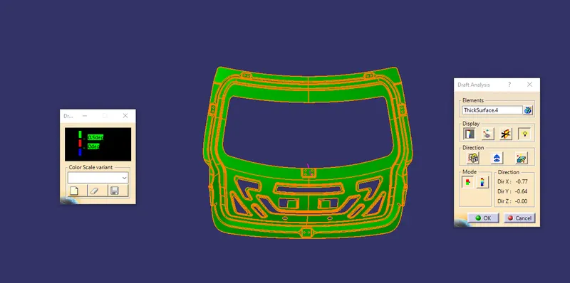
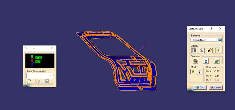
- This projects deals with an explanation of design of a back door, introduction, types, components, design considerations followed in designing and detailed procedure followed in the design of a back door. The styling surface is given for designing the back door. And finally the feature draft analysis is performed for every components to check the manufacturing feasibility.
METHODLOGY
- Design of the back door outer upper panel with the help of the styling surface.
- Dsign of the back door outer lower panel.
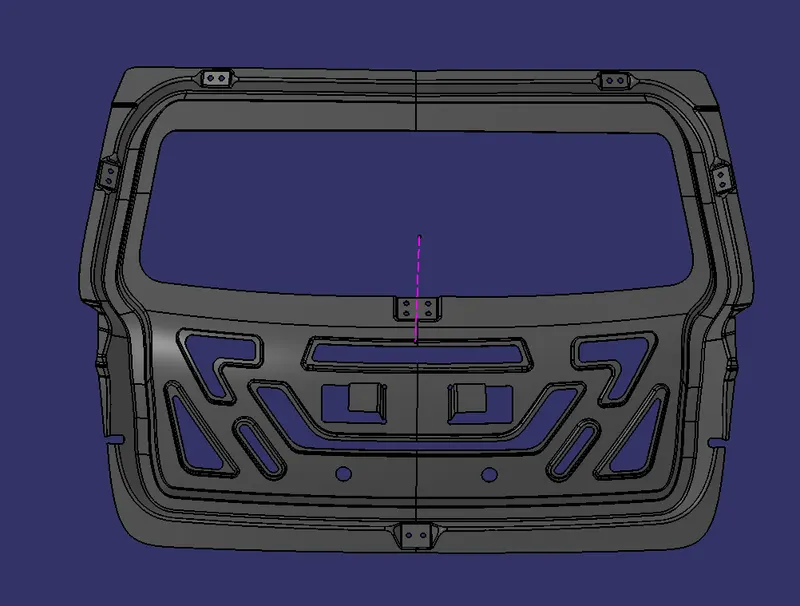
- Creating the inner panel with embosses.
- Creating different mounts (ie., Hinge mount, Gas stay mount, Wiper motor mount & striker mount)
- Creating the reinforcements for each mounts.
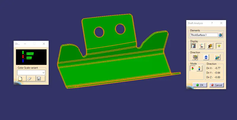
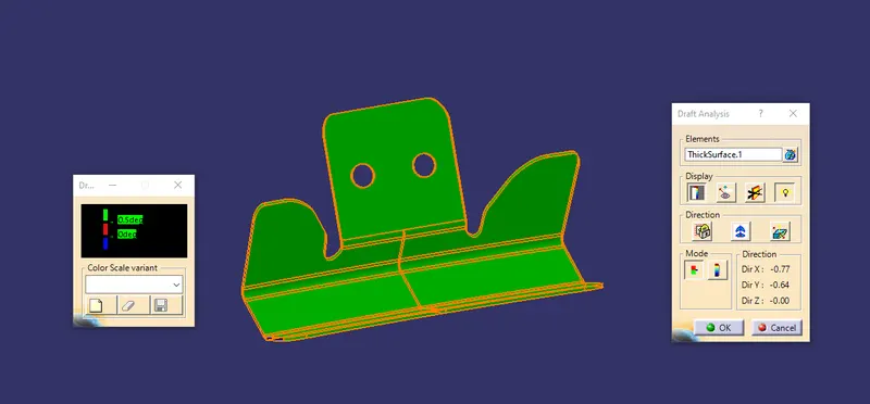
- Performing the feature draft analysis on each components.
INTRODUCTION
- The back door or tailgate is the rear most part of the automobile which opens upwards, downwards, and sideways to give access to the luggage space or seating.In most automobiles, the backdoor opens upwards. It is hinged to the roof and a gas stay support fixed at the body side outer for keeping the backdoor in the open position.The back door is designed considering the safety of the passengers during the rear collision.The material used for making the back door is mostly steel, but now a days, aluminium is used for making panels on the back door.
TYPES OF BACK DOOR
The following are the types of back door considered based on the opening position
- Hatch back or Top mounted door
- Side mounted door
- Bottom mounted door
HATCHBACK DOOR
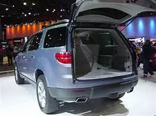
- The hatchback or top mounted doors is used in a station wagon, pickup trunk and some of the spot utility vehicles.Nowadays modern cars use top mounted tailgating system which are both powered and also gas stay supported.These top mounted tailgates provide greater rear visibility compared to side mounted or backdoor which have center pillars in it.
SIDE MOUNTED DOOR
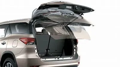
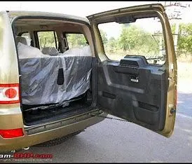
- The side mounted doors are the one which is used in the MPVs, SUVs, pickup truck vehicles.The side mounted doors or barn doors are a lot easier compare to top mounted doors.
- These doors are generally smaller in size and can be easily accessed.These types of doors are more convenient for the goods handlers for long pipe and lengthy components where one door is kept open.They can also save accidental head impacts. It is a lot easier to load and unload items in the side mounted doors.
BOTTOM MOUNTED DOOR
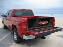
- These back doors are usually used in olden days and now, only the delivery trucks and vans are having the bottom mounted doors at rears.
COMPONENTS OF BACK DOOR
- Outer panel
- Inner panel
- Hinge reinforcements
- Gas stay reinforcements
- Wiper motor reinforcement
- Striker reinforcement
OUTER PANEL
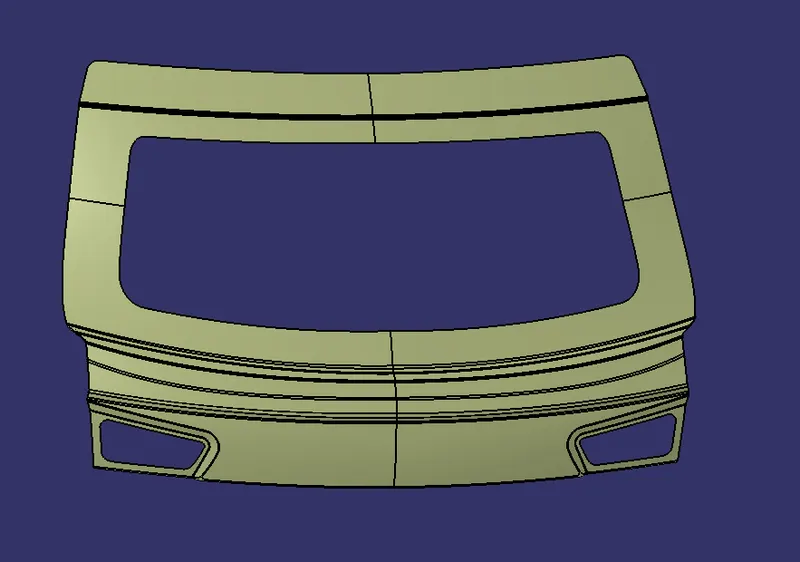
- This panel acts as a styling surface, which is pre-designed by the styling team. Both outer upper panel and outer lower panel are joined by spot welding, which together makes a complete outer panel.The outer panel and the inner panel are joined with the process of hemming along the sides. Mastic Sealants are also used to join them together. Corner reliefs are provided at the edges of the outer panel for the hemming process.
INNER PANEL
- The inner panel is a important component in the backdoor, which helps in strengthening the backdoor assembly. Reinforcements and embosses are attached to the inner panel to strengthen the mounting region of the panel.
REINFORCEMENTS
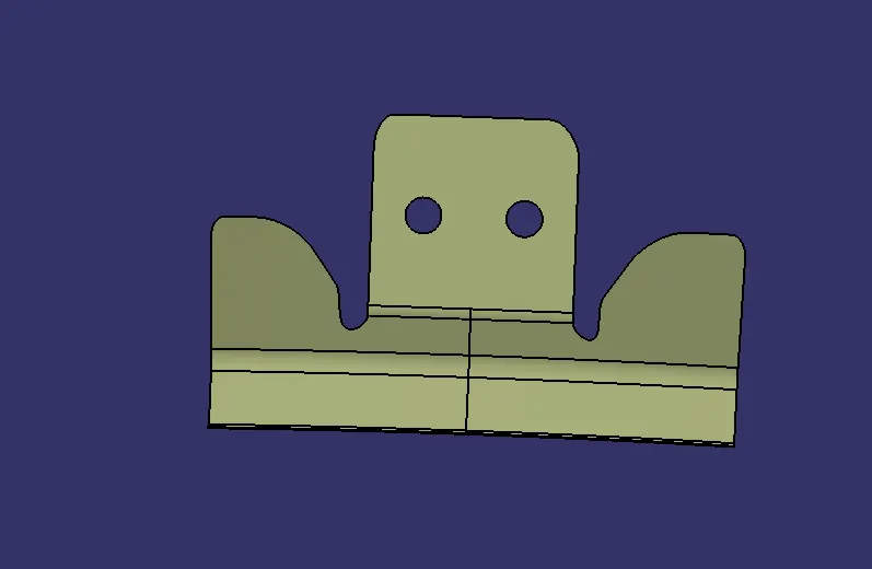
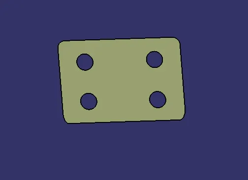
- The reinforcements are provided to give sufficient structural strength to the beam or to the panel.The reinforcement are provided at the mounting regions( ie., hinge mounting, gas stay mounting, wiper motore mounting and the striker mounting).
DESIGN CONSIDERATIONS
The following are the main factors considering while designing the back door,
- Rear visibility
- Rear crash regulation & requirement
- Sealing and its functions
- Joining techniques
- Manufacturing techniques
- Gap and Flushness
- Opening & Closing angle
VISIBILITY (REAR)
- It depends on the window opening and their relative position to the occupants. If occupant is placed close to wind screen the forward visibility is considerably improved but comfortable entry is adversely affected as dimension between pillar and seat is decreased requiring suitable shaping of the door, if possible. Downward visibility can be improved by positioning the driver as high as possible in retaliation to the lower edge of wind screen. Rear visibility is achieved by increase in glass area required to maintain rear view vertical angle with back window.
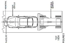
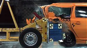
REAR CRASH REGULATION
- Since, the rear region of the car is a crumble zone area, that region should be made with high tensile strength material so that it can withstand the crash or will reduce the impact of the accident on the rear side.
SEALING
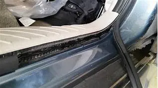
- This acts as a sealing function to avoid the dust and water entering inside the car. The sealing flange is provided where ever other strips come in contact.
- There are two types of strips used as the sealing. yhey are wheather strip and the dynamic strip. the wheather strip is used to prevent the sticky mud or water particles entering into the car.
- And the dynamic strip is used when the load is applied the material defprms and other strips will come and sit on the dynamic strip.
JOINING TECHNIQUES
The following are the joining techniques used in back door ,
- Hemming
- Spot Welding
- Mastic sealant
HEMMING OPERATION
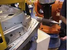
- This process is a forming operation in which the edges of the sheet are folded or folded over another part in order to achieve a tight fit. Hemming is a technology used in the automotive industry to join inner and outer closure panels together (hoods, doors, tailgates, etc.). It is the process of bending/folding the flange of the outer panel over the inner one. The accuracy of the operation significantly affects the appearance of the car’s outer surfaces and is therefore a critical factor in the final quality of a finished vehicle.
- In roller hemming process, a robot guides a small roller across the flange to fold a sheet onto itself or onto another sheet. The process is oriented to low volume automotive applications, providing a distinct advantage in manufacturing closures and sub assemblies with developed flanges.
- The hem glue that is applied in the attachment of inner and outer panel during the hemming process.The gap of 0.2mm is maintained for this glue.
SPOT WELDING
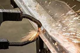
- This operation is a type of resistance welding. In this spot welding the two metals are kept in one over the other with zero clearence between them and then welded together with the supply of heat resistance at the two electrodes.
- This is done betwnn the back door outer upper and outer lower panels.
MASTIC SEALANTS
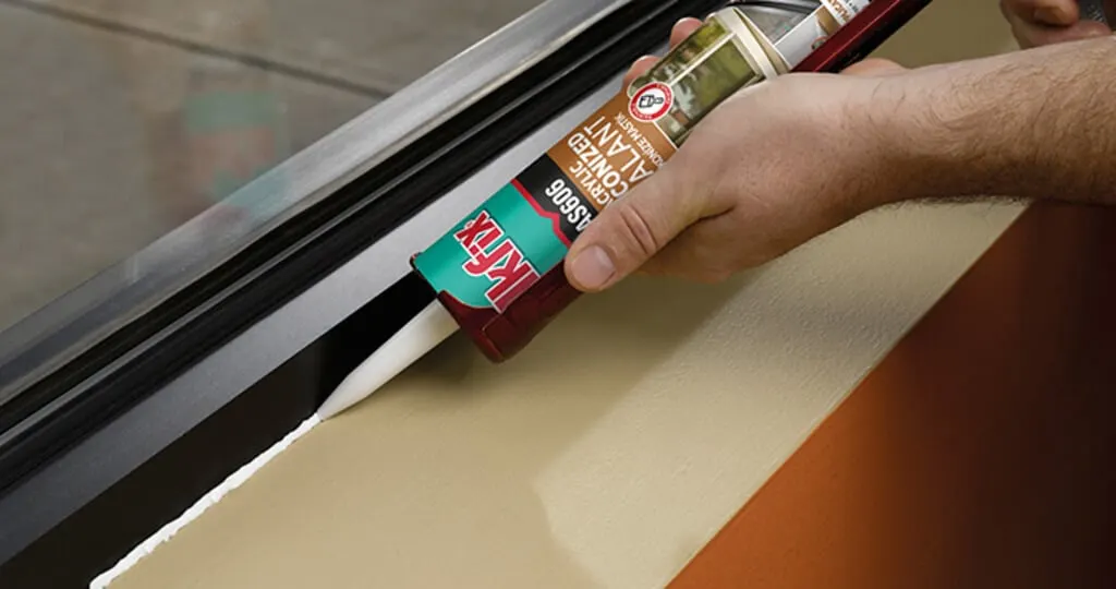
- The mastic sealant can act as a protecting layer between elements. The features of this sealant and how it works makes it different from the others. It forms a smooth exterior which makes the surface flexible while maintaining a hard plastic beneath the surface.
- To improve NVH (noise, vibrations, harshness), mastic sealants were provided on the inner panel to attach with outer panel. Here mastic points on the inner panel plays a major role to avoid Noise and Vibration into the cabin. NVH is measured by the instruments, namely microphones, accelerometer and force gauges, or load cells. Component and sub-assembly NVH tests are most commonly performed using a vibration shaker while entire vehicles usually on the test track or road simulator test-beds.
MANUFACTURING TECHNIQUES
EMBOSSING
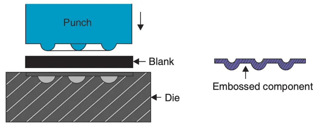
- Embossing is a stamping process for producing raised or sunken designs or relief in sheetmetal. This process can be made by means of matched male and female roller dies, or by- passing sheet or a strip of metal between rolls of the desired pattern, theoretically with no change in metal thickness, or by passing sheet or a strip of metal between rolls of the desired pattern.
- Metal sheet is drawn through the male and female roller dies producing a pattern or design on the metal sheet. Depending on the roller dies used, different patterns can be produced on the metal sheet.
- Emboss should be in 7 degree to 25 degree inclined in angle and it should not be in 90 degree angle, why because when we do stamping in manufacturing the stamping tool fits the sheet metal hence it will not come out of that sheet metal.
HEMMING
- This is a common metalworking process mainly carried out to reinforce an edge, hide burrs or just improve the overall appearance of sheet metal parts. When hemming is carried out in a way that a joint between two sheet metal parts is created, it is called seaming but more on that later.
- Hemming in sheet metal operations refers to the bending of a sheet metal edge onto itself. It is very similar to edge stitching in clothes. Similar to how an edge stitch strengthens the edge and makes it more durable, a hem imparts strength to the metal edge and improves its appearance. The edge of one part may also be folded onto another part to create a joint.
DEEP DRAWING
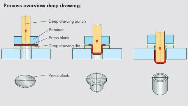
- The deep drawing process is an effective method of manufacturing of Sheet like components to the products. The process involves a punch with a round comer and a die with a large radius. The punch-die clearance is slightly larger than the thickness of the sheet metal to be deep drawn. As the load applied through the punch, the sheet metal is forced to flow radially and sink into the die cavity to form a cup. The process is best suitable for complex shaped problems. The deformation is not even throughout of the blank. Due to the bi-axial compressive stresses, the flange gets thicker while, the vertical wall gets thinner, due to the uni-axial tension, failure is expected at the location of maximum thinning.
STAMPING
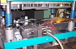
- Stamping is a cold-forming process that makes use of dies and stamping presses to transform sheet metal into different shapes. Pieces of flat sheet metal, typically referred to as blanks, is fed into a sheet metal stamping press that uses a tool and die surface to form the metal into a new shape.
GAP & FLUSHNESS
- Gap is the distance between the two or more surfaces.
- Flushness is the distance from the two surfaces. The flushness decreases from front to rear of the an automobile.
OPENING & CLOSING ANGLE
- The opening and closing factor is very important factor in back door design. While accessing the boot space compartment, the back door will be open at desirable angle. This angle is decided based on the average height of the person in that region.
PROCEDURE
BACK DOOR OUTER UPPER PANEL
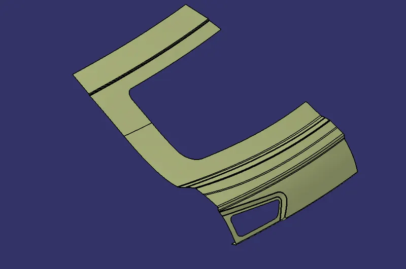
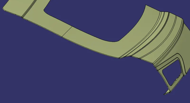
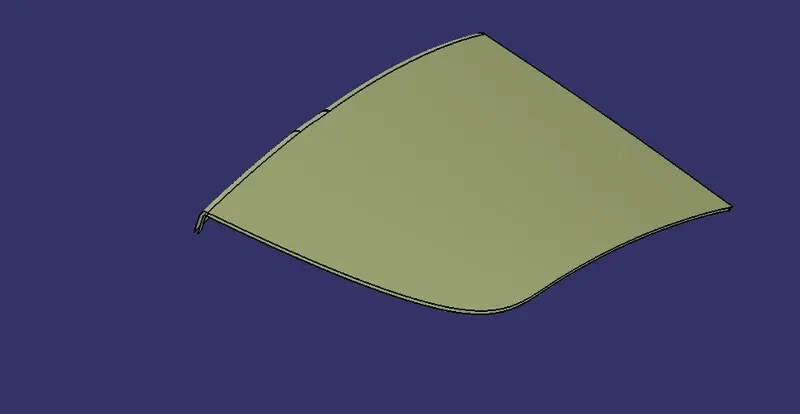
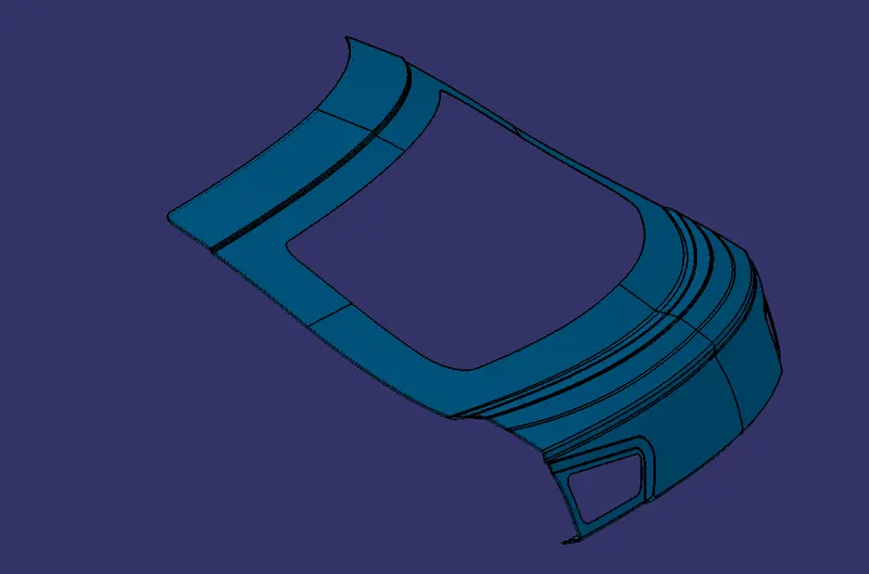
- The styling surface was extracted and it was repaired before creating the outer upper panel.
- The tools used in repairing the surfaces was sweep, parallel curve, split, multi section, join and boundary.
- Then the repaired upper surface is used as the back door outer upper panel.
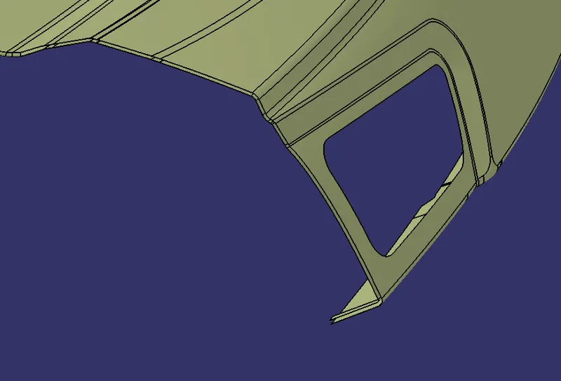
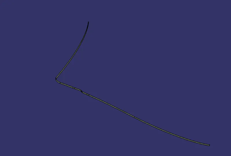
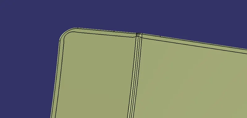
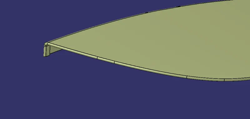
- After that for hemming, the outer surface is offset to the distance 2.65 mm downwards and the hem flange was 7 mm was parallel curved inside and splited.
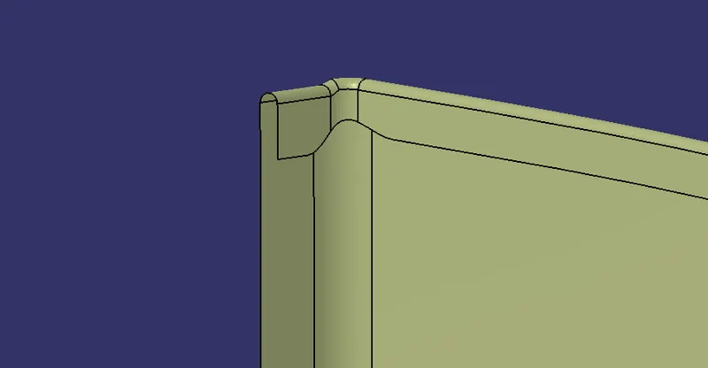
- Then outer surface boundary was created and sweeped with reference to the surface and then tritangent fillet was given and hemming was done.
- Reliefs were created to the bended regions on the outer upper surface.
BACK DOOR OUTER LOWER PANEL
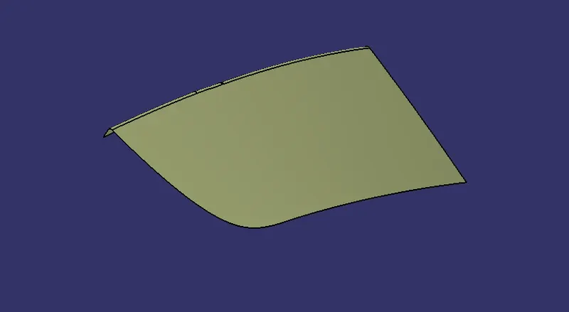
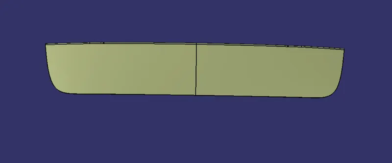
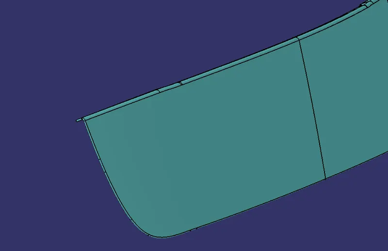
- Use the repaired outer surface for the lower panel. For that extract and use boundary to check the connectivity.
- After that for hemming, offset the lower panel surface to the distance of 2.65 mm in download direction.
- Then split the Offsetted surface by taking the parallel curve of the boundary of that surface to a distance of 7mm.
- After splitting, create a boundary on the lower panel and sweep with reference to the surface and apply tritangent fillet to the three surfaces.
BACK DOOR INNER PANEL
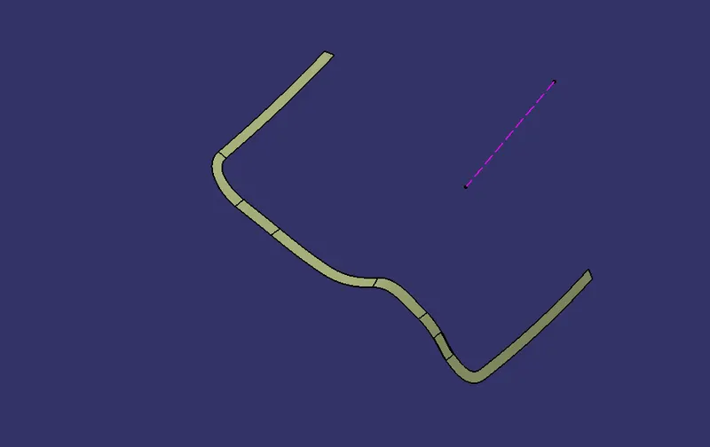
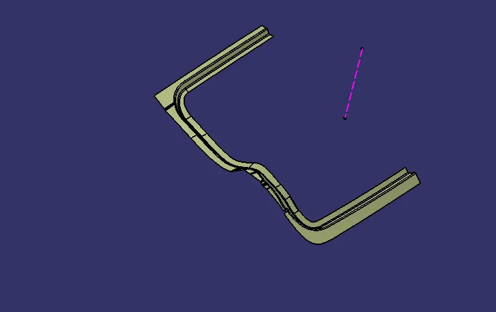
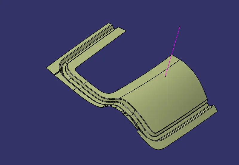
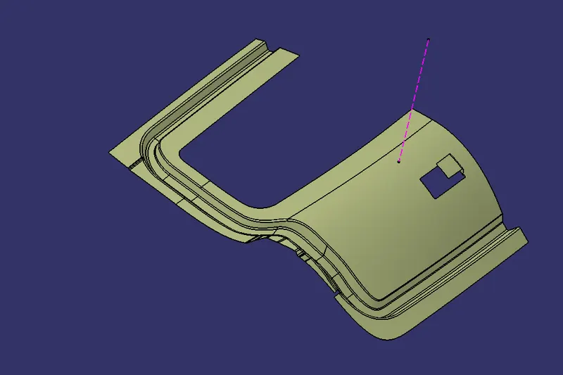
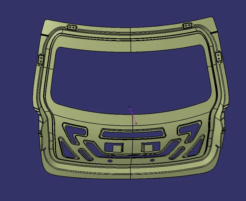
- For creating the inner panel, first extract the outer upper surface and offset it to the distance of 30mm.
- Create the sealing flange by extracting and offsetting the outer panels.
- The tools used to create the sealing flange are parallel curve, spline, split, offset, join, and extract.
- After creating the sealing flange, the cover portion is made by the tools sweep, extrapolate, split, parallel curve and multi section.
- Then create the embosses on the surface to provide the sufficient strength.
- Then extrapolate the surface to 5mm and split that with the help of center data plane.
- Use symmetry on that surface to mirror it.
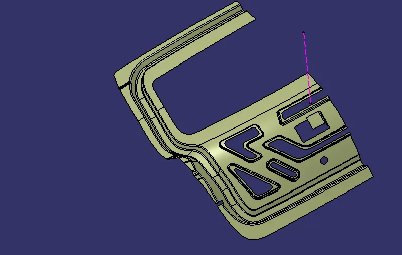
The following mount creations should be done along with the inner panel.
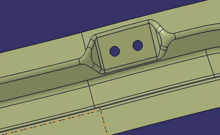
HINGE MOUNT
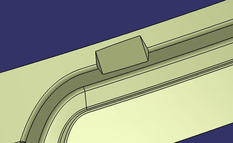
- Create a plane by normal to curve in the top of the sealing flange.
- Insert a sketch with that plane and draw a line accordingly for hinge mount flat surface.
- Then sweep that line with the draft direction and adjust the angle to our requirement.
- Then, sweep the two edges separately with required angle.
- Join the three sweeps and use split feature with the inner panel.
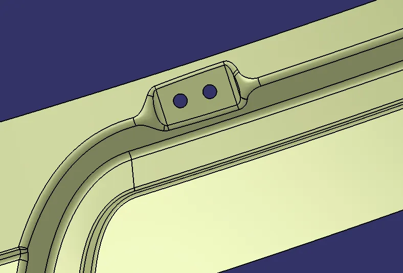
- Create holes on the flat surface of diameter 10 mm. Then split it using split feature.
- Apply edge fillet on the sharp edges on the mount.
- Finally mirror it while mirrorig the inner panel.
GAS STAY MOUNT
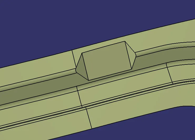
- Create the gas stay mount as same as the hinge mount procedure.
- The gas stay mount should be created on the side of the sealing flange.
- Then use symmentry on it while mirrioring the inner pannel.
WIPER MOTOR MOUNT
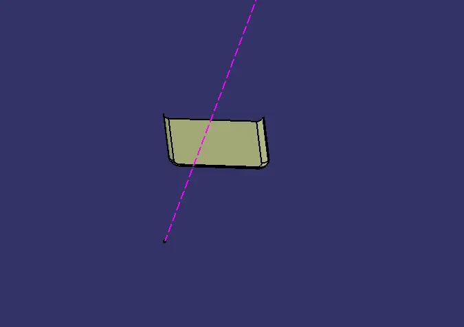
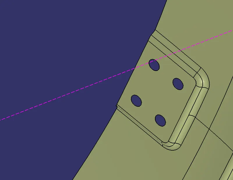
- Create a plane by using the tangent to surface at the lower porsion of the windsheild ie., at the center.
- Create a sketch for the wiper motor mount on that plane.
- Now, sweep the sketch with draft direction in downwards direction with angle of 10 - 15 degrees.
- Offset the plane to around 6.5 mm and draw a line on that palne and use extrude or sweep on the line to get the flat surface.
- Apply shape fillet to the two surfaces with an fillet radius of 3 -3.75 mm.
- Create holes on the flat surface and split those using split feature.
STRIKER MOUNT
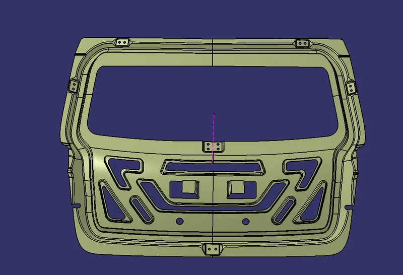
- Create points on the holes of the hinge mount on both sides.
- Draw a line with respect to those two points by point to point.
- Create a plane at the center of the line useing between option.
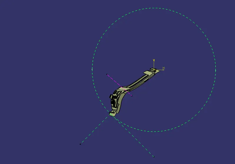
- Create a sketch on that plane and draw a circle which passes the lower surface ie., the sealing flange at the center of the back door.
- Draw a line tangent to the circle and draw a line perpendicular to the tangential line, ie. 90 degrees.
- Now, create a point where the circle passes the inner panel sealing flange. There create a plane and draw a line and sweep it with respect to the draft direction and sweep the edges also.
- Join all the three sweeps and use split feature and use edge fillets on the sharp corners.
- Create holes on the surface and split the using split feature.
REINFORCEMENTS
- The reinforcements are created to provide the structural strength to particular regions where the mounts are created.
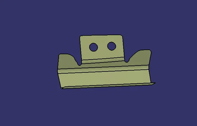
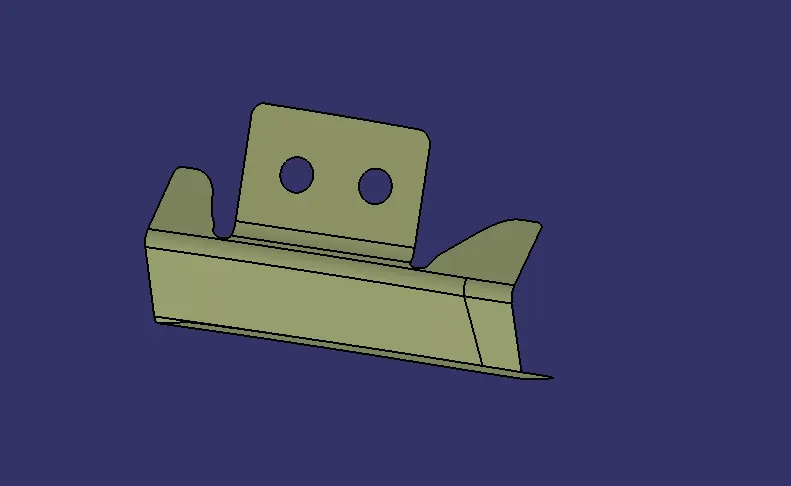
- For creating the reinforcements first extract the surfaces of the each mounts seperately and then create planes on both side of the extracted surfaces to split them.
- Then use create points, spline and split features to provide the curved edges and reliefs on the reinforcements.
HINGE REINFORCEMENT
GAS STAY REINFORCEMENT
STRIKER REINFORCEMENT
WIPER MOTOR REINFORCEMENT
THICKENED SURFACE
- The surfaces which we are created using generative shape design is thickend in the part design using the thick surface feature.
- The thickness given for each componets except the reinforcements are 0.75 mm.
- For reinforcements the thickness used was 2.5 mm.
OUTER UPPER PANEL
OUTER LOWER PANEL
INNER PANEL
HINGE MOUNT REINFORCEMENT
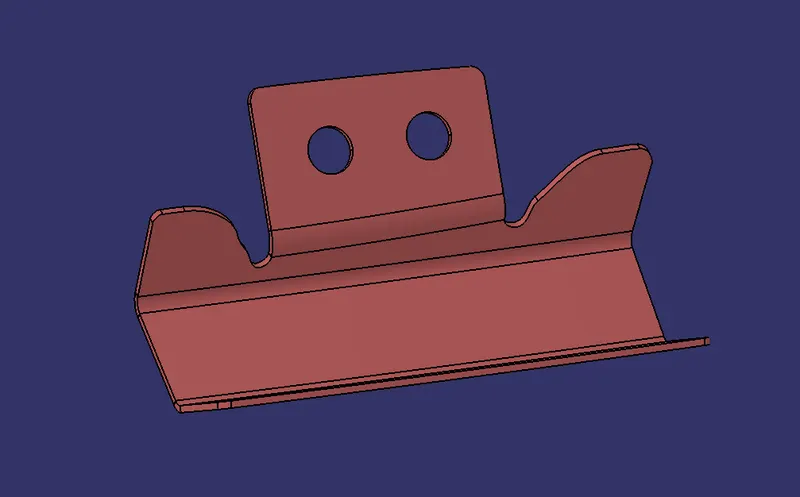
STRIKER MOUNT REINFORCEMENT
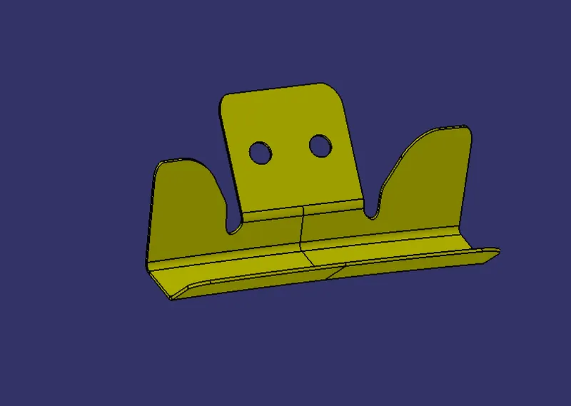
WIPER MOTOR MOUNT REINGORCEMENT
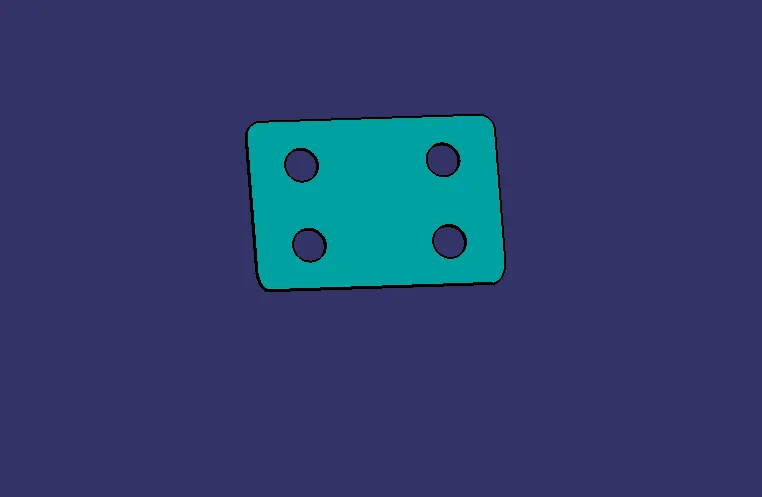
PERFORMING FEATURE DRAFT ANALYSIS
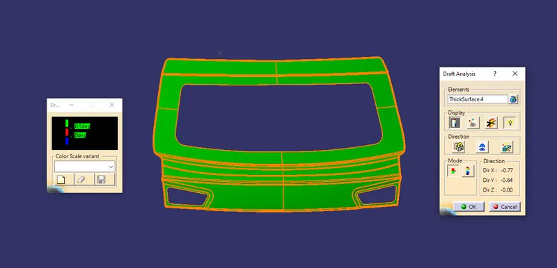
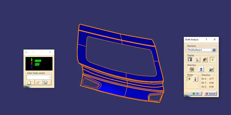
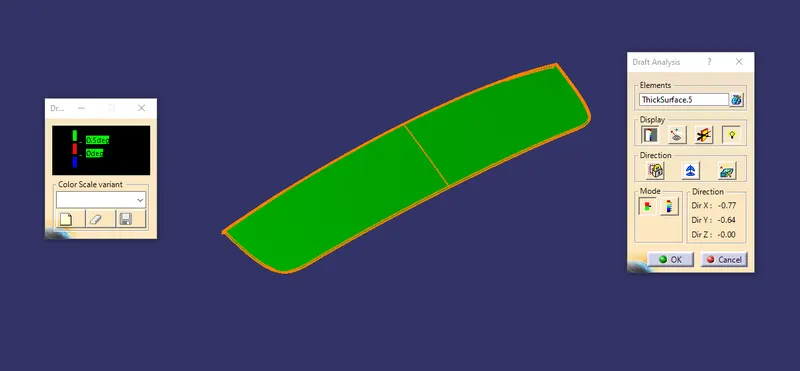
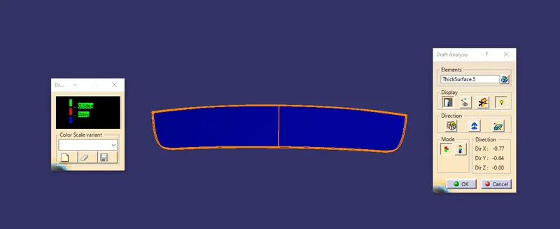
- The draft analysis was performed on each components to check the manufacturing feasibility.
OUTER UPPER PANEL
OUTER LOWER PANEL
INNER PANEL
REINFORCEMENTS
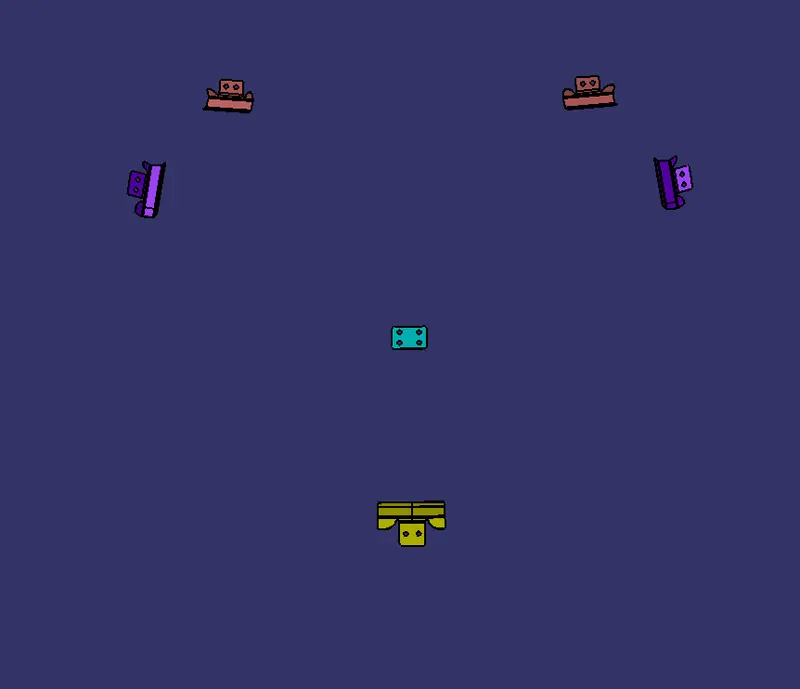
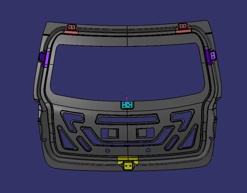
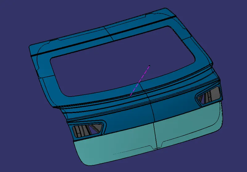
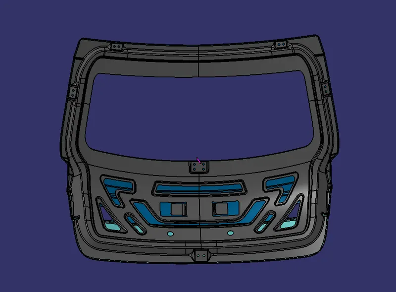
ASSEMBLY
CONCLUSION
- Thus the back door of a automotive vehicle is designed by the given styling surface.Along with that the recinforcements and embosses were also created.
- Finally the draft analysis were performed to check the manufacturing feasibility.