Design of backdoor
Aim: To create the Design of the back door with the Inner and Outer panel and its reinforcement.
Software used: CATIA V5-6R2020.
Objective:
Components to create are given below,
- Upper Outer panel
- Lower Outer panel
- Inner panel
- Hinge reinforcement (Left and Right)
- Gas stay reinforcement (Left and Right)
- Latch reinforcement
Introduction:
The back door is fixed on the rear end of the car which is also called Tailgate and Trunk. It is used to cover the luggage compartment. The back door is hinged at the top of the car body or roof.
If the door is hinged at the top it is termed a hatch and is used on a Hatchback.
It consists of an inner panel and an Outer panel of the back door with reinforcements, the inner panel is made of Steel and the upper panel is made up of Aluminium.
Procedure:
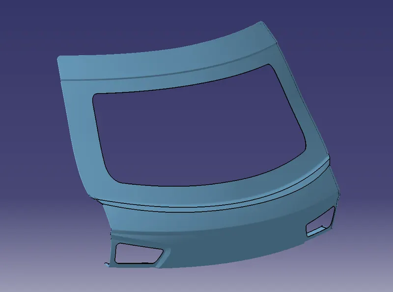
Checking the geometry and creating an Upper outer panel:
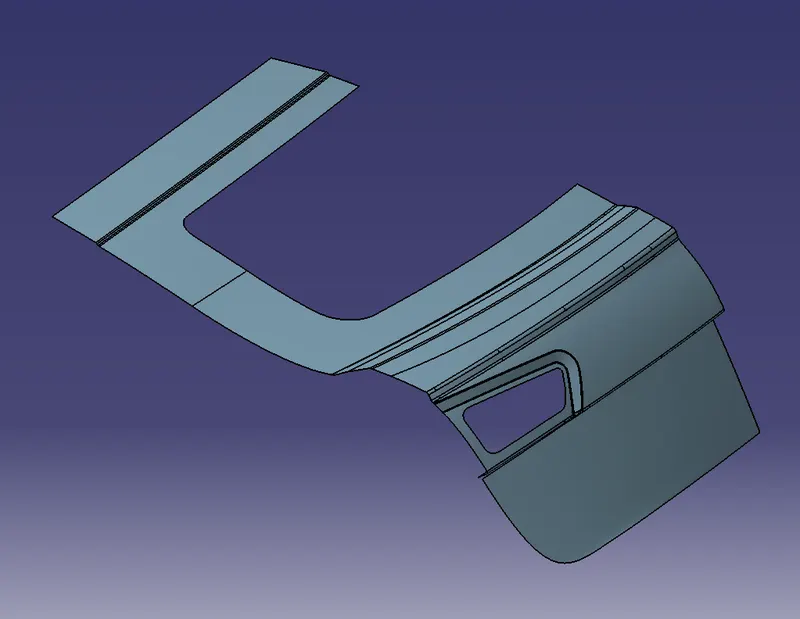
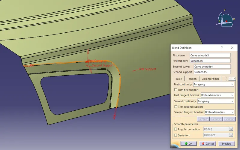
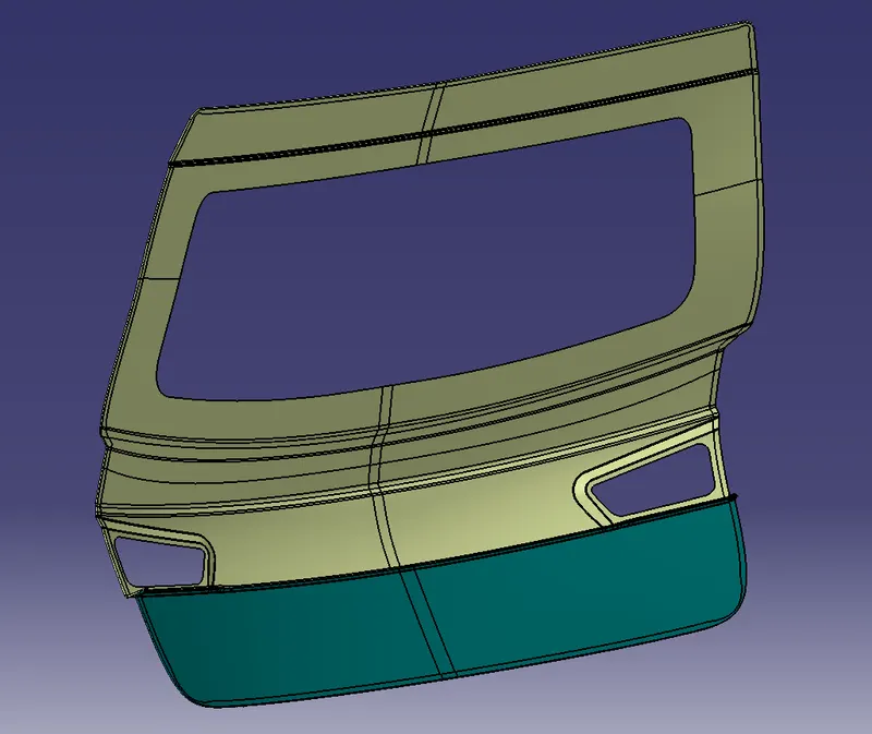
The given Class A styling surface of the Back Door has irregularities and is unable to join, so I have fixed it by removing the fillets and using Multi-section surfaces and Blend operations.
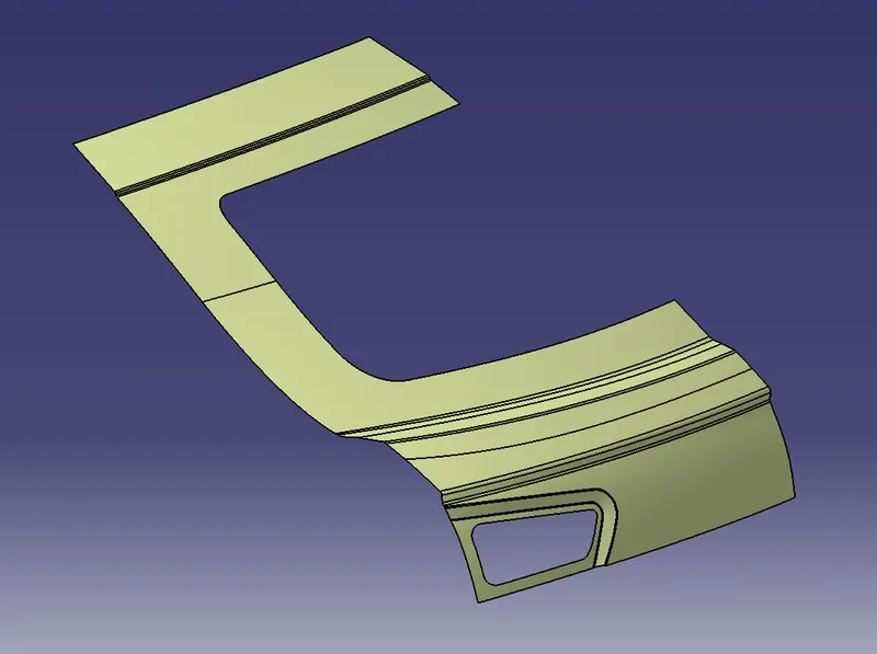
Especially the Tail Lamp Area surface is first extrapolated, trimmed and then given fillets.
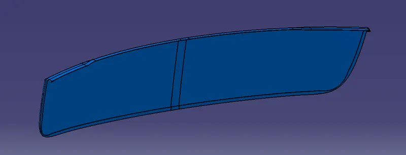
Creating the Lower Outer panel:
The outer panel has a lower and upper panel with different parts and it is joined by spot welding from the inner side.
The lower flange of the upper panel of the outer panel is extracted to join it with the lower panel to join it.
I have extrapolated the lower panel surface and given a face fillet of 4mm with the extracted surface.
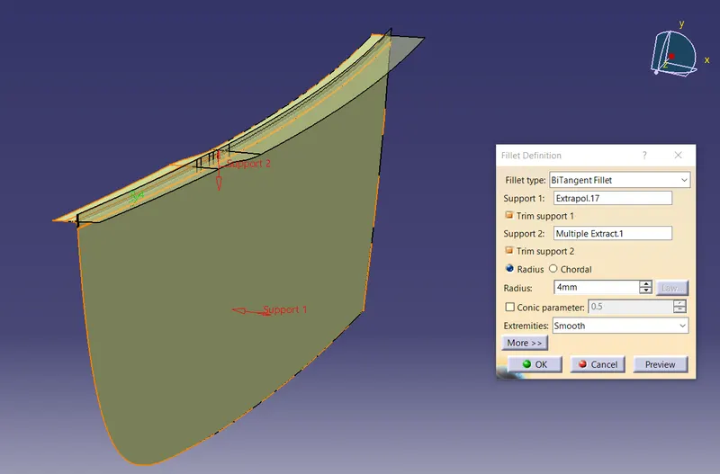
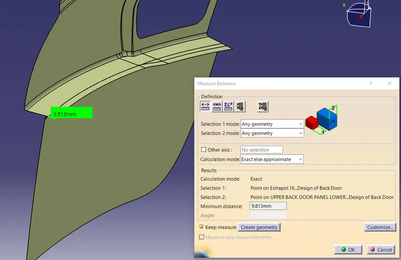
Now I need to create a hemming region on both the upper and lower panel.
Hemming process:
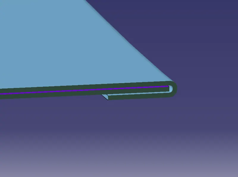
Hemming is a forming operation in which the edges of the sheet are folded or folded over another part in order to achieve a tight fit. Normally hemming operations are used to connect parts together, to improve the appearance of a part, and to reinforce part edges.
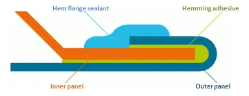 Applications" />
Hemming is a sheet metal forming process in which sheets are joined by bending it usually to 180°. Automotive body panels and automotive parts such as deck-lids, trunk-lids, doors, hoods, and tailgates are formed by the hemming process.
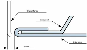
To create the hemming, first, we need to extract the surface and offset it up to 2.65mm (Thickness of outer panel is 0.75mm and Thickness of inner panel is 0.75mm, Gap between the inner panel and Outer panel is 0.2mm, Hemming area bend region is 0.75mm and the gap between them is 0.2mm)
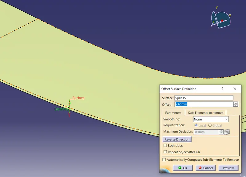
Then used a parallel curve on an offset surface of 10mm
After that, split it with the curve and use the connect curve on the end of the surface of 2mm tangency.
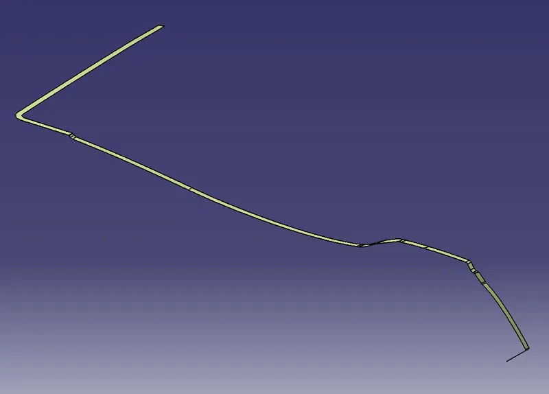
Using sweep command with two guide curves by providing the profile of the connect curve.
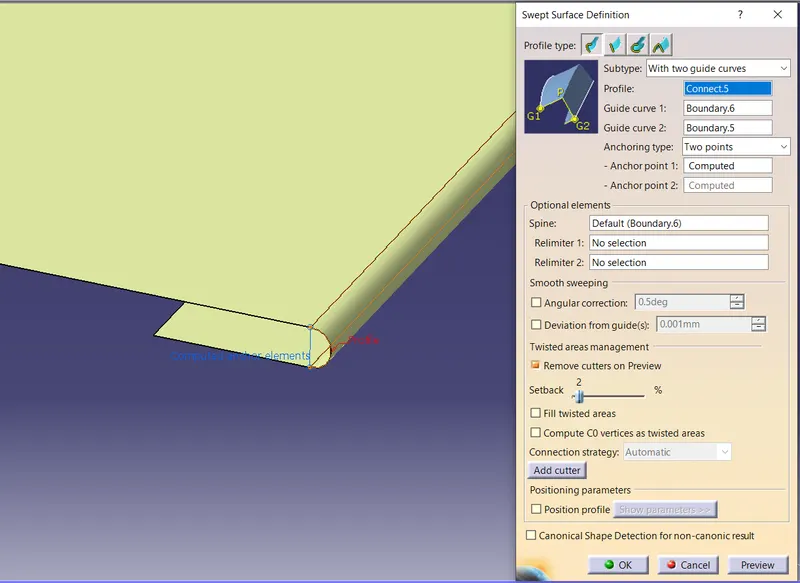
Note: While creating hemming since there are lots of surface irregularities and discontinuity, I have improved the surface where it causes errors while thickening.
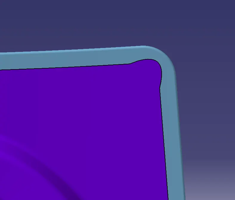
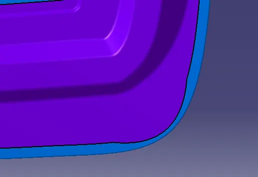
Here I have to give corner reliefs on sharp corners by creating the sketch and splitting it with the surface.
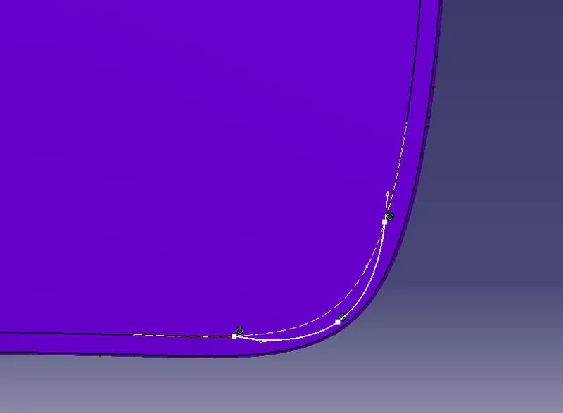
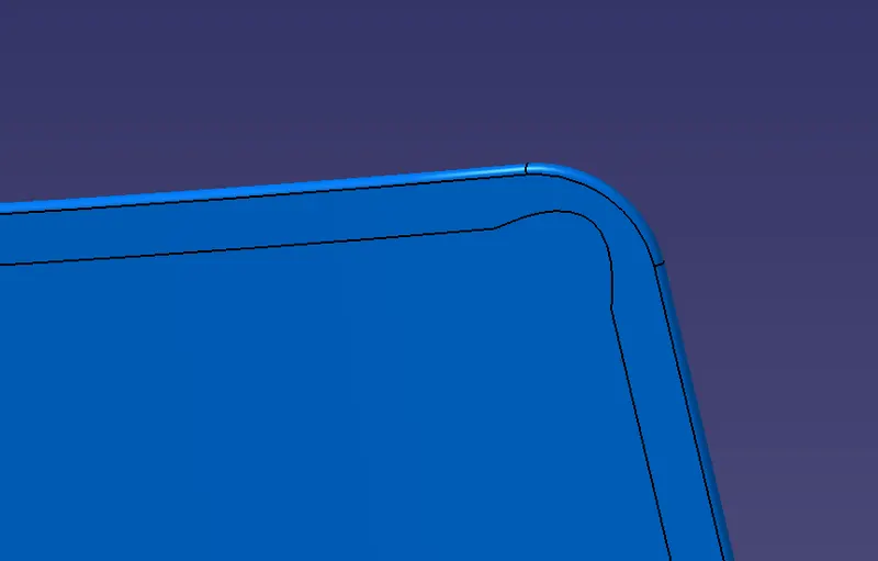
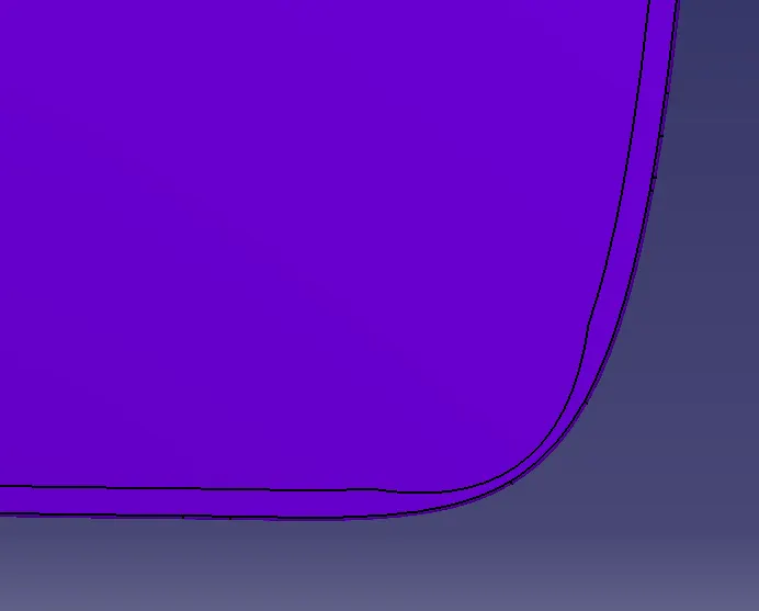
Finally, I have got the final output of the outer panel and symmetry it on the other side for joining.
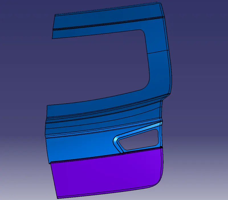
While symmetry the half portion, it was showing the topological error.
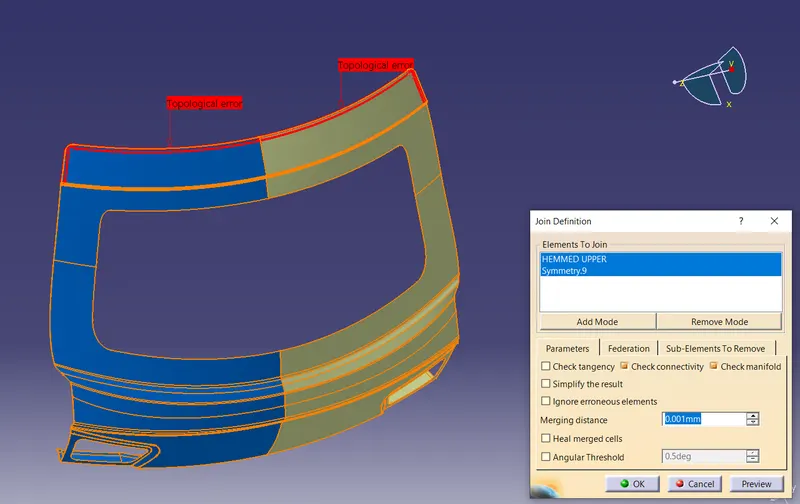
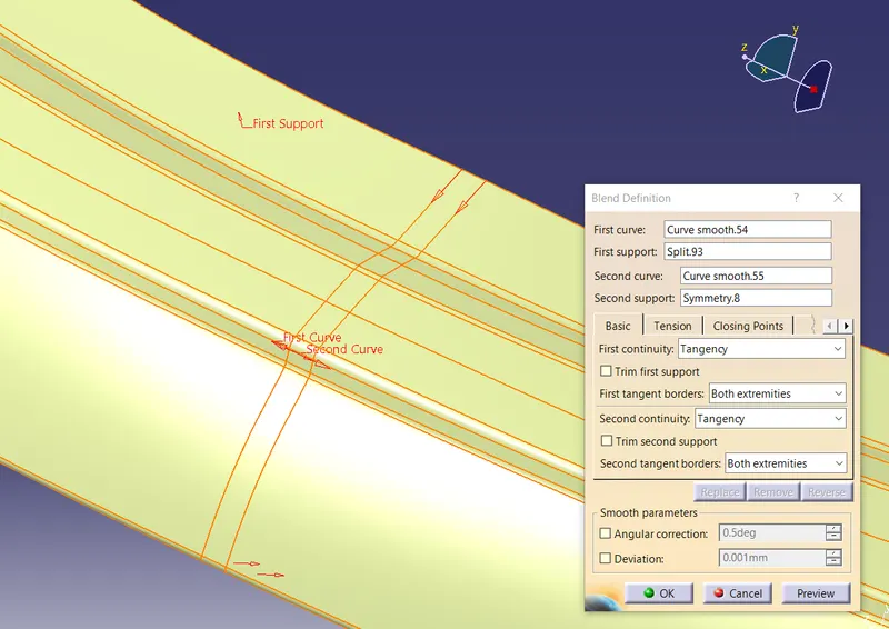
To fix it, first I have split the surface by giving a parallel curve by 10mm and symmetry it on the other side and then used Blend operation and joined surfaces.
Creating a Tooling axis:
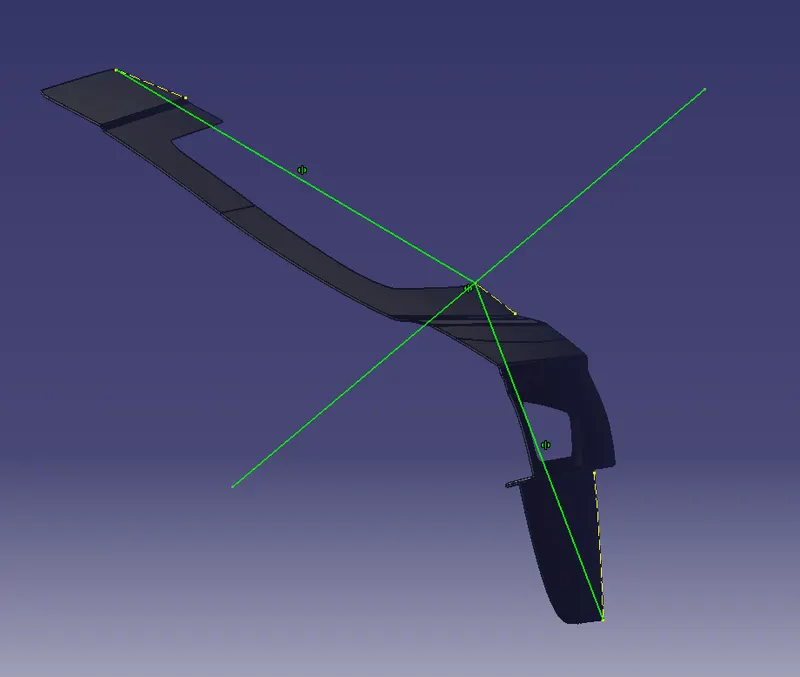
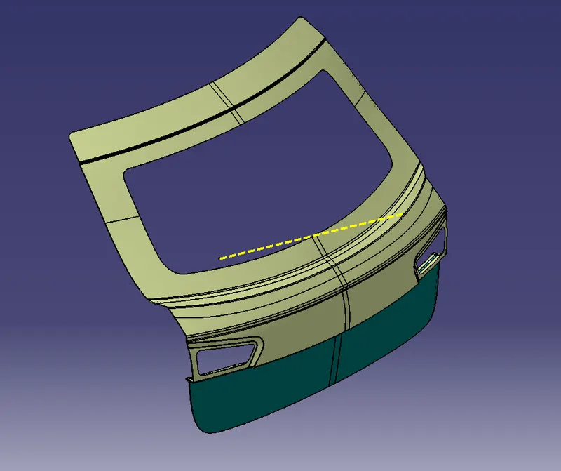
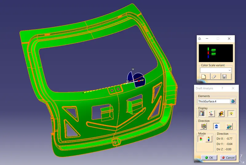
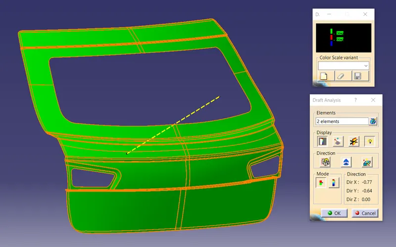
The tooling axis is created to get parts easily manufactured by giving an opening angle of more than 3 degrees in the Deep drawing process.
For creating tooling axis,
- First I have created a positioned sketch.
- Next draw the two lines along the surface: the first line from the end vertex to the center of the part and the second from the center to another end of the part.
- Then make a bisecting line between two lines and get the tooling axis.
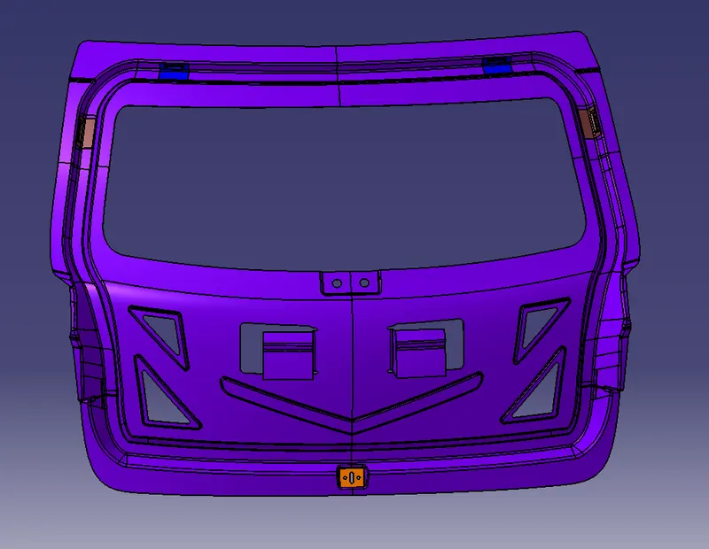
Creating an Inner panel:
- Sealing flange:
To create the sealing flange,
First I have extracted the surface by neglecting the fillets and offset it inner side up to 1.7mm to maintain the 0.2mm gap between the inner panel and outer panel including part thickness.
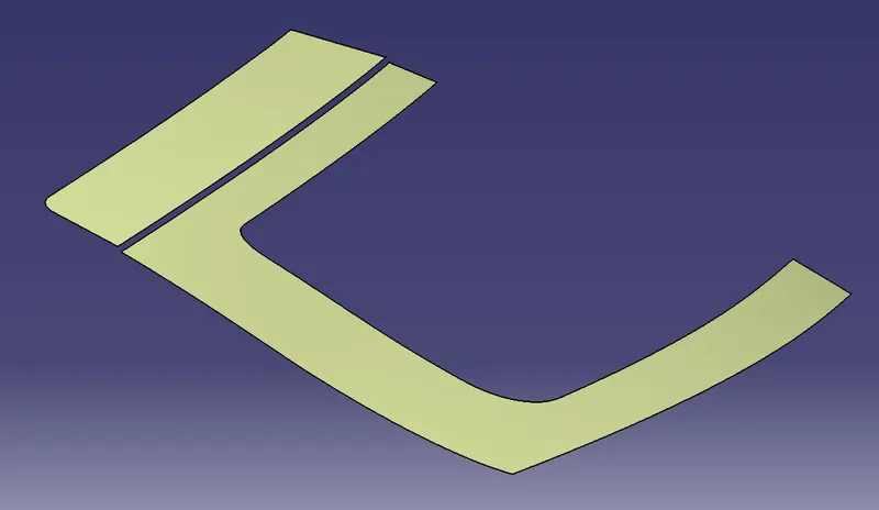
Next I gave a 25mm offset to this surface and then worked on it.
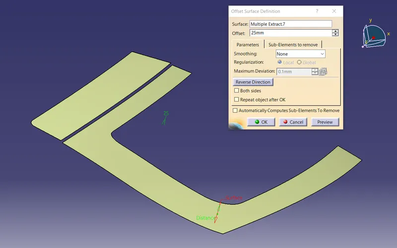
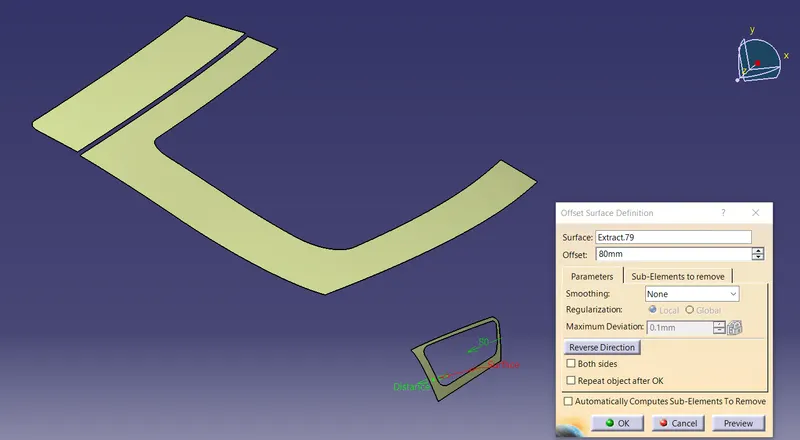
After that, the bottom flange is kept here at 30mm. The tail light area is untrimmed to get a smooth surface and offset to 80mm.
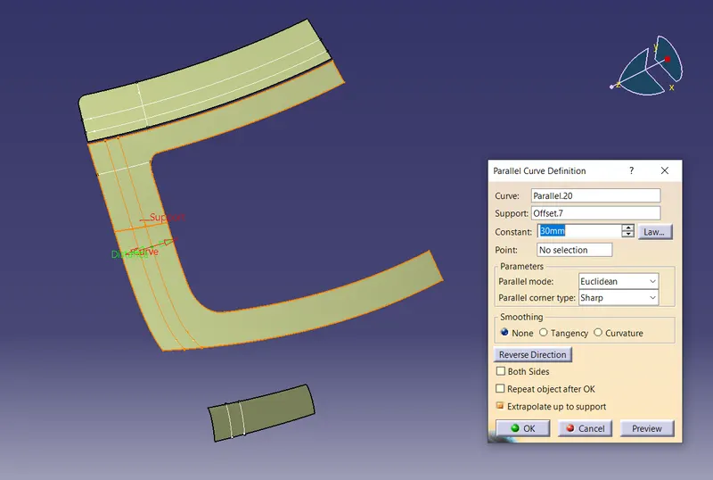
Then we give a parallel curve and split it with the surface.
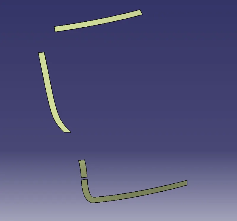
Join the flanges with each other using a Multi-section surface.
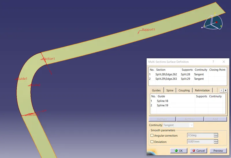
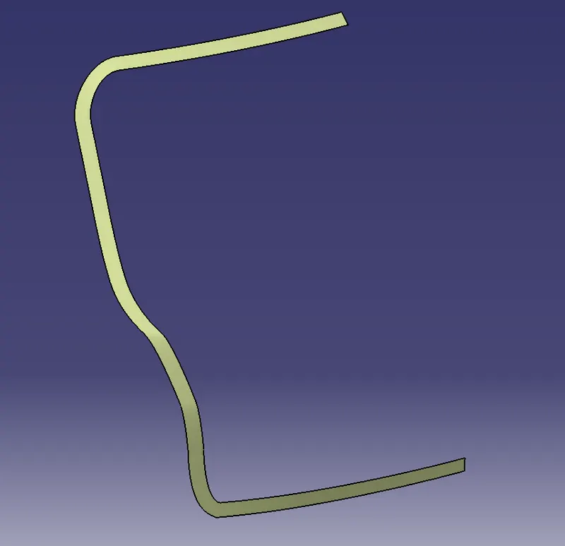
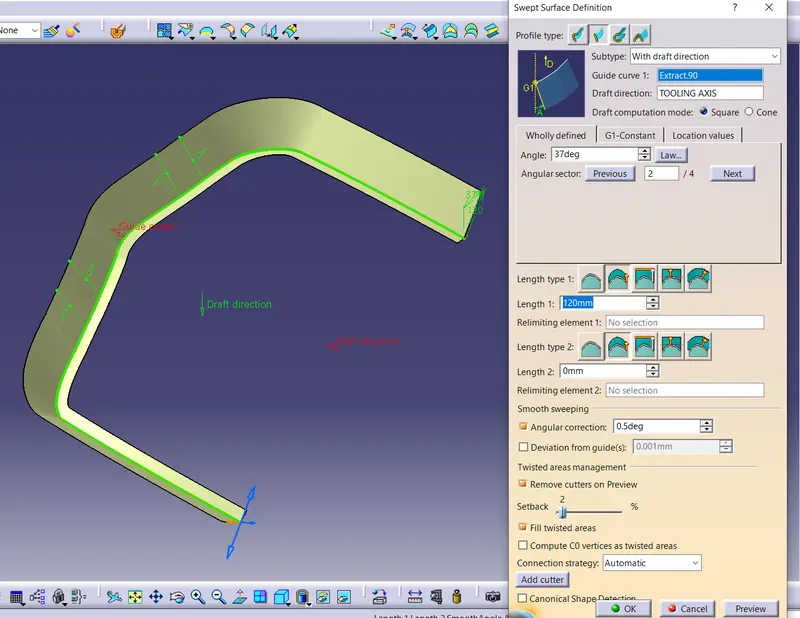
Sweep this surface using a tooling axis with a 37-degree draft angle.
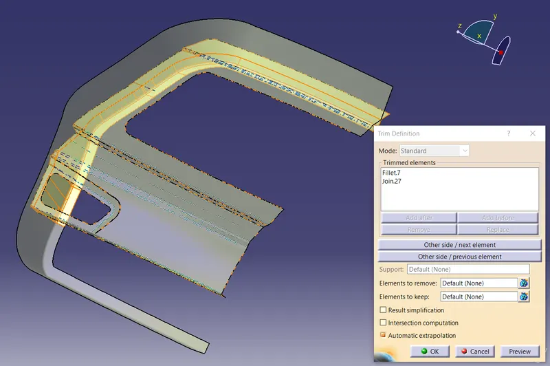
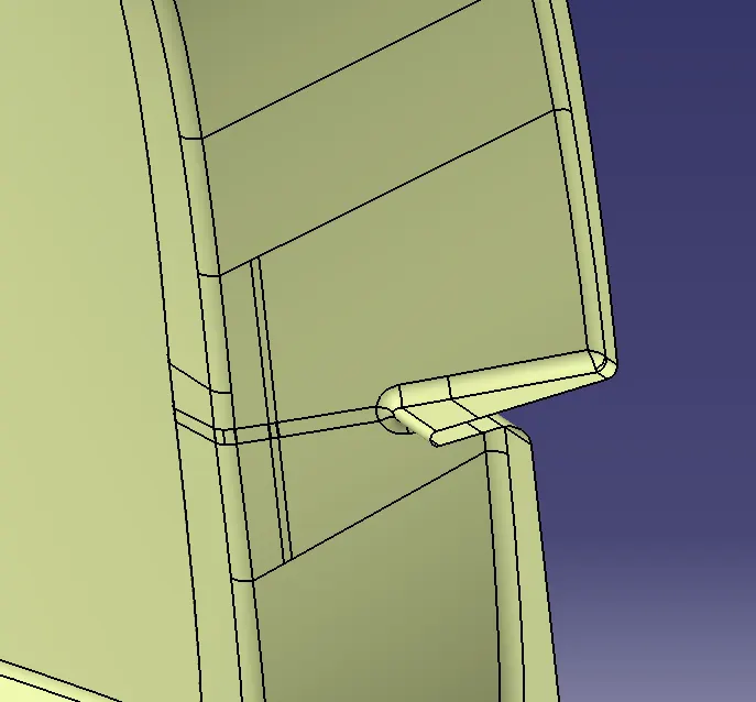
Trim it with the 1.7mm offset surface of the outer panel, providing the required fillets of a minimum of 5mm to remove sharp edges.
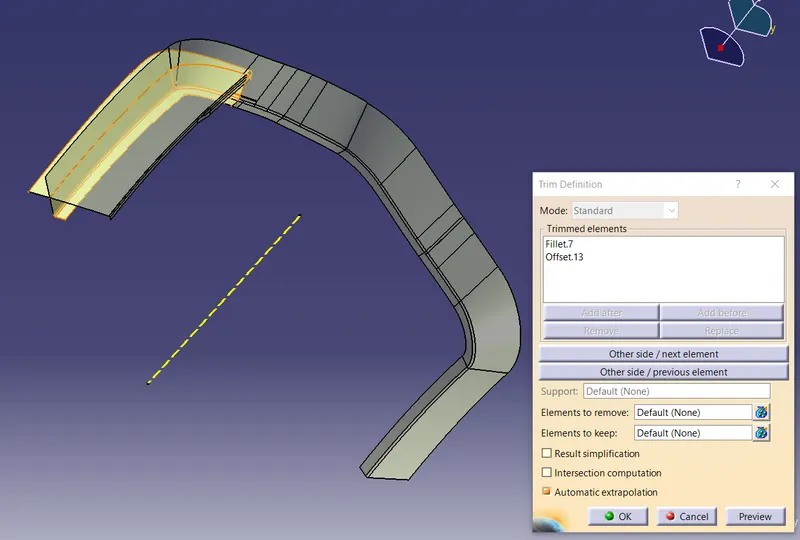
Join the lower and upper sections by using connect curve and sweep with two guide curves.
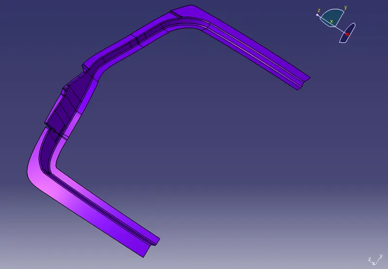
- Windshield support:
Similarly, Sweep the sealing flange in the inward direction of the 20-degree draft selecting tooling axis.
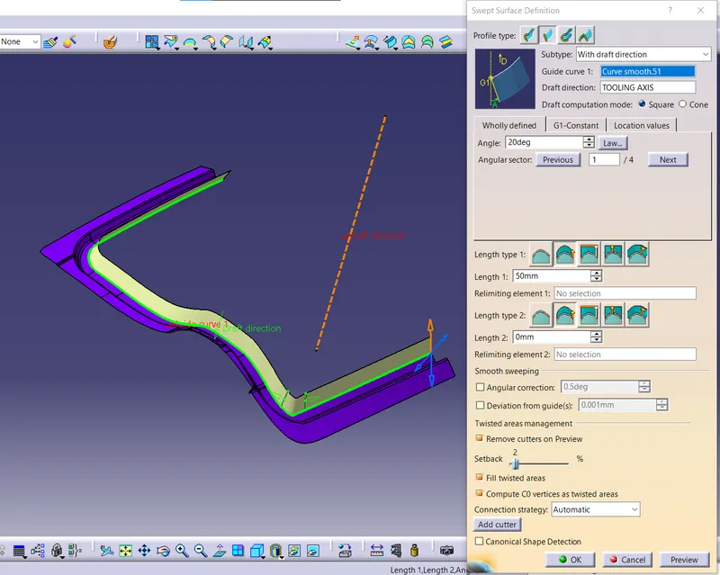
- Then extracted the windshield area and extrapolated it to intersect with the sealing flange.
- For the lower surface, use a spline with 0.6 tangencies on both sides and give multi-section surfaces.
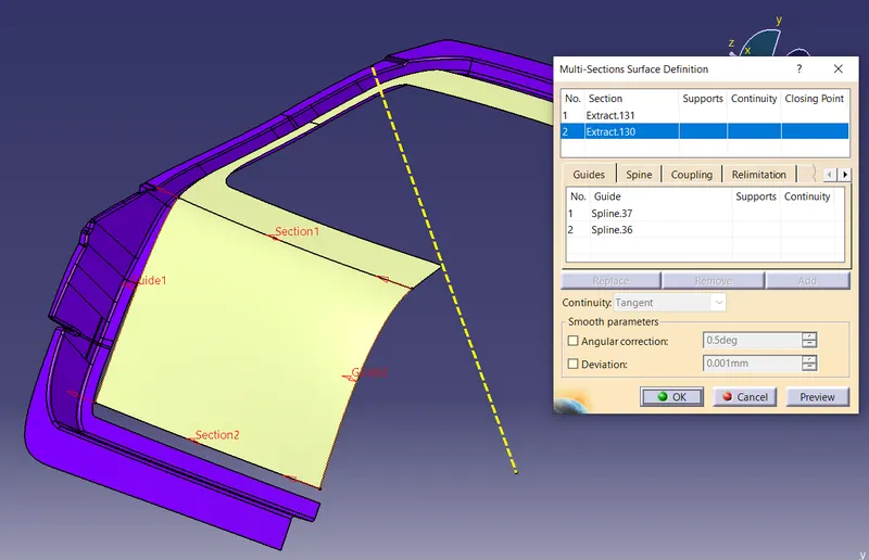
Joined the sealing flange and sweep surface, and multisection surface and windshield area separately.
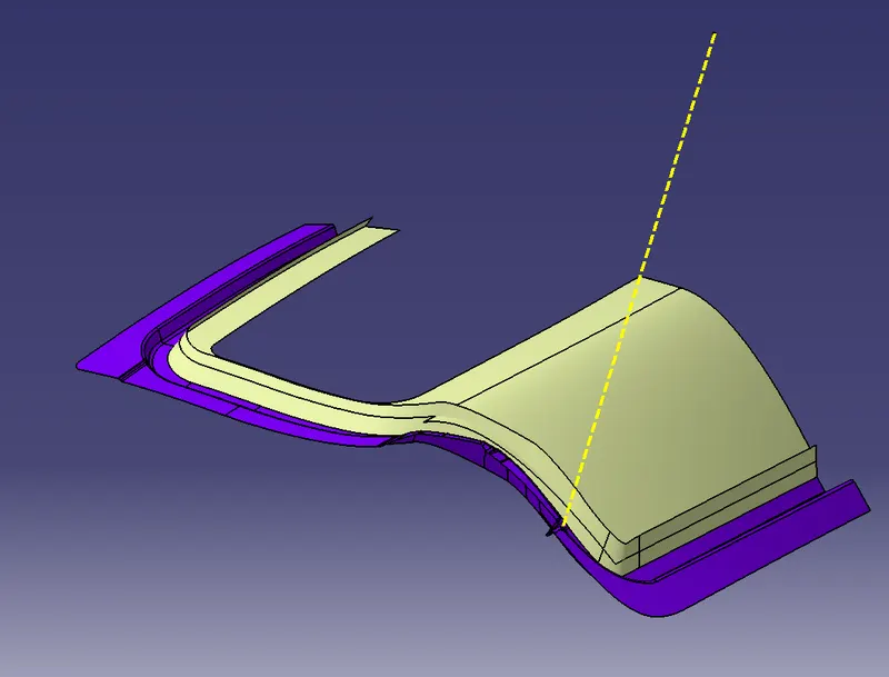
Extrapolate both the surface and provide a face fillet of 5mm and finally, we get the inner panel.
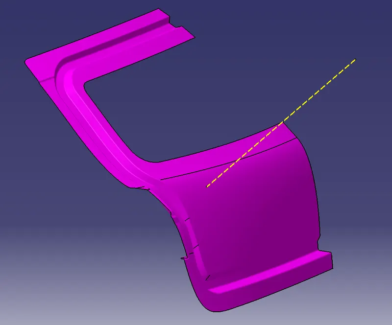
- Mastic region:
Since we are focusing to reduce the overall weight of the component we also need to provide strength to the component through mastics. It used to join the inner and outer panel and resists colliding during motion.
It also helps to reduce the NVH(Noise, Vibrations, and Harshness) of the back door as well as the vehicle.
First I created the sketch and projected it on the surface then split it with the surface.
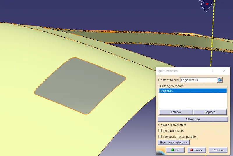
Here, I have maintained the 5mm gap between the inner and outer panel for the mastic region by offsetting the upper surface up to 5mm toward the inner side.
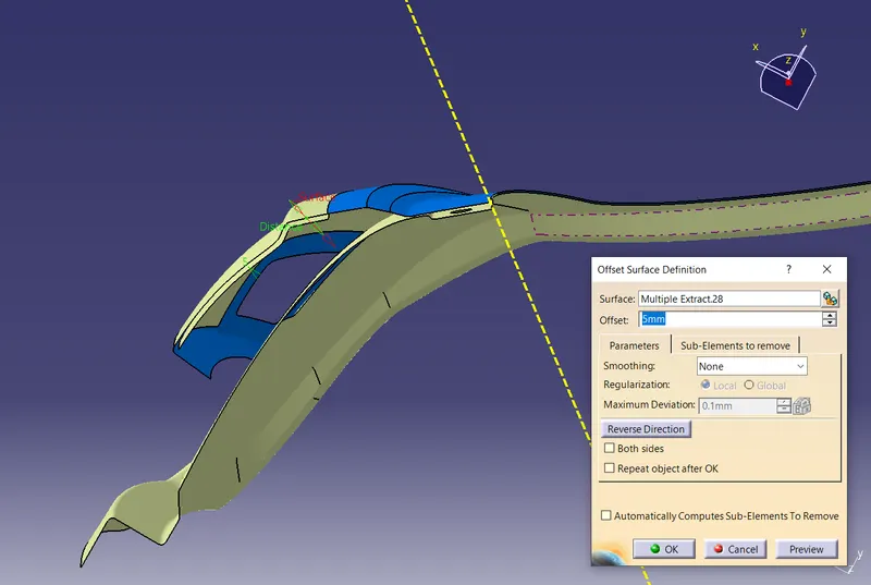
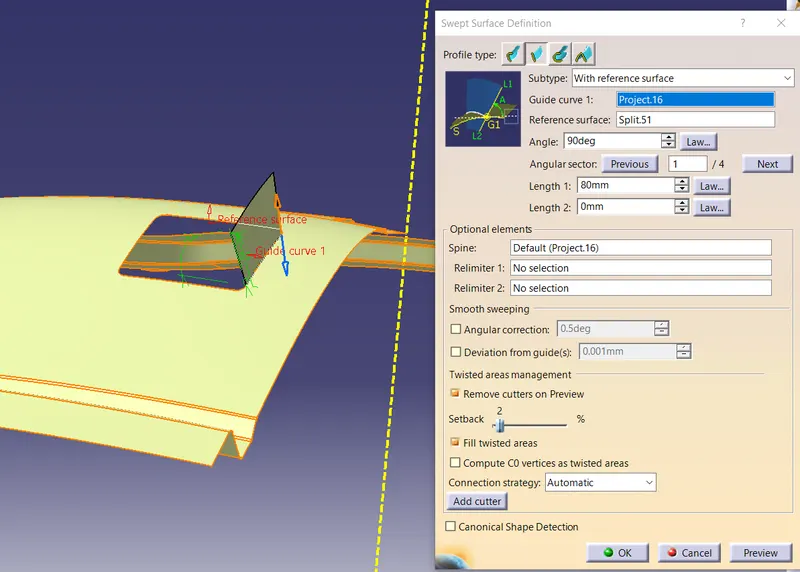
After that sweeping the surface to the perpendicular direction and trim it with the offset and cut off the unnecessary surface area,
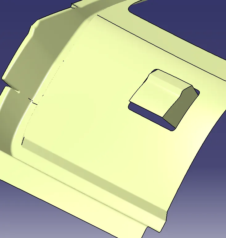
Finally, give the corner reliefs on the sharp corners by making splines and then splitting and providing the required fillets.
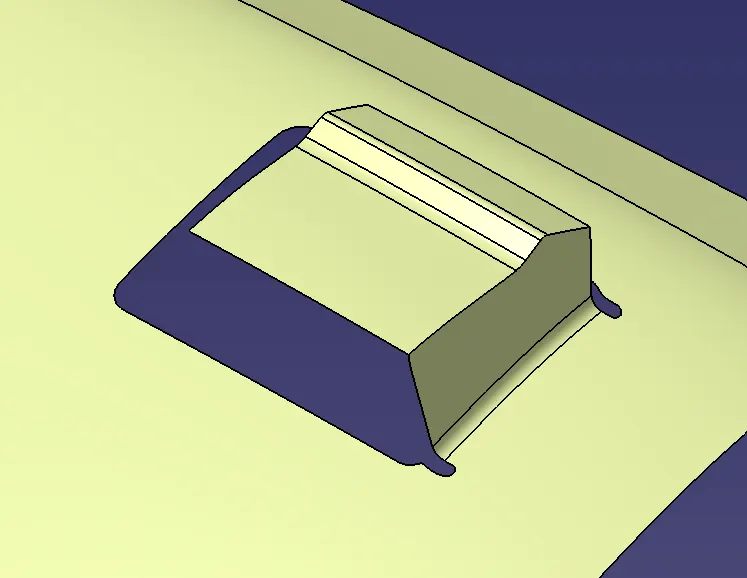
- Emboss:
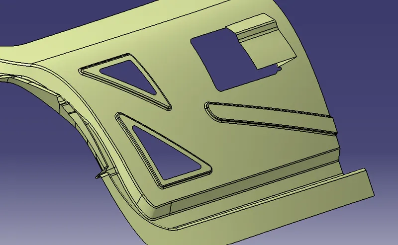
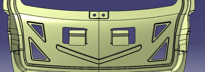
The purpose of the embosses area is to reduce the weight of components as well as provide strength and give the direction to the load during crash towards the sealing flange.
Also, the rear lights are going to be mounted after the assembly on BIW so I have given the emboss as a hole for the wiring.
During the simulation of BEND TEST, TORSION, AND ABUSE CASES the forces distribution towards the hinges and gas stay are smoother in V and Y shape so, I have given the emboss in V and Y shape.
- Hinge and Gas stay:
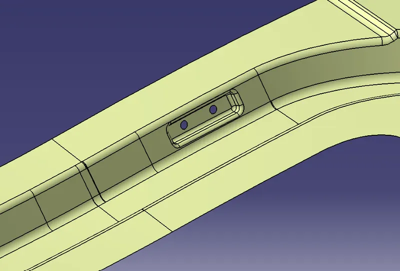
- Hinges are provided to give the opening and closing angle to the door after all the hatchback is hinged at the top.
- To create the hinge emboss, draw the sketch and project it on the surface then split it.
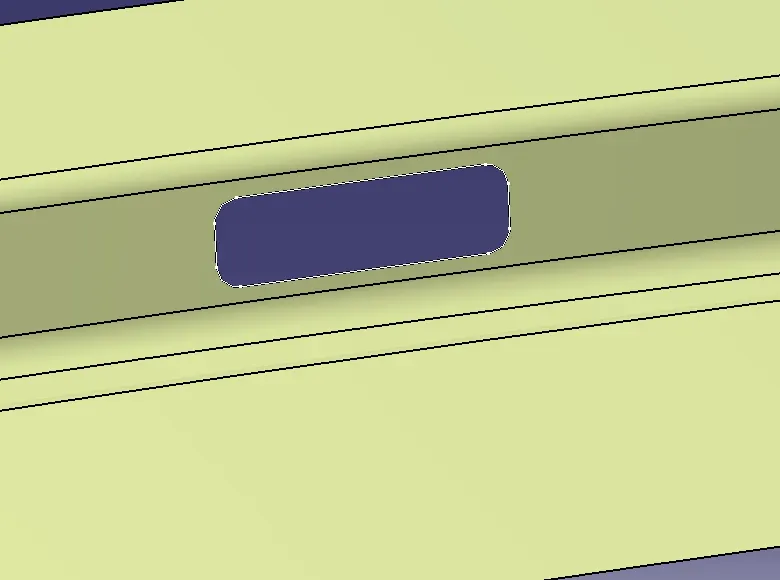
Sweep the cut out with a 7-degree draft angle, trim it with the 5mm offset and give 2-3mm fillets.
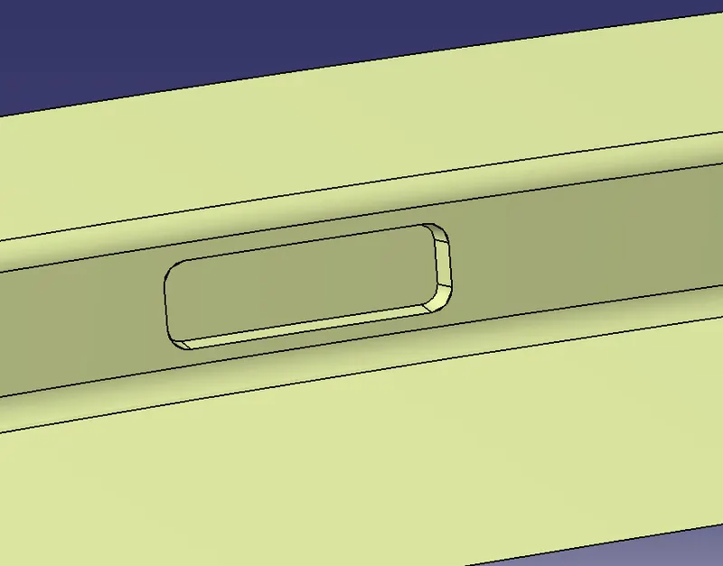
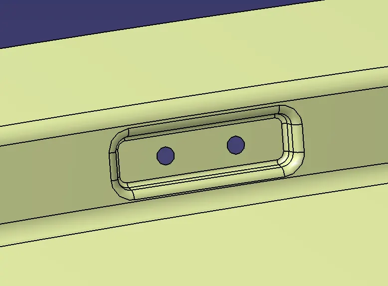
Gas stay helps to hold the door in the opening condition and also reduces the human effort to close and open the back door.
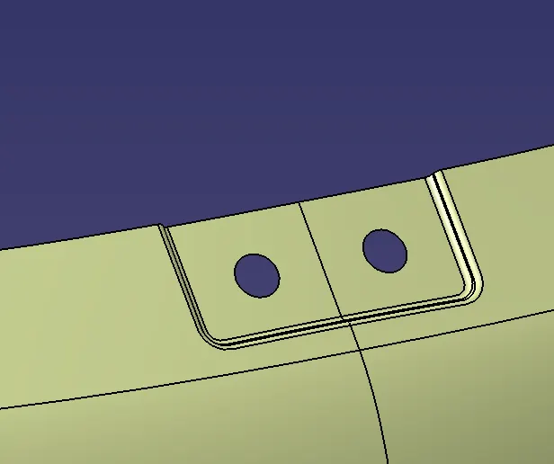
- Wiper:
Similarly as hinges and gas stays, also give the emboss to mount the wiper motor.
- Latch:
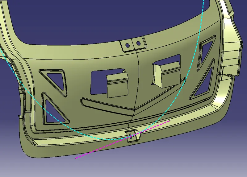
The latch is mounted on the center of the door and moves along its circular trajectory. For the latch, I have given embossment considering the trajectory movement.
- First I find the center of the hinges on the body through points and create the sketch and find the positioning of the latch by drawing a circle from the center point.
- Next created the tangent line of the circle and got the point and created a sketch on it for the latch.
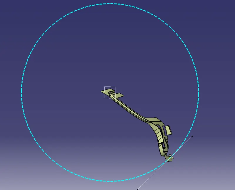
Then sweep the to the draft direction of a 10-degree draft angle and trim it with the offset providing fillets.
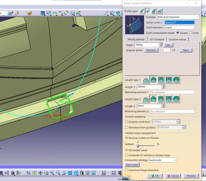
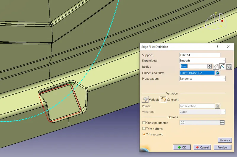
After that, I created the sketch for the cutout and projected on the surface, and split it.
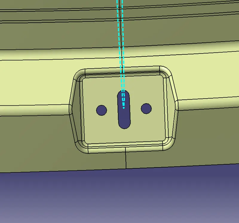
This will be the latch trajectory and movement direction for the latch.
- Reinforcements:
Reinforcements are sheets between two parts to make the assembly and region of fixation stronger and to increase the strength of the part.
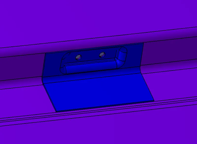
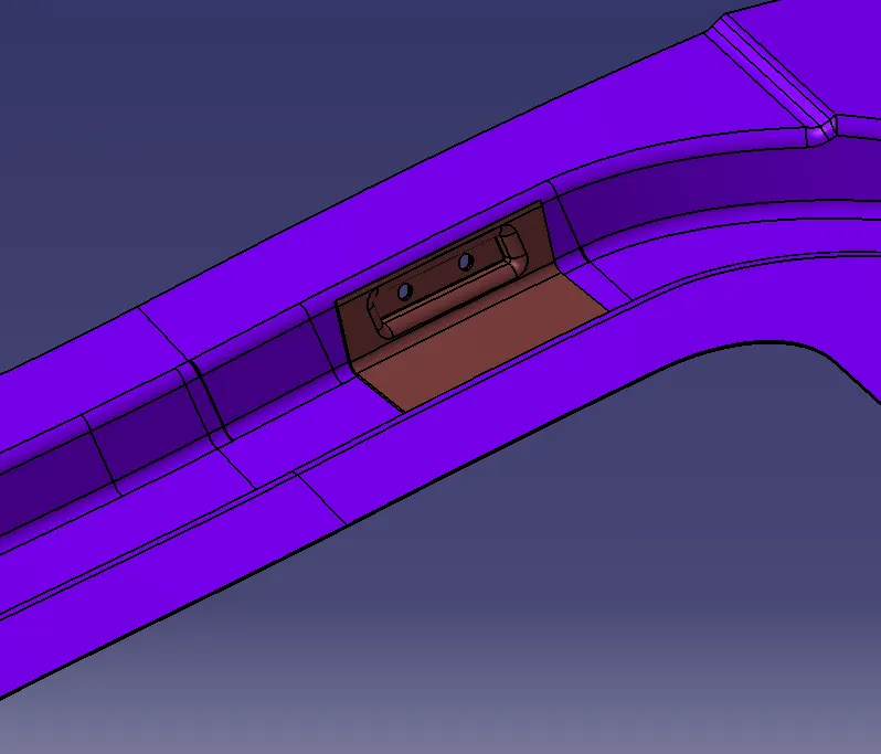
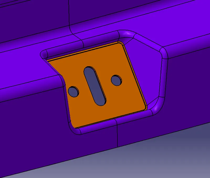
To create the reinforcements just extracted the surfaces of hinges, gas stays, and latch and split the extra surfaces, and offset it for 0.75mm which is the thickness of the inner panel.
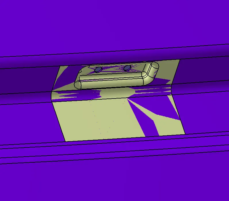
The thickness of reinforcements should be a minimum of 1mm.
- Hinge reinforcement:
- Gas stay reinforcement:
- Latch reinforcement:
Creating a solid:
The thickness of the inner and outer panels is 0.75mm and reinforcement is 1mm.
Results:
- Inner panel:
- Upper outer panel:
- Lower outer panel:
- Section view of the hemming region:
- Corner reliefs:
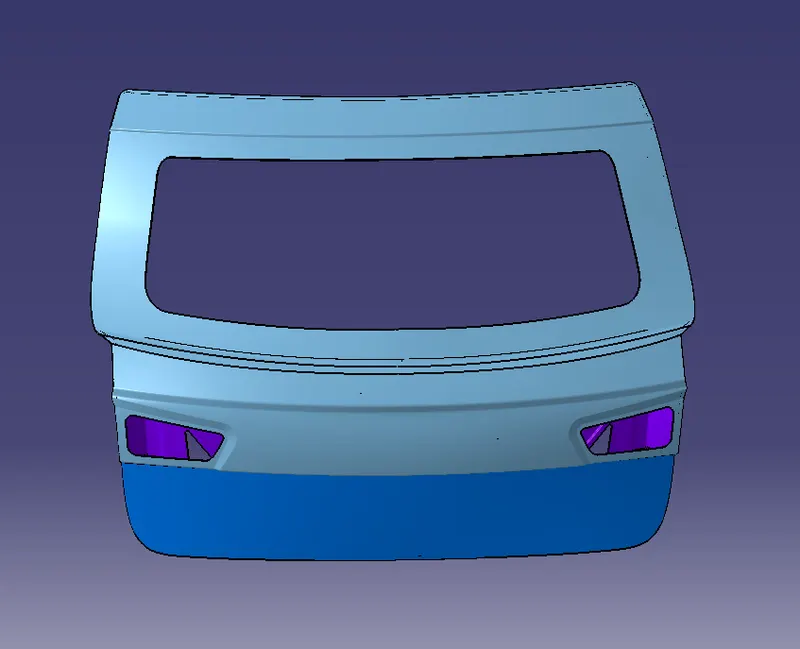
- Final Assembly:
- Draft analysis:
Conclusion:
The back door (Hatchback) is created considering all parameters and safety standards with the proper draft angle to make the part manufacturable.