Cyclone Separator Challenge
AIM: To perform simulation of a cyclone separator by changing the size and velocity of the particles.
INTRODUCTION: The cyclone separator is used to separate waste material or for product recovery. This is very simple in geometry, economic in power, and flexibility. I am using a standard model for this simulation and the material used are anthracites of different diameters. And I have used three different inlet velocities for each size.
THEORY: In this process, I have used the k-epsilon turbulence model, RNG, with swirling effects enabled.
EMPIRICAL MODELS OF CYCLONE SEPARATOR EFFICIENCY:
- IOZIA AND LEITH MODEL: An empirical model for predicting pressure drop across a cyclone separator. To develop an optimization curve that predicts the minimum pressure drop and the dimension ratios of the optimized cyclone for a given aerodynamic cut diameter. the effect of variation in cyclone height, diameter, and flow on the optimization is determined. The optimization results are used to develop a design procedure for optimized cyclones.
- LI AND WANG MODEL: The Li and Wang model include particle bounce or re-entrainment and turbulent diffusion at the cyclone wall. A two dimensional analytical expression of particle distribution in the cyclone is obtained. Li and Wang model was developed based on the following assumptions.
The radial particle velocity and the radial concentration profile are not constant for uncollected particles within the cyclone.
Boundary conditions with the consideration of turbulent diffusion coefficient and particle bounce re-entrainment on the cyclone wall.
The tangential velocity is related to the radius of cyclone by `uR^n = constant`
- KOCH AND LICHT MODEL: Koch and Licht collection theory recognized the inherently turbulent nature of cyclones and the distribution of gas residence times within the cyclone. Koch and Licht described particle motion in the entry and collections regions with the additional following assumptions:
The tangential velocity of a particle is equal to the tangential velocity of the gas flow that is there is no slip in the tangential direction between the particle and the gas.
The tangential velocity is related to the radius of the cyclone by: `uR^n = constant`
- LAPPLE MODEL: It is the earliest model amongst the proposed and still considered the benchmark for the design of cyclone separator in many industries. This is comparatively a simple model based on force balance without considering the flow resistance. It assumes that the particles are evenly distributed across the inlet while entering the cyclone. It was based on the terminal velocity of particles in the cyclone.
- Lapple assumed that a particle entering the cyclone is evenly distributed across the inlet opening. The particle that travels from inlet half-width to the wall in the cyclone is collected with 50% efficiency.
MODEL DESCRIPTION:
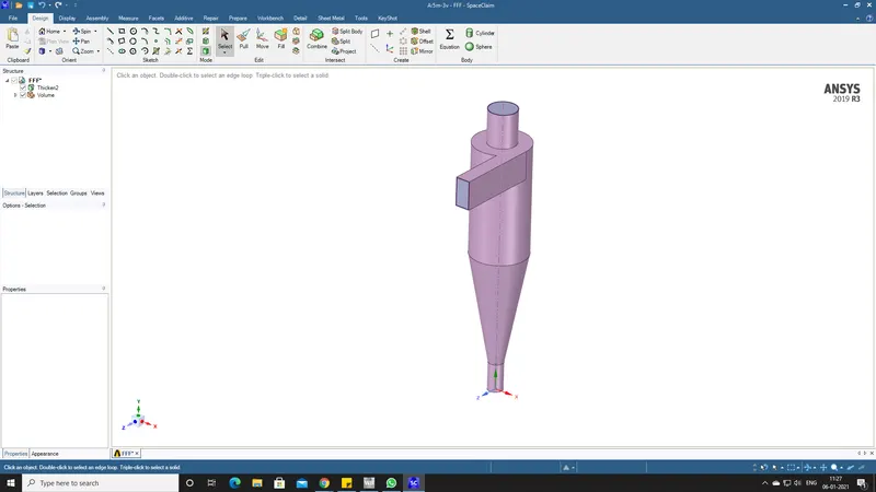
Geometry editing in Space Claim.
- In, this analysis we editing geometry is not as complicated as previous challenges.
- Here, we just extract the volume from the model and make the model suppressed for physics.
MESHING:
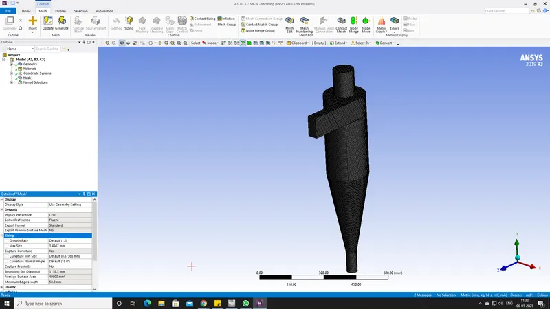
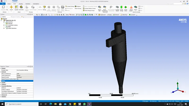
- The mesh size is 3.5mm.
- The mesh type here is cut cell. We can find that option in the Assembly Meshing section on the left bottom side.
- Name the inlet and outlets.
FLUENT SOLVER:
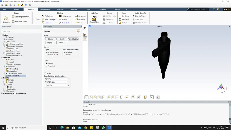
- Initially, enable the gravity model and give the appropriate value (9.81).
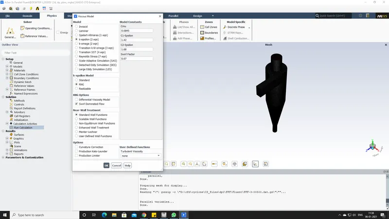
- Next, set the turbulence model as shown in the picture.
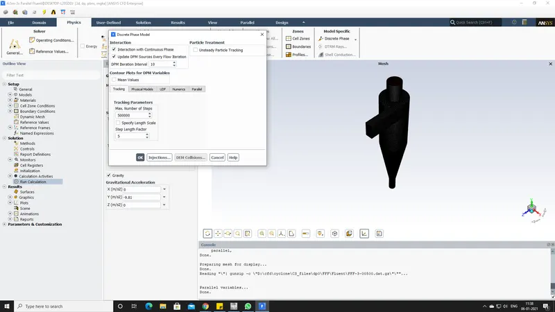
- Lastly, enable the DPM(Discrete Phase Model). Leave everything to default values and set the injection materials.
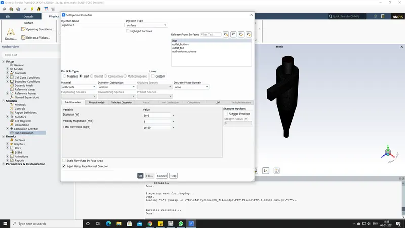
- The injection materials are anthracites of 5 micrometers, velocity is 3 m/s, and set the release surface to the inlet.
- General Information
- Turbulence settings
- DPM setup
- Injection material setup.
BOUNDARY CONDITIONS:
- The boundary conditions for this simulation are as follows.
- As I am using DPM the inlet will be velocity inlet and DPM is set to Reflect.
- Outlet bottom will be pressure outlet and DPM is set to trap.
- The outlet top will also be a pressure outlet and DPM is set to escape.
SOLVER:
- After completing the above settings, use standard initialization through the inlet and run the simulation for about 500-600 iterations.
- However, the solution seems to be converged at 200 iterations.
- In my case, a total of 435 particles have traces in all simulations.
- Lastly, after completing the calculations export the particle history data for further analysis.
RESULTS/POST-PROCESSING:
- In CFD post-processing, import the particle history data and you see a new option popping up naming FLUENT PT for Anthracites.
- The particle history data will show the anthracite paths in which direction they have traveled. We can also increase the number of paths through the inlet.
- Increase the cyclone separator wall transparency to witness the paths clearly.
- Next, color the particle data using anthracite particle time and it will show the time taken to travel from the inlet to the outlet.
PARTICLE SIZE: 5M
- Velocity: 1m/s.
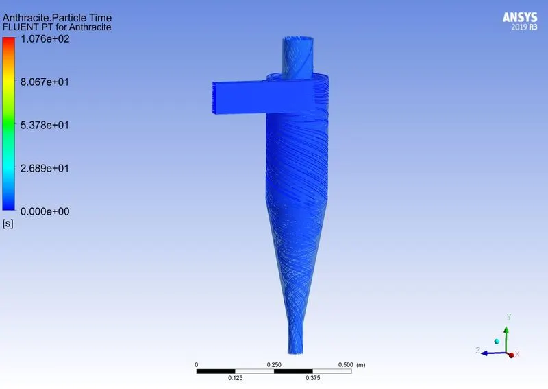
- Velocity: 3m/s.
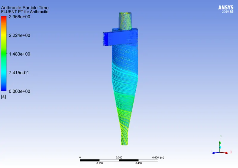
- Velocity: 5m/s.
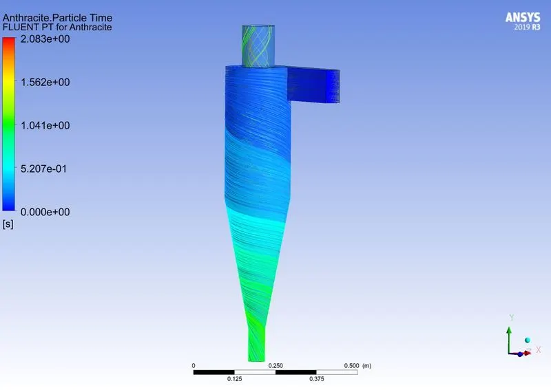
PARTICLE SIZE: 3m
- Velocity: 1m/s.
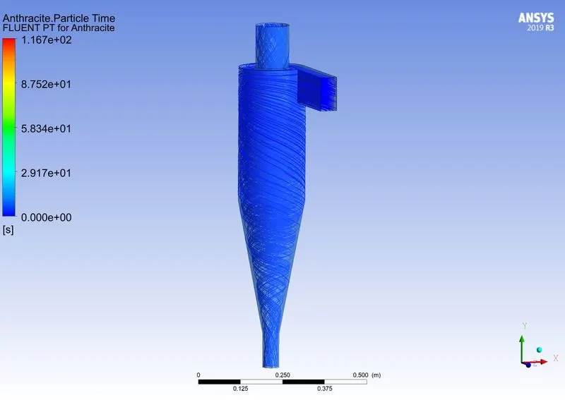
- Velocity: 3m/s.
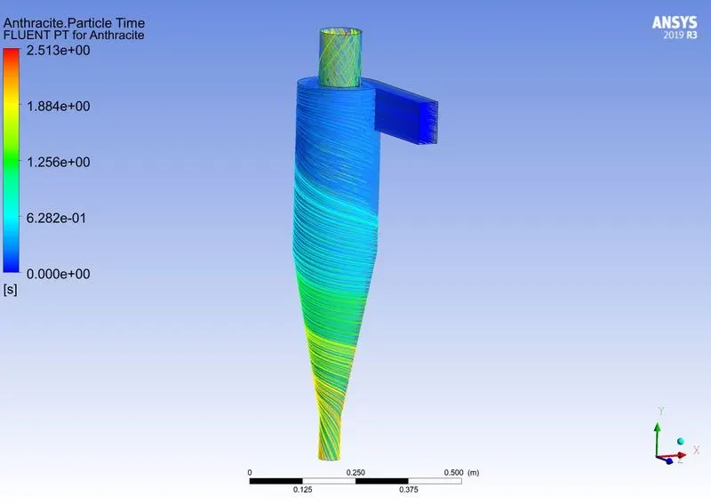
- Velocity: 5m/s.
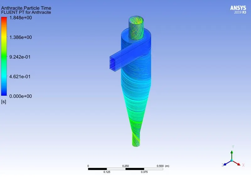
PARTICLE SIZE: 1m
- Velocity: 1m/s.
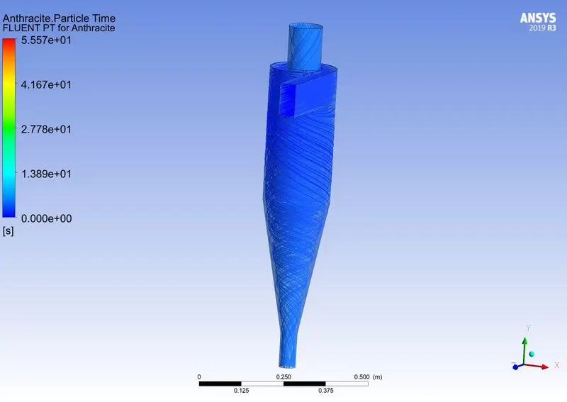
- Velocity: 3m/s.
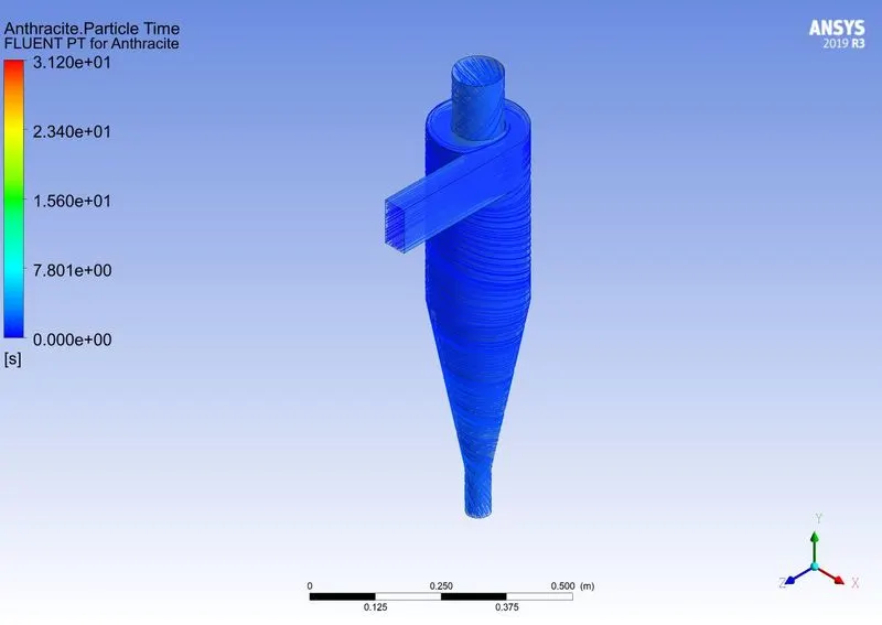
- Velocity: 5m/s.
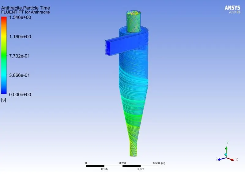
CALCULATING SEPARATOR EFFICIENCY:
- There are a few formulas to find the efficiency of the cyclone separator. Among them, the most popular formula is Iozia and Leith Model.
- Which is developed based on force balance. The model assumes that a particle carried by the vortex endures the influence of two forces: a centrifugal force, Z and a flow resistance, W. The collection efficiency `eta` of particle diameter `d_(p i)` can be calculated from
`eta_i=1/(1+(d_(pc)/d_(p i))^beta)`
`beta` is expressed based on the statistical analysis of experimental data of a cyclone with D = 0.25m
- According to some research papers
`beta==0.62-0.87ln((d_(pc))/(100))+5.21ln((ab)/D^2)+1.05[ln((ab)/(D^2))]^2`
| Size | velocity (m/s) | Total Particles Reflected | Escaped | Traped | Incomplete | Efficiency |
| 5 micrometer | 1 | 435 | 219 | 114 | 102 | 20% |
| 5 micrometer | 3 | 435 | 129 | 306 | 0 | 70% |
| 5 micrometer | 5 | 435 | 47 | 388 | 0 | 89% |
| 3 micrometer | 1 | 435 | 227 | 112 | 96 | 25% |
| 3 micrometer | 3 | 435 | 188 | 247 | 0 | 56% |
| 3 micrometer | 5 | 435 | 168 | 272 | 0 | 62% |
| 1 micrometer | 1 | 435 | 235 | 108 | 92 | 24% |
| 1 micrometer | 3 | 435 | 214 | 218 | 3 | 50% |
| 1 micrometer | 5 | 435 | 216 | 219 | 0 | 50% |
CONCLUSION:
- Cyclone separators are very helpful in chemical industries to remove the dust particles from the gas.
- These types of machinery don't require much energy and space. They are economic in usage.
- After calculating the efficiency and checking particle data. I conclude that the particles with greater mass and higher velocity gained higher efficiency.
- In my case study, the particles with 5 & 3 micrometers with velocities 3 and 5 meters per second each have completed the simulation in less time.
- However, efficiency also depends on the model and dimensions of the separator.