Cyclone Separator Challenge
1. The aim, Introduction, Theory:
The main objective of this challenge is to investigate the performance characteristics of Cyclone seprator and to detrmine its sepration efficiency by varying the dispersed particles size from 1 micro-meter to 5 micro-meter and inlet velocity from 1m/s to 5m/s.
Cyclone seprator is a device generally used to seprate out the perticulate matter from the gases in order to control the air pollution. Cyclone seprators are availble in various sizes and design mainly used in coal thermalpower plants. When large numbers of cyclone seprator operates parallel to each other they are called as multi cyclone seprator.
The cyclone seprator works on centrifugal action which creates a vortex region inside the container and this vortex action of gases seprates out the lighter particles which tends to flow out of upper outlet section while the large heavy particles tend to hit the walls of container and settles down and get collected at bottom outlet.
Cyclone seprators are more effective when the size of perticulate is between 2.5 micro-meter to 200 micrometer.
Usually the sepration efficiency of cyclone seprator varies from 55 to 99 %.
Empirical Models for Cyclone sepration Efficiency:
i) IOZIA AND LEITH MODEL: This model assumes that particles carried by the vortex will experience two major forces one is centrifugal force and second is flow resistance. The sepration efficiency obtained by this model is expresses as
ηi =1/1+(dpc / dpi)^β
Where
ηi= sepration efficiency.
dpi= particle diameter.
ii) LI AND WANG MODEL: The Li and Wang (1989) model includes particle bounce or
re-entrainment and turbulent diffusion at the cyclone wall.
- Li and Wang model was developed
based on the following assumptions:
The radial particle velocity and the radial concentration
profile are not constant, for uncollected particles within the
cyclones.
Boundary conditions with the consideration of turbulent
diffusion coefficient and particle bounce re-entrainment on
the cyclone wall. - The tangential velocity is related to the radius of cyclone.
iii) KOCH AND LICHT MODEL: Koch and Licht (1977) collection theory recognized the inherently turbulent nature of cyclones and the distribution of gas residence times within the cyclone.
iv) LAPPLE MODEL:Lapple (1951) model was developed based on force balance without considering the flow resistance. Lapple assumed that a particle entering the cyclone is evenly distributed across the
inlet opening. The particle that travels from inlet half width to the wall in the cyclone is collected with 50% efficiency.
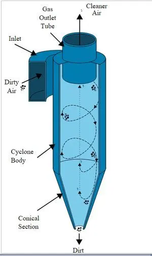
Figure 1. Cyclone Seprator.
2. Solving & Modelling approach:
A 3-D model is constructed as per the size of cylone seprator by using CAD software or geometry is created by using space claim.
The constructed 3-D model consist of both the outer solid surface and inner fluid volume but our domain of intrest is fluid volume which can be extracted out by using volume extraction command which is availble in space claim>prpepar> Volume extraction> egde tool> Extract>ok
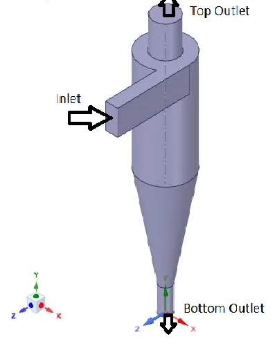
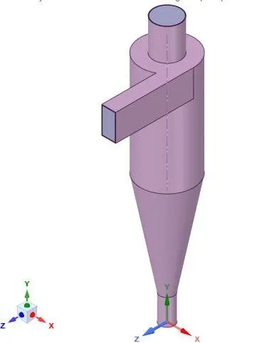
Fifure 2. (a) Extracted fluid Volume (b) Solid and fluid domain
3. Pre-processing and solver setting:
(a)
(b)
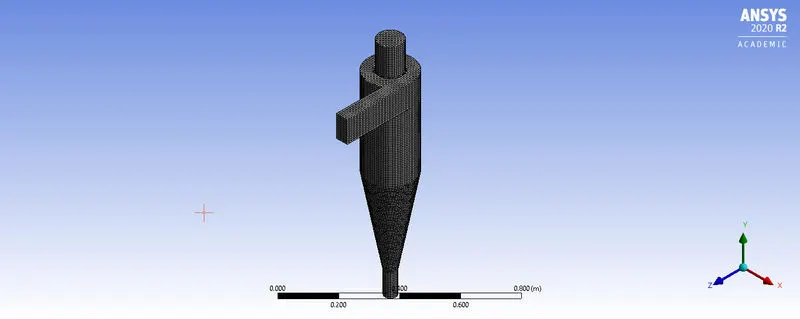
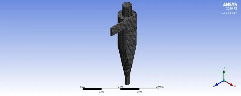
Figure 3. (a) Cut cell Mesh (b) Sectional view of mesh
Meshing: In order to get high accuracy for such swirling flow problems and to catch the physics of the fluid flow it is better to use cut cell type of hexahedral mesh.
In order to generate cut cell type of mesh go to mesh> Assembly meshing> method> Cut cell method> capture curvature on> generate Mesh.
If assembly meshing option is not available in the mesh window then go to workbench window click on tools>Appearance>options> put on the unsupported features.
The assembly meshing option will get activated in mesh window.
After generating mesh then go to setup
Number of Nodes=66728
Number of Elements=64338
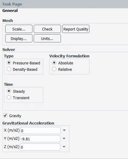
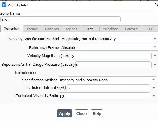
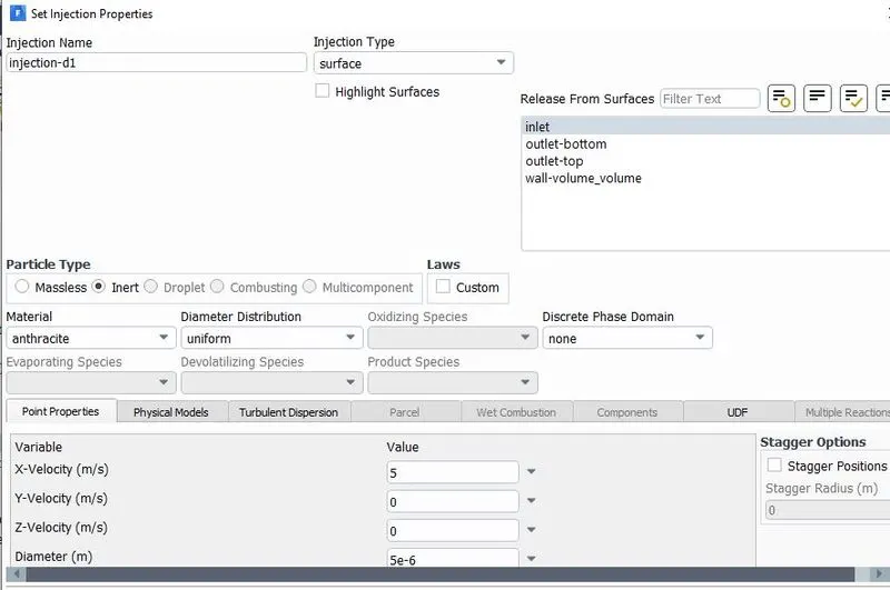
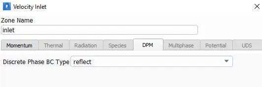
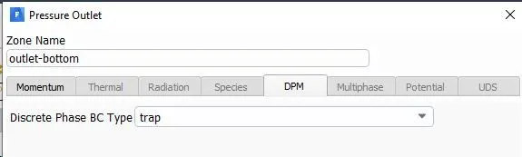
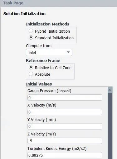
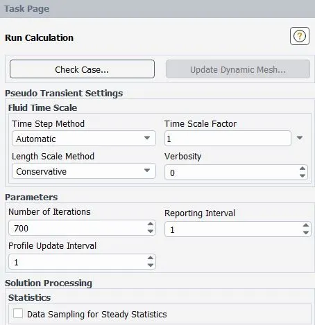
Setup:
4. Results:
| Sl No | Case | Inlet Velocity (m/s) | Particulate diameter(Micro-meter) |
| 1 | Case-1 | V=3m/s |
d1=1 d2=2 d3=3 d4=4 d5=5 |
| 2 | Case-2 |
V1=1 m/s V2= 2 m/s V3= 3 m/s V4= 4 m/s V5= 5 m/s |
d=5 |
Case-1: (Inlet velocity is kept 3m/s while particle diameter varies from d1 to d5)
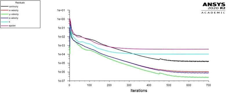
In case-1 the inlet flow velocity of fluid in the cyclone seprator is kept constant while the diameter of the suspended perticulate particle diameter changes from 1 to 5 micro-meter.
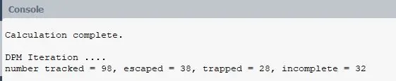
Seprator Efficiency= Number of particles trapped/ Number of particles tracked
= 28/98 *100= 28.57 %

Figure 4. Residual plots and Anthracite particle time (particle d1)

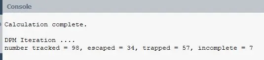
Seprator Efficiency= Number of particles trapped/ Number of particles tracked
= 57/98 *100= 58.16 %
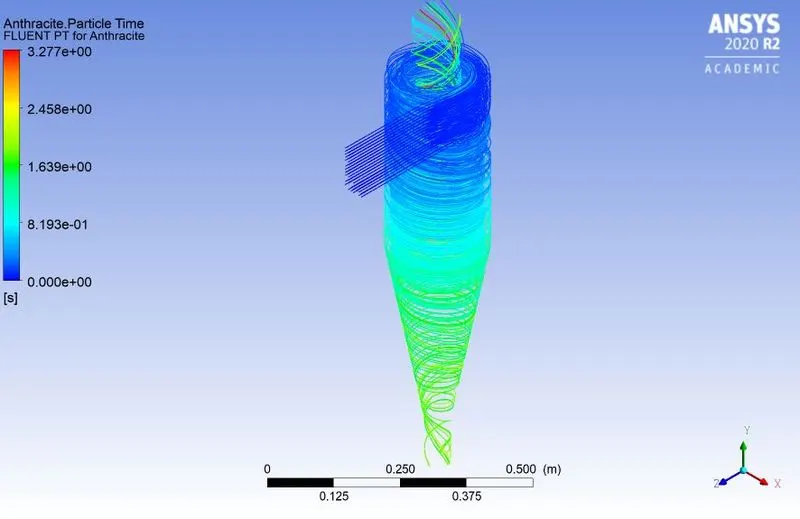
Figure 5. Residual plots and Anthracite particle time (d2 particle)
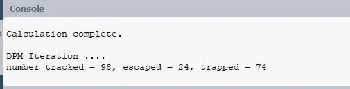
Seprator Efficiency= Number of particles trapped/ Number of particles tracked
= 74/98 *100= 78.72%
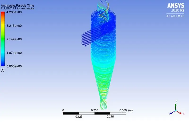
Figure 6. Residual plots and Anthracite particle time (Particle d3)
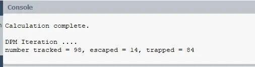
Seprator Efficiency= Number of particles trapped/ Number of particles tracked
= 84/98 *100= 85.71%
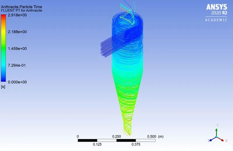
Figure 7. Residual Plots and Anthracite particle time (Particle d4)
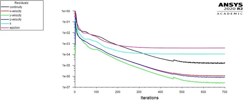
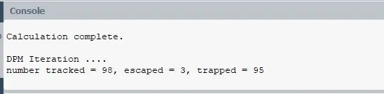
Seprator Efficiency= Number of particles trapped/ Number of particles tracked
= 95/98 *100= 97%
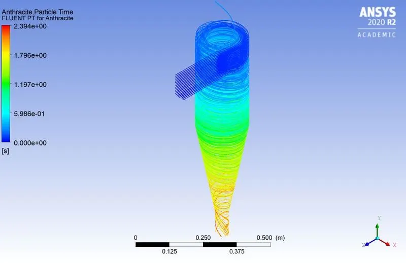
Figure 8. Residual plots and Anthracite particle time (Particle d5)
Case-2: Particle diameter is kept constant at d5=5 Micrometer, while the velocity at inlet is varied from 1m/s to 5m/s.
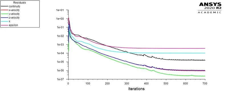
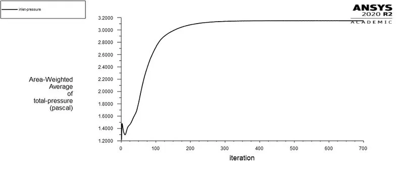
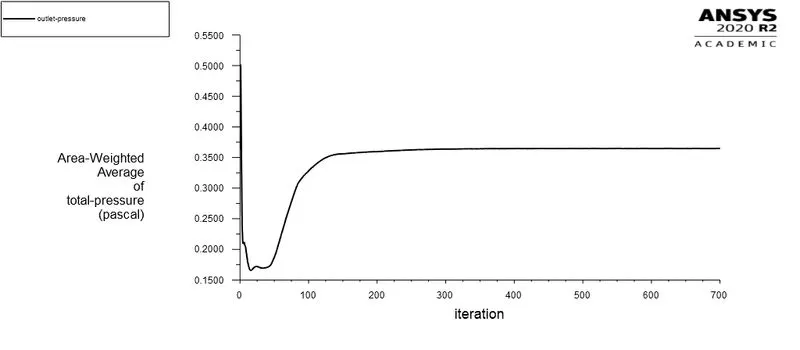
Total Pressure drop= Total inlet pressure - Total outlet pressure
= 3.1-0.35
= 2.75 Pascals.
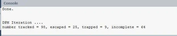
Seprator Efficiency= Number of particles trapped/ Number of particles tracked
= 9/98*100= 9.1%
Figure9. Residual plots, Inlet and outlet total pressure drop (V1=1m/s)
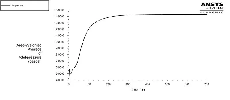
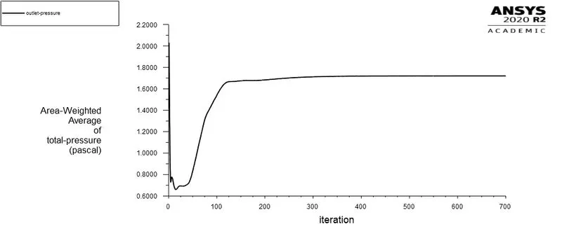
Total Pressure drop= Total inlet pressure - Total outlet pressure
= 14-1.7
= 12.30 Pascals.
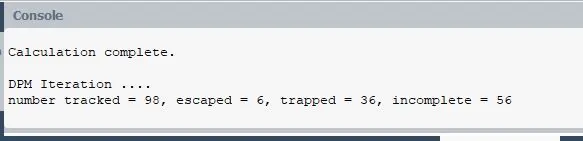
Seprator Efficiency= Number of particles trapped/ Number of particles tracked
= 36/98*100=37%
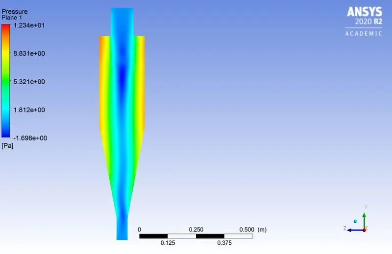
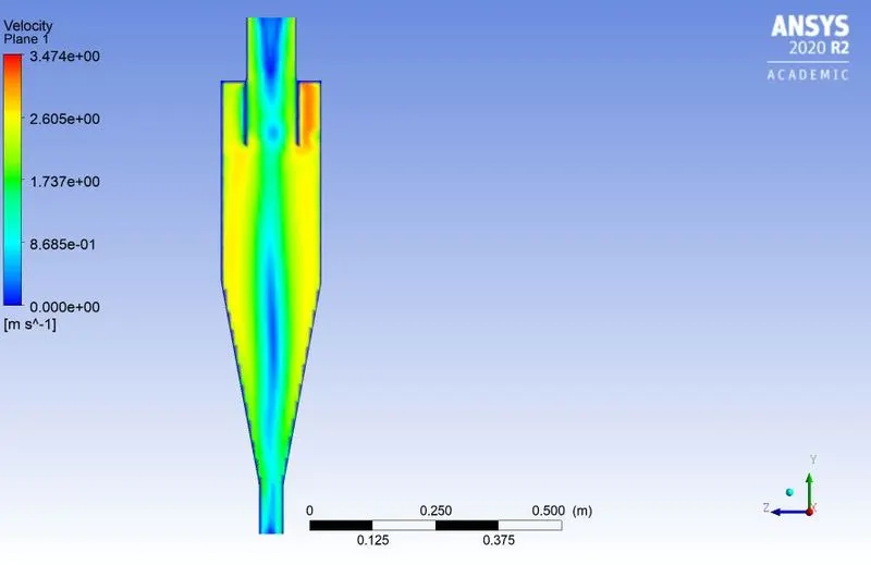
Figure 10. Residaul plots, inlet outlet total pressure, pressure and velocity contours (V2=2m/s)
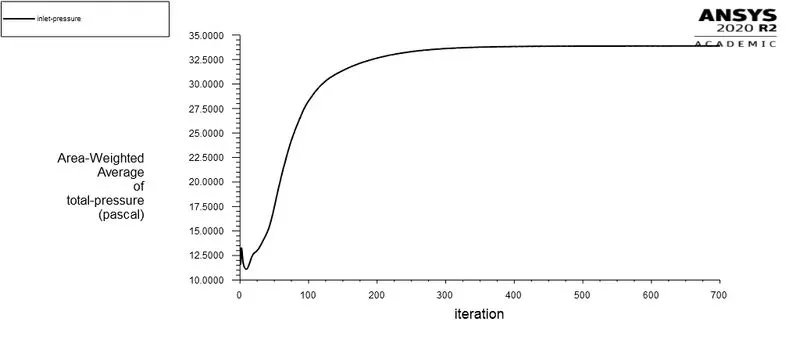
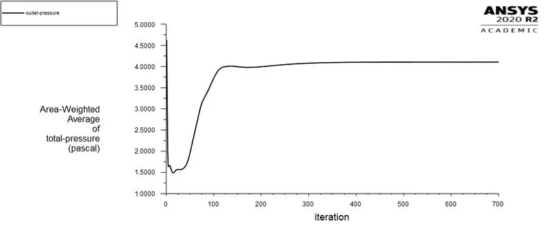
Total Pressure drop= Total inlet pressure - Total outlet pressure
= 33-4
= 29 Pascals.
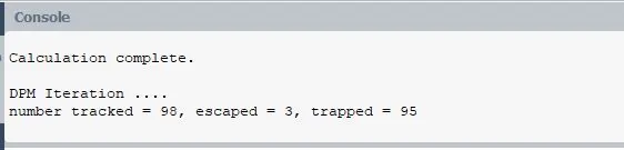
Seprator Efficiency= Number of particles trapped/ Number of particles tracked
= 95/98 *100= 97%
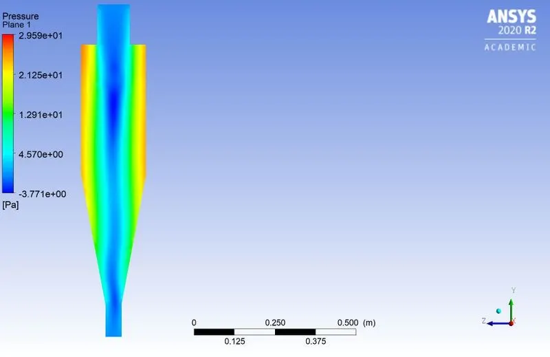
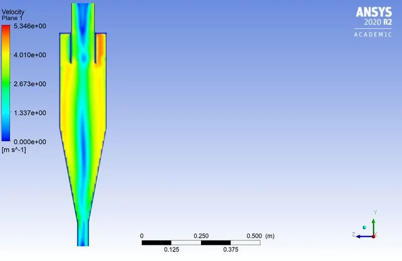
Figure11. Residual plots, inlet outlet total pressure, velocity and pressure contours (V3=3m/s)
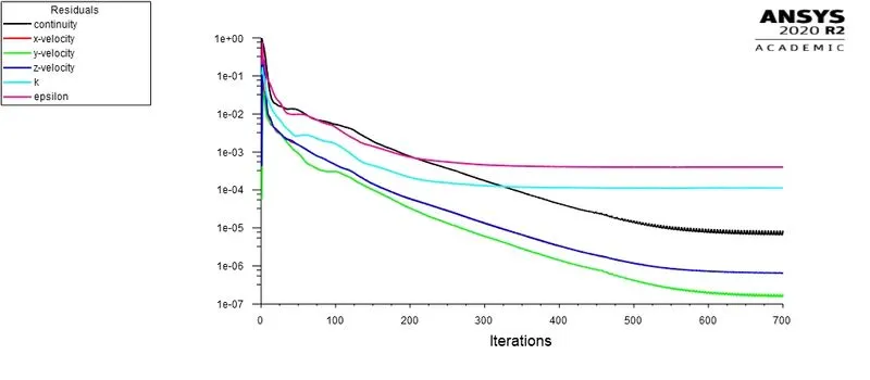
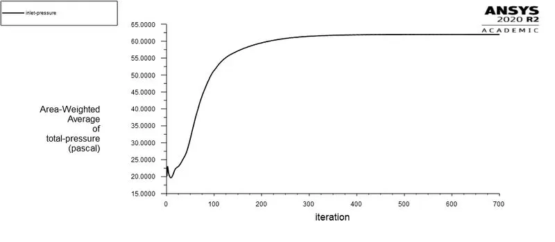
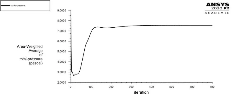
Total Pressure drop= Total inlet pressure - Total outlet pressure
= 60-7.5
= 52.5 Pascals.
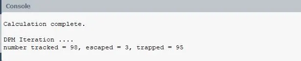
Seprator Efficiency= Number of particles trapped/ Number of particles tracked
= 95/98 *100= 97%
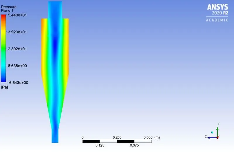
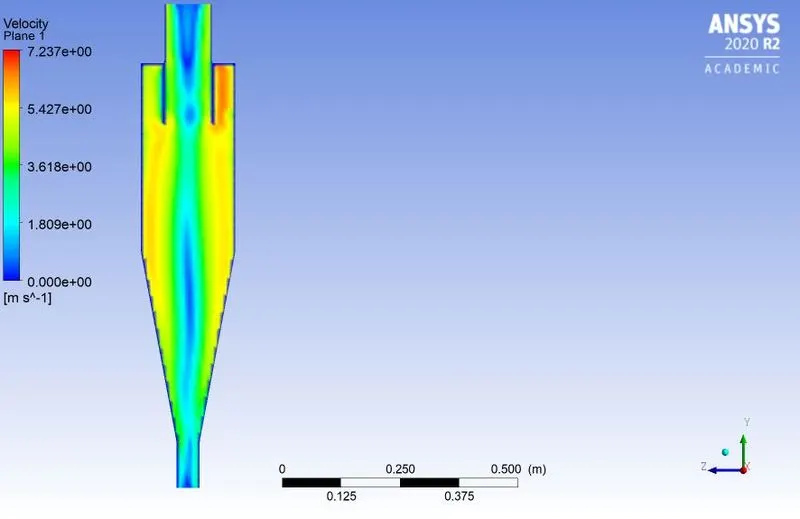
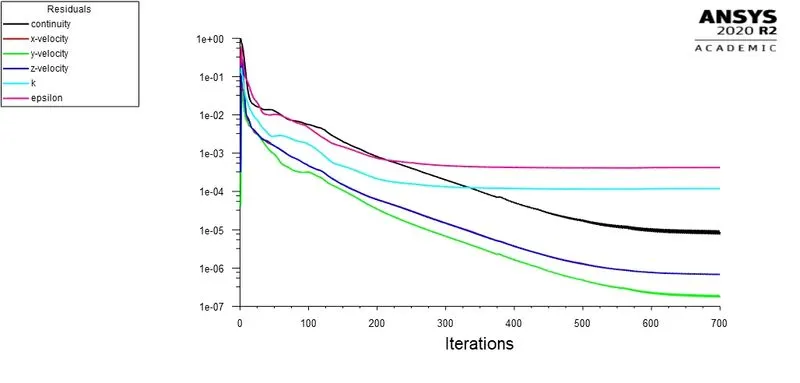
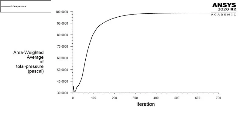
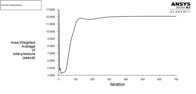
Total Pressure drop= Total inlet pressure - Total outlet pressure
= 98-12
= 86 Pascals.
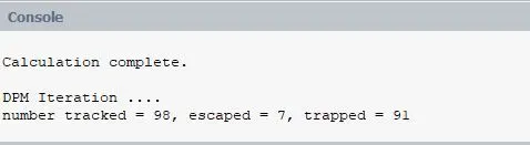
Seprator Efficiency= Number of particles trapped/ Number of particles tracked
= 91/98 *100= 93%
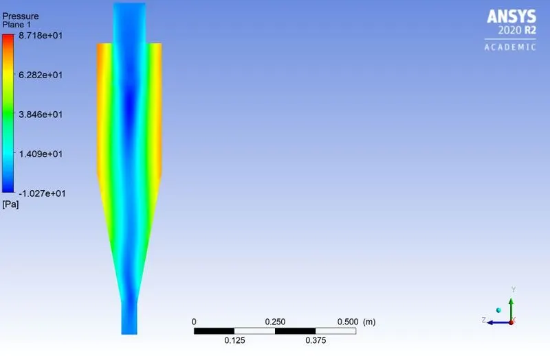
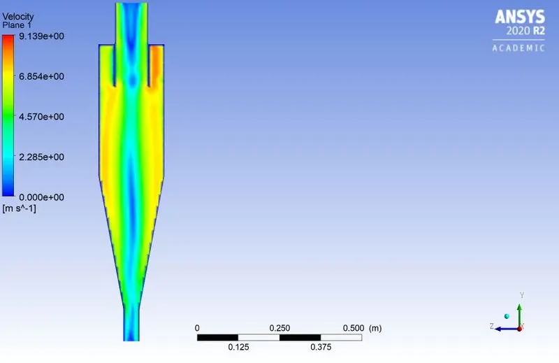
Figure 13. Residual plot, inlet, outlet total pressure, pressure and velocity contours (V5=5m/s)
| Case | Particle Diameter (Micrometer) | Velocity | Seprator efficiency | Total Pressure drop |
| Case-1 |
d1=1 d2=2 d3=3 d4=4 d5=5 |
V=3m/s |
E1=28.57% E2= 58.16% E3= 78.72% E4= 85.71% E5= 97% |
Pressure drop remains constant as velocity remains constant. |
| Case-2 |
V1=1 m/s V2=2m/s V3=3m/s V4=4 m/s V5=5m/s |
d=5 Micrometer |
E1=9.1% E2=37% E3=97% E4=97% E5=93% |
P1= 2.75 pascals P2=12.30 pascals P3=29 pascals P4=52.5 pascals P5=86 pascals |
5. Conclusion:
From the above obtained results the following conclusions are made
- The sepration efficiency of cyclone seprator primarly depends on diameter of particle and inlet velocity of flue gases.
- The pressure drop in cyclone seprator mainly depends on inlet velocity of the flue gases.
- The sepration efficiency of cyclone seprator increases with increase in the diameter of particle when inlet velocity of flow remains constant. While the pressure drop in cyclone seprator remains constant.
- The total pressure drop in cyclone seprator increases with increase in the inlet velocity when diameter of particle is kept constant.
- There exist an upper limitimg value for inlet velocity (4m/s) above which the seprator efficiency decreases with increase in the inlet velocity.
- High pressure regions are observed near the wall of the cyclone seprator.
- Higher velocity regions are observed at the inlet port of the cyclone seprator.