Creation of Multiple viewports, Scaling the drawing and setting in Template in AutoCad
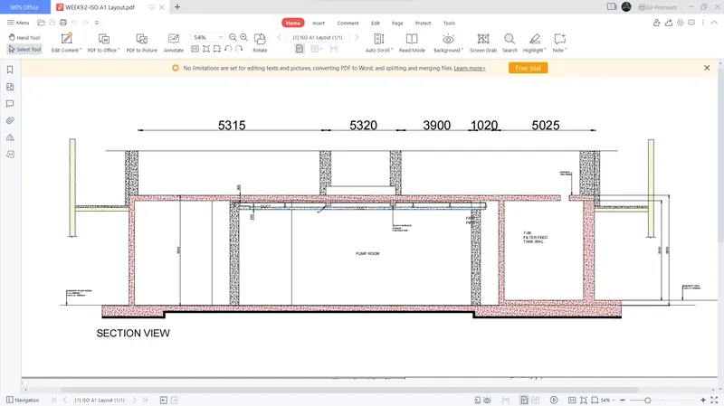
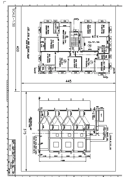
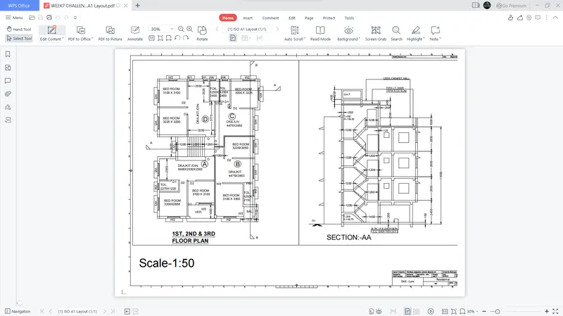
1. AIM- To create a layout of plan and section A in the project using the template Tutorial-mArch.dwt in a scale as given in the Figure.
INTRODUCTION-
- Layout plan-
- In architecture and building engineering, a floor plan is a drawing to scale, showing a view from above, of the relationships between rooms, spaces, traffic patterns, and other physical features at one level of a structure.
- Dimensions are usually drawn between the walls to specify room sizes and wall lengths.
- A scale diagram of the arrangement of rooms in one storey of a building.
- Floor plans make it easier to check if a space works for its purpose.
- A floor plan helps with any potential challenges, redesigning and functionality goals.
- This can help greatly with in depth planning and building stages.
- Floor plans highlight both the interior and outdoor of a space.
- A scale diagram of a room or suite of rooms viewed from above and used especially for planning effective use and arrangement of furnishings.
- Section plan-
- Section plan shows a view of a structure as though it had been sliced in half or cut along another imaginary plane.
- Section drawings are a specific type of drawing architects use to illustrate a building or portion of a building.
- A section is drawn from a vertical plane slicing through a building.
- This is as if you cut through a space vertically and stood directly in front looking straight at it.
- Sections are a common design drawing and technical architectural or engineering convention for graphic representation of architecture.
- Section drawings are orthographic projections.
- This means they are not drawn in perspective and there is no foreshortening.
- AutoCAD-
- AutoCAD stands for Computer-Aided Design.
- AutoCAD is software developed by the company Autodesk.
- It allows you to draw and edit digital 2D and 3D designs more quickly and easily than you could by hand.
- This software is used for designing and drafting.
- It is used for a number of applications like creating blueprints for buildings, bridges, etc.
- AutoCAD is 2D and 3D computer-aided drafting software application.
- AutoCAD software saves a huge time, saving time is equal to earn more income by more output, It is a simple enough software with the real user friendly interface, It is easy to grasp and it can provide you the basic exposure, It is very beneficial in designing 3D.
- Civil engineers design, construct, supervise, operate, and maintain large construction projects and systems, including roads, buildings, airports, tunnels, dams, bridges, and systems for water supply and sewage treatment.
- commands in autoCAD-
- Line- Start the Line command by clicking the Line button on the Draw panel on the Ribbon, or by entering L and then pressing Enter. Draw line segments by picking several random points. Terminate the command by pressing Enter, Esc, or the spacebar. Press Enter or the spacebar to repeat the Line command.
- Dimensions- You can select objects or points on objects to dimension, and then click to place the dimension line. When you hover over an object, the DIM command automatically generates a preview of a suitable dimension type to use. Supported dimension types include vertical, horizontal, and aligned linear dimensions.
- Text- Select text command from the Annotation menu of the Home tab of this software. We have two types of text command in auto cad. One is Multiline text, and the other is Single line text. You can use any one of the text commands according to your requirement.
- Fillet- Select the Fillet command from the ribbon panel, Or Type F on the command line or command prompt and press Enter. then Select the first object,Type R or Radius. Enter. Then Specify the radius of the Fillet and press Enter and Select the second object.
- Trim- Click Home tab Modify panel Trim. Find. Select the objects to serve as cutting edges. Press Enter when you finish selecting the cutting edges. Select the objects to trim and press Enter a second time when you finish selecting the objects to trim.
- Offset- We can offset any object through a point or at a specified distance. We can create as many parallel lines and curves with the help of the offset command.
- Layer command- The layer command is used to control and manage the drawings in AutoCAD for different purposes. It increases the display performance of the AutoCAD by hiding the portion of our drawing when needed. It also improves the visual complexity of the drawing.
- Hatch command-Go to the Draw panel on the Home tab>You will see a Hatch creation tab>Further specify the pattern on the Pattern panel>Choose your desired method>Pick Points or Select Boundary Objects>After filling the area, hit Enter to apply the hatch.
- Construction lines- Click Home tab Draw panel Construction Line> Specify a point to define the root of the construction line > Specify a second point through which the construction line should pass and enter.
- Layout template- At the Command prompt, enter layout. At the prompt, enter sa to save the current layout as a template. Enter the name of the layout you are saving. In the Create Drawing File dialog box, enter a name for the drawing template file you are creating.
Procedure:
- Sketch drawing as per given dimension
- I already sketched drawing
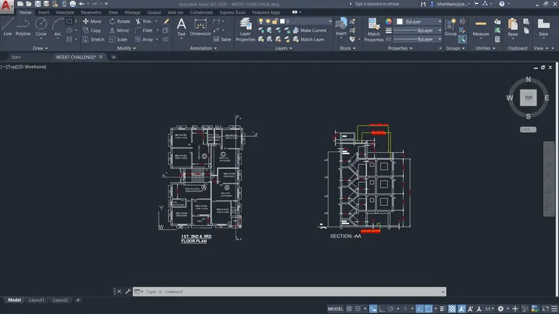
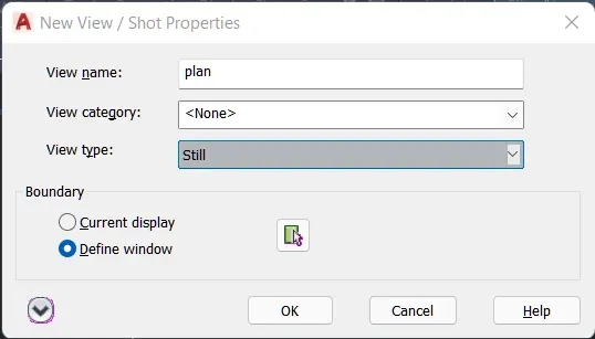
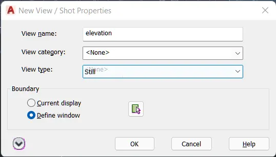
- Select view tab -> select new view tab > specify name > specify windows > press ok
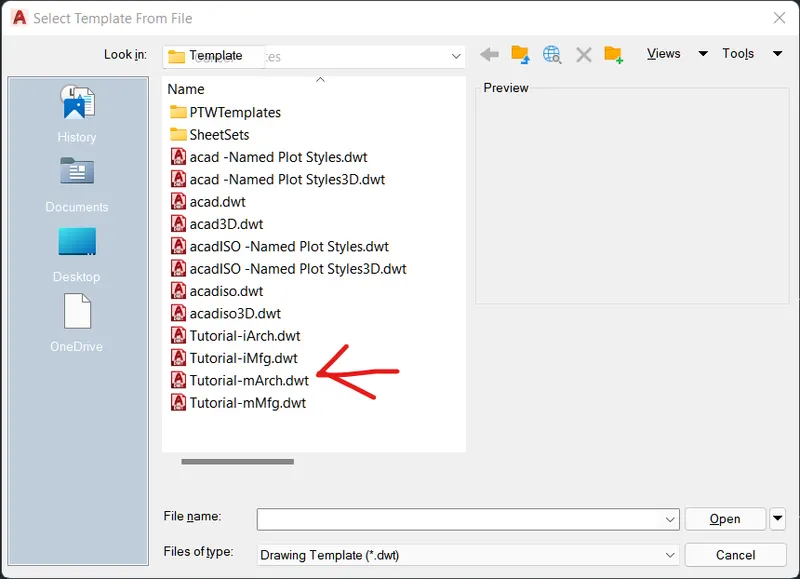
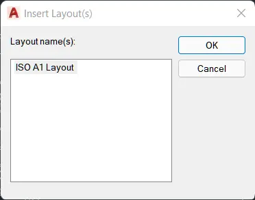
- select layout >template>select tutorial.mArch.dwt>press ok>insert layout >select isoA1 layout>press ok
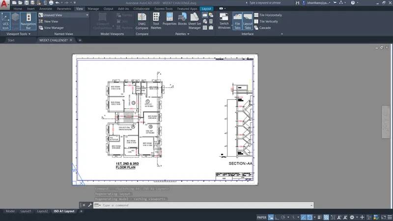
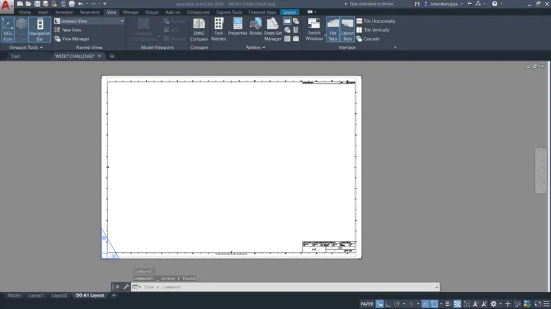
- select paper space>command ps> delect model space
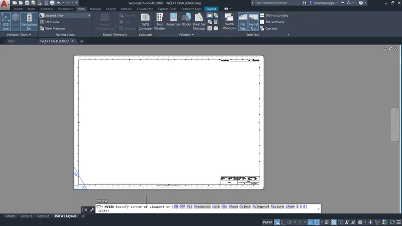
- select mulitiview command (mv)>select name>type plane/elevation>specify position > press ok

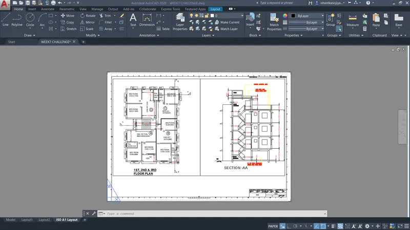
- Adjust size
- Select addit/double click on temp> edit information
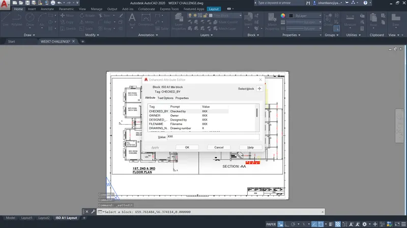
- fill information
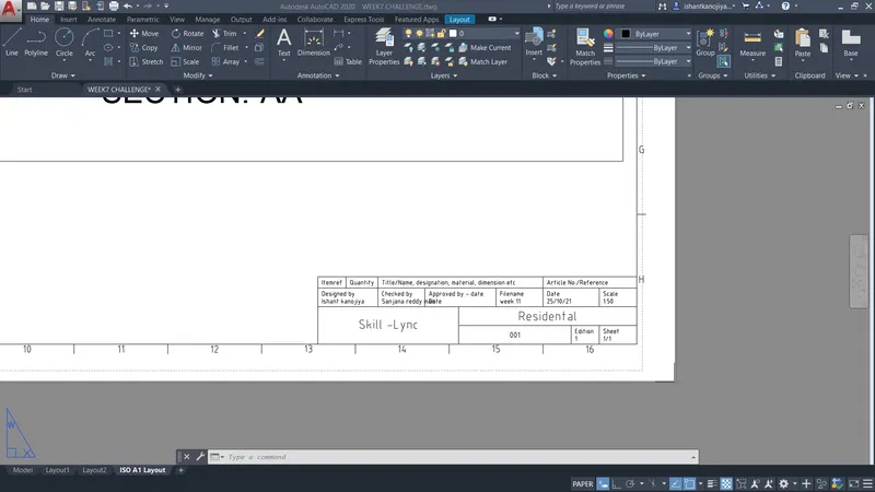
- select page setup manager > select layout > select modify
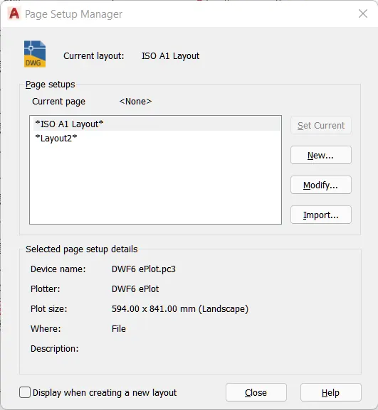
- page setup is open> give name> select paper size >select plooter name> select plot style table >press ok
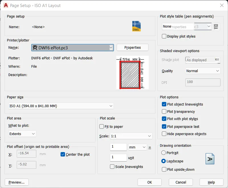
- preview image
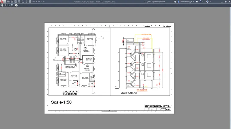
- press ok exit page setup command
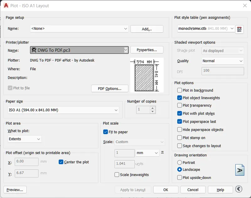
- select plot command > specify name >Specify printer name> select paper size> select fit to paper>select center the plot>select plot style table as monochrome.ctb>select quality > select landscape> press preview> it ok than press ok to plot the drawing
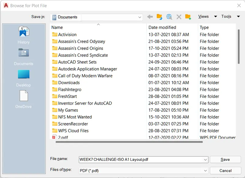
- save option is appear > specify location where you want to save>specify name > press ok
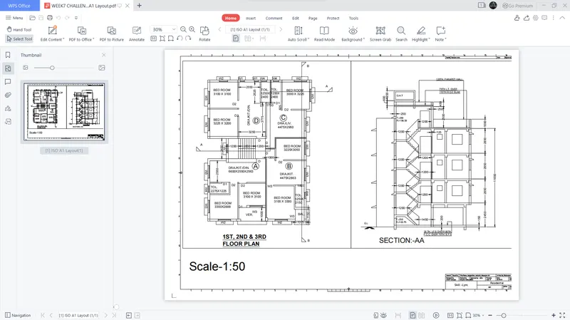
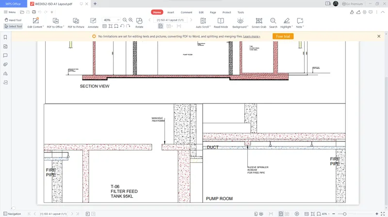
Result: File is converted into .dwg to .pdf
paper size is A1
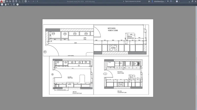
2. Aim: To create a layout of kitchen draw using a template on Autocad.
Introduction:
- AutoCAD-
- AutoCAD stands for Computer-Aided Design.
- AutoCAD is a software developed by the company Autodesk.
- It allows you to draw and edit digital 2D and 3D designs more quickly and easily than you could by hand.
- This software is used for designing and drafting.
- It is used for a number of applications like creating blueprints for buildings, bridges, etc.
- AutoCAD is a 2D and 3D computer-aided drafting software application.
- AutoCAD software saves a huge time, saving time is equal to earning more income by more output, It is a simple enough software with the real user-friendly interface, It is easy to grasp and it can provide you the basic exposure, It is very beneficial in designing 3D.
- Civil engineers design, construct, supervise, operate, and maintain large construction projects and systems, including roads, buildings, airports, tunnels, dams, bridges, and systems for water supply and sewage treatment.
- commands in AutoCAD-
- Line- Start the Line command by clicking the Line button on the Draw panel on the Ribbon, or by entering L and then pressing Enter. Draw line segments by picking several random points. Terminate the command by pressing Enter, Esc, or the spacebar. Press Enter or the spacebar to repeat the Line command.
- Dimensions- You can select objects or points on objects to dimension, and then click to place the dimension line. When you hover over an object, the DIM command automatically generates a preview of a suitable dimension type to use. Supported dimension types include vertical, horizontal, and aligned linear dimensions.
- Text- Select text command from the Annotation menu of the Home tab of this software. We have two types of text commands in auto cad. One is Multiline text, and the other is Single line text. You can use any one of the text commands according to your requirement.
- Fillet- Select the Fillet command from the ribbon panel, Or Type F on the command line or command prompt and press Enter. then select the first object, Type R or Radius. Enter. Then Specify the radius of the Fillet and press Enter and Select the second object.
- Trim- Click Home tab Modify panel Trim. Find. Select the objects to serve as cutting edges. Press Enter when you finish selecting the cutting edges. Select the objects to trim and press Enter a second time when you finish selecting the objects to trim.
- Offset- We can offset any object through a point or at a specified distance. We can create as many parallel lines and curves as with the help of the offset command.
- Layer command- The layer command is used to control and manage the drawings in AutoCAD for different purposes. It increases the display performance of the AutoCAD by hiding the portion of our drawing when needed. It also improves the visual complexity of the drawing.
- Hatch command-Go to the Draw panel on the Home tab>You will see a Hatch creation tab>Further specify the pattern on the Pattern panel>Choose your desired method>Pick Points or Select Boundary Objects>After filling the area, hit Enter to apply the hatch.
- Construction lines- Click Home tab Draw panel Construction Line> Specify a point to define the root of the construction line > Specify a second point through which the construction line should pass and enter.
- Layout template- At the Command prompt, enter layout. At the prompt, enter a to save the current layout as a template. Enter the name of the layout you are saving. In the Create Drawing File dialog box, enter a name for the drawing template file you are creating.
Procedure:
- Sketch drawing as per given dimension
- I already sketched drawing
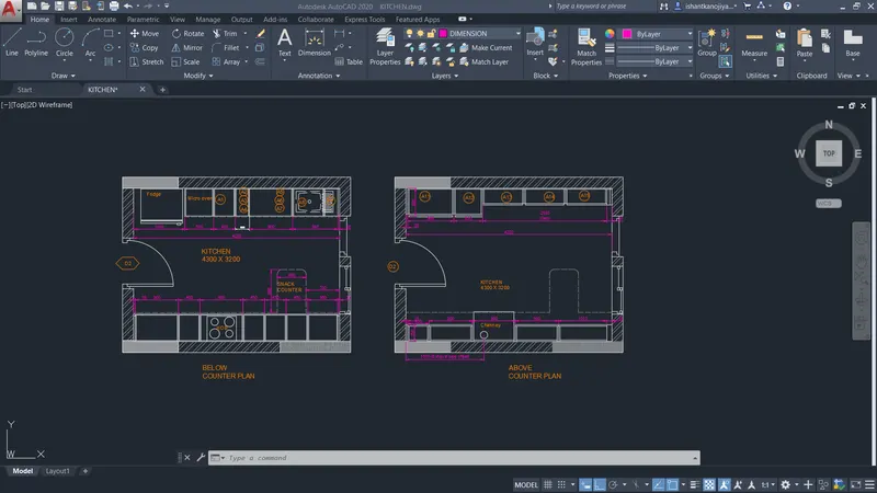
- select new view command> specify name> select drag to your area to view port> press ok
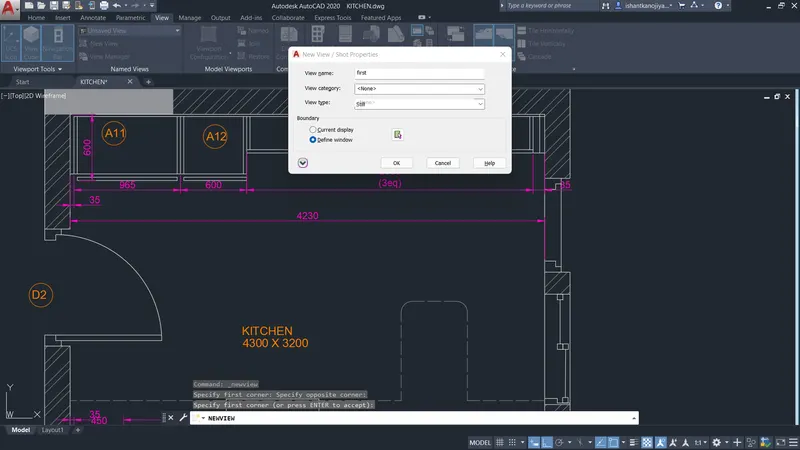
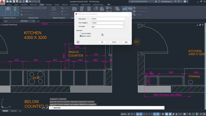
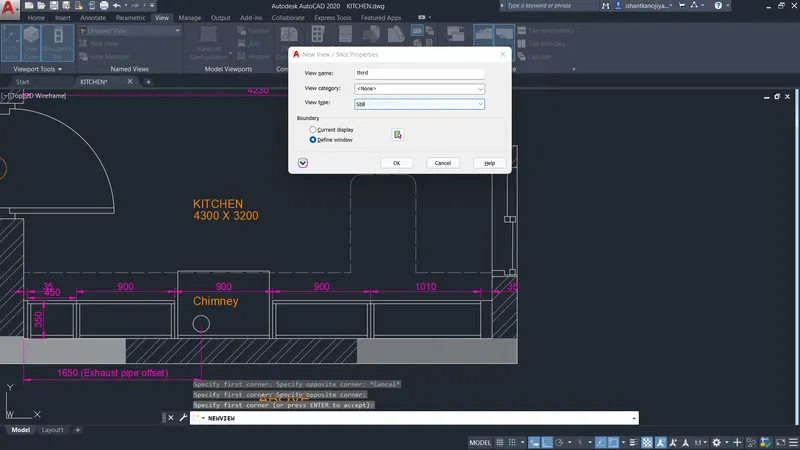
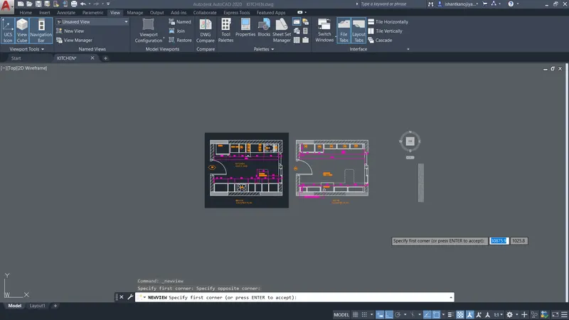
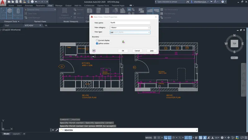
- select layout command> select template> press ok
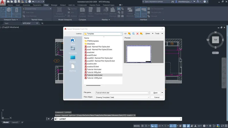
- Select ISOA1 layout > press ok
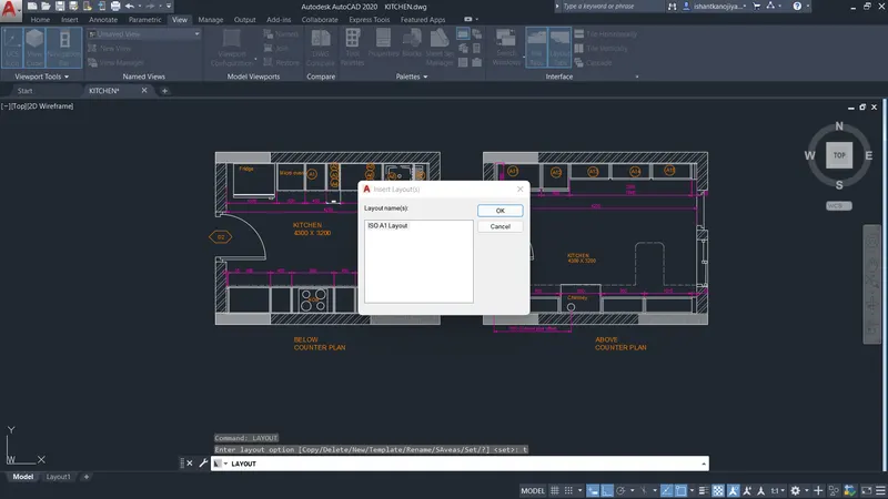
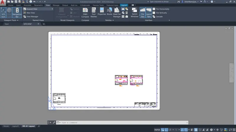
- select model space
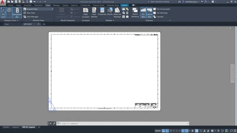
- select multiview command> select name option> give name of viewport> specify location> press ok

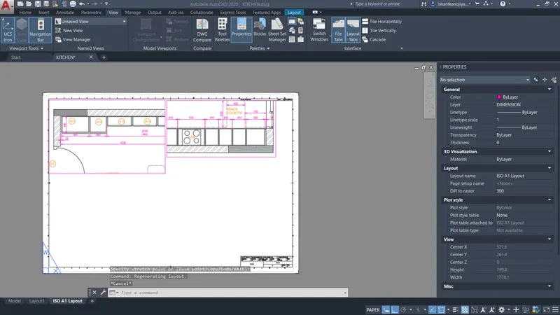
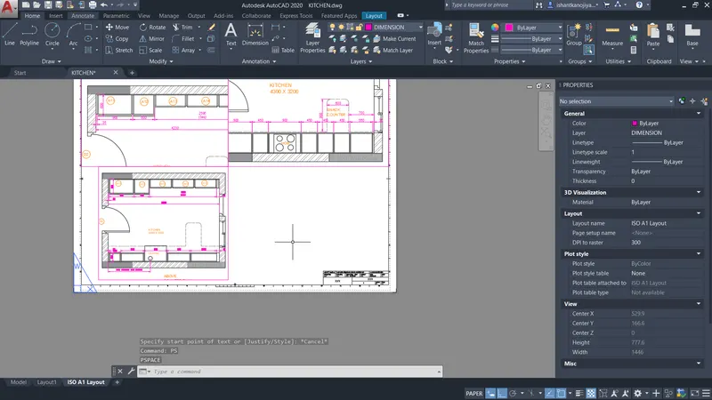
- I can delete template blocks because of space
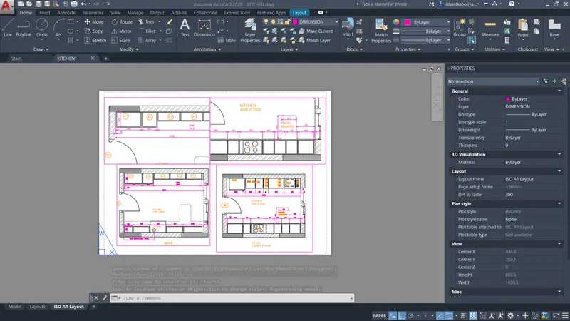
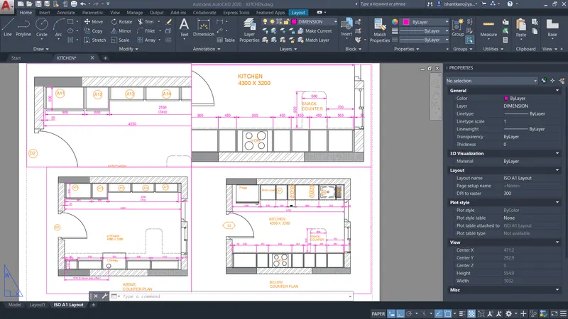
- adjust the viewport and lock the viewports
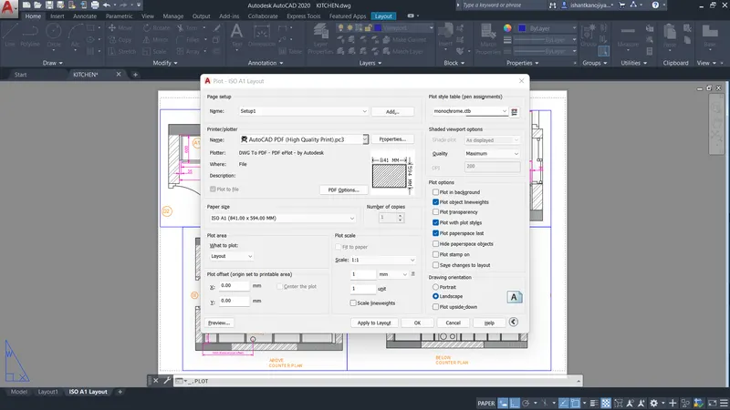
- select page setup manager>select name plotter> select page size> select style table> press ok
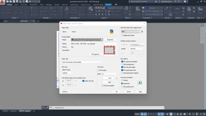
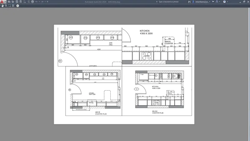
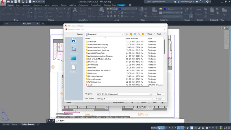
- plot the drawing
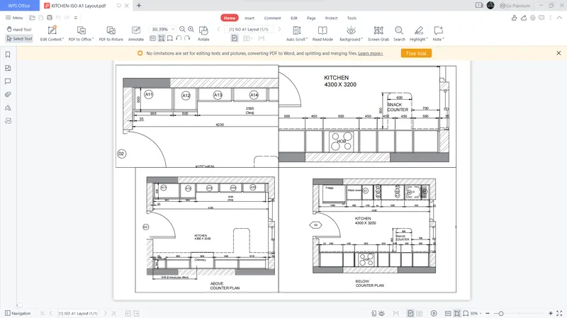
Result:
3. AIM: To create a layout of the section using a given scale in Autocad
Introduction-
- AutoCAD-
- AutoCAD stands for Computer-Aided Design.
- AutoCAD is a software developed by the company Autodesk.
- It allows you to draw and edit digital 2D and 3D designs more quickly and easily than you could by hand.
- This software is used for designing and drafting.
- It is used for a number of applications like creating blueprints for buildings, bridges, etc.
- AutoCAD is a 2D and 3D computer-aided drafting software application.
- AutoCAD software saves a huge time, saving time is equal to earning more income by more output, It is a simple enough software with the real user-friendly interface, It is easy to grasp and it can provide you the basic exposure, It is very beneficial in designing 3D.
- Civil engineers design, construct, supervise, operate, and maintain large construction projects and systems, including roads, buildings, airports, tunnels, dams, bridges, and systems for water supply and sewage treatment.
- commands in AutoCAD-
- Line- Start the Line command by clicking the Line button on the Draw panel on the Ribbon, or by entering L and then pressing Enter. Draw line segments by picking several random points. Terminate the command by pressing Enter, Esc, or the spacebar. Press Enter or the spacebar to repeat the Line command.
- Dimensions- You can select objects or points on objects to dimension, and then click to place the dimension line. When you hover over an object, the DIM command automatically generates a preview of a suitable dimension type to use. Supported dimension types include vertical, horizontal, and aligned linear dimensions.
- Text- Select text command from the Annotation menu of the Home tab of this software. We have two types of text commands in auto cad. One is Multiline text, and the other is Single line text. You can use any one of the text commands according to your requirement.
- Fillet- Select the Fillet command from the ribbon panel, Or Type F on the command line or command prompt and press Enter. then select the first object, Type R or Radius. Enter. Then Specify the radius of the Fillet and press Enter and Select the second object.
- Trim- Click Home tab Modify panel Trim. Find. Select the objects to serve as cutting edges. Press Enter when you finish selecting the cutting edges. Select the objects to trim and press Enter a second time when you finish selecting the objects to trim.
- Offset- We can offset any object through a point or at a specified distance. We can create as many parallel lines and curves as with the help of the offset command.
- Layer command- The layer command is used to control and manage the drawings in AutoCAD for different purposes. It increases the display performance of the AutoCAD by hiding the portion of our drawing when needed. It also improves the visual complexity of the drawing.
- Hatch command-Go to the Draw panel on the Home tab>You will see a Hatch creation tab>Further specify the pattern on the Pattern panel>Choose your desired method>Pick Points or Select Boundary Objects>After filling the area, hit Enter to apply the hatch.
- Construction lines- Click Home tab Draw panel Construction Line> Specify a point to define the root of the construction line > Specify a second point through which the construction line should pass and enter.
- Layout template- At the Command prompt, enter layout. At the prompt, enter a to save the current layout as a template. Enter the name of the layout you are saving. In the Create Drawing File dialog box, enter a name for the drawing template file you are creating.
Procedure-
- Sketch drawing as per given dimension
- I already sketched drawing
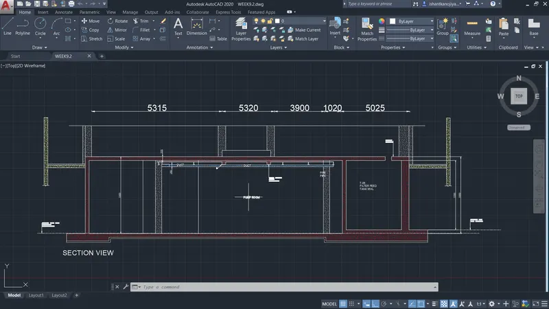
- select layout command> select template option> select template> select layout> press ok
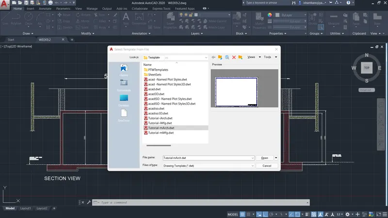
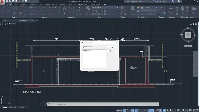
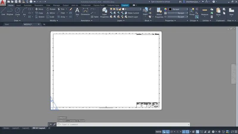
- select new viewport command> specify name > select area to view by drag the cursor> press ok
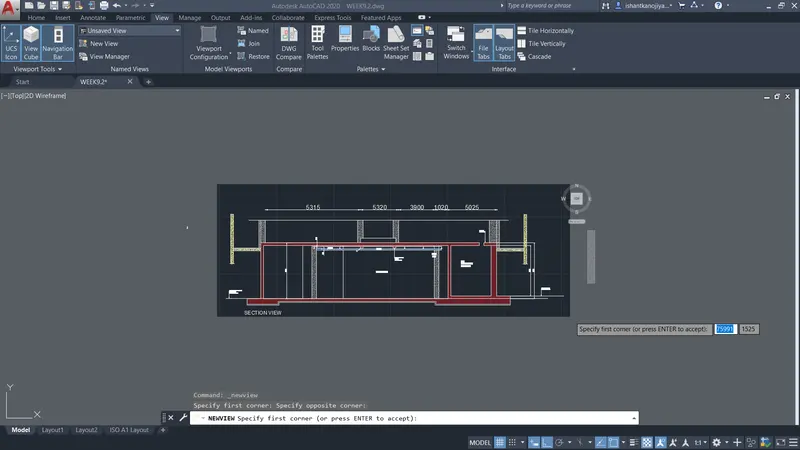
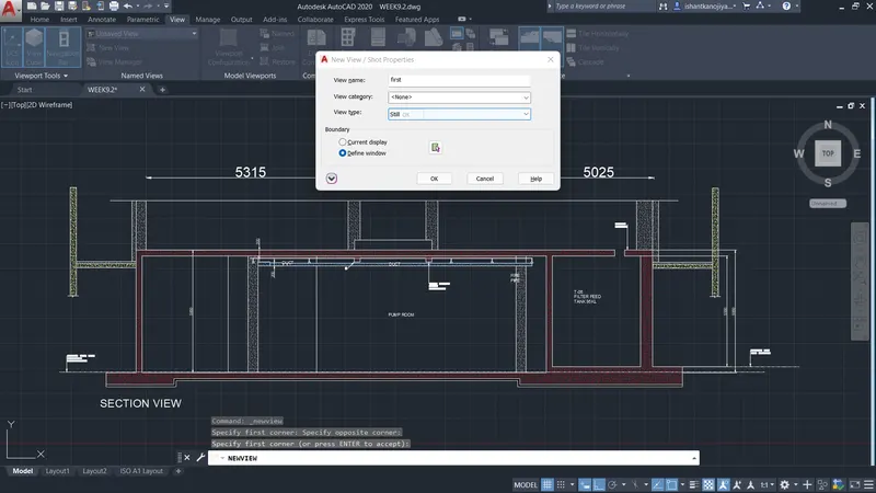
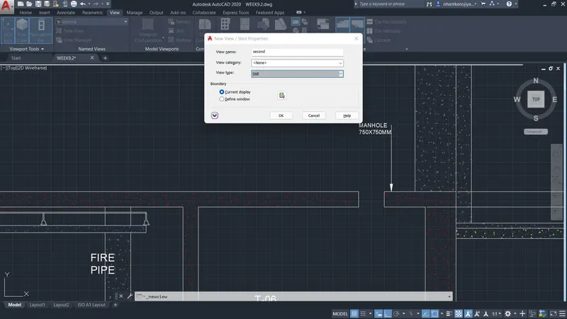
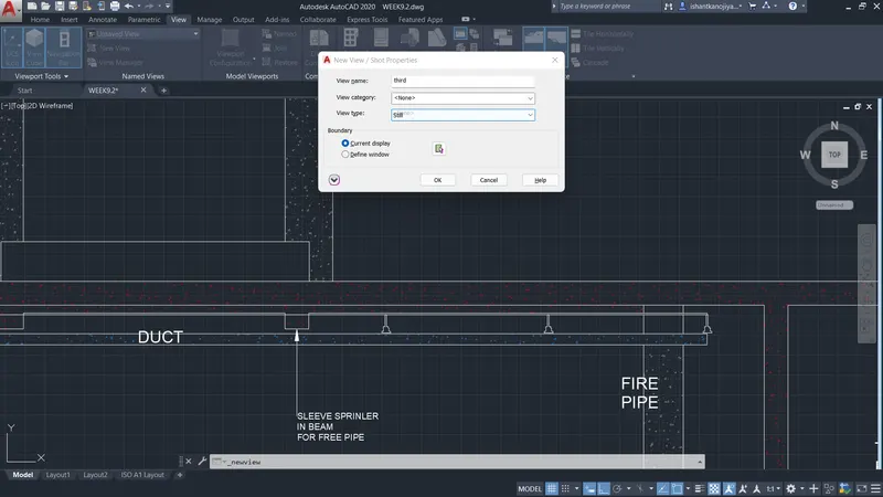
- Select multiview command> select name option> give name> specify size and location where you place> press enter
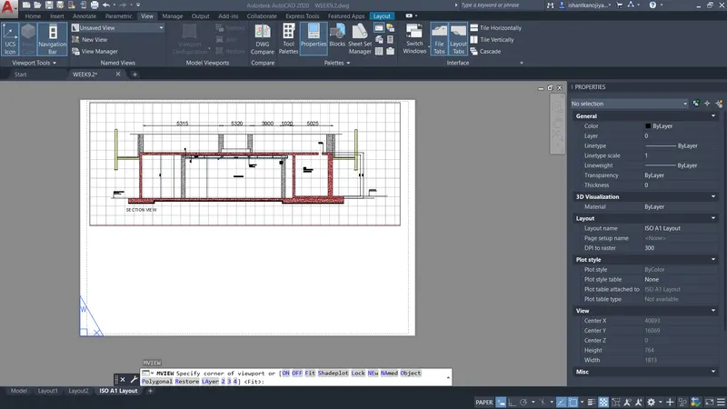
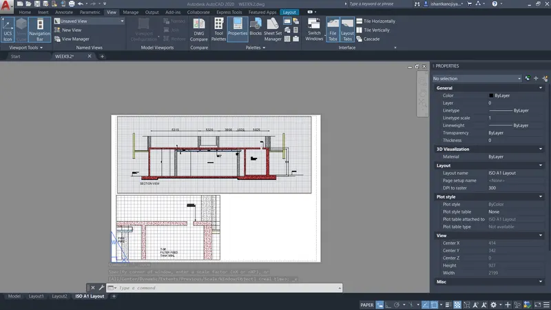
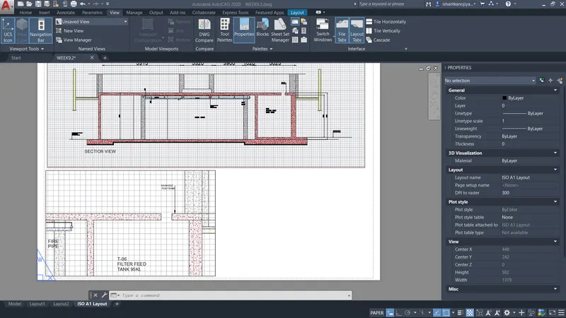
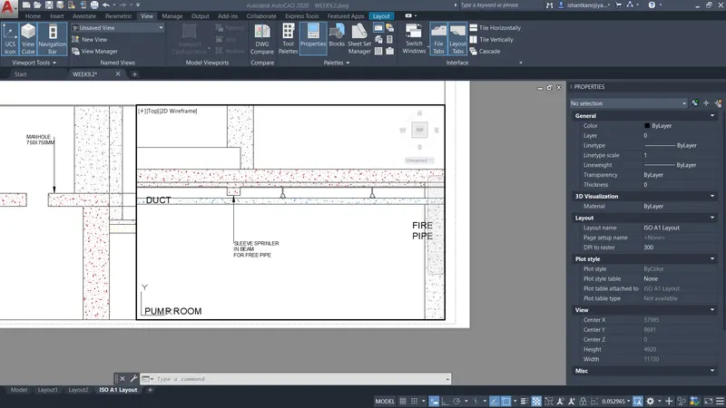
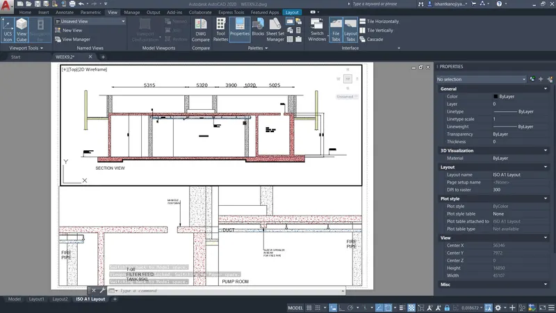
- select page setup manager> select layout > select modify
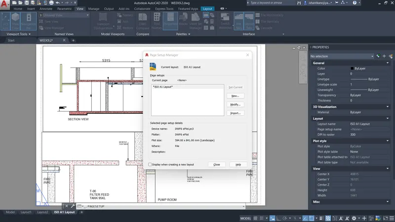
- select plooter name> select page size > select what is plot> select plot style table> press ok
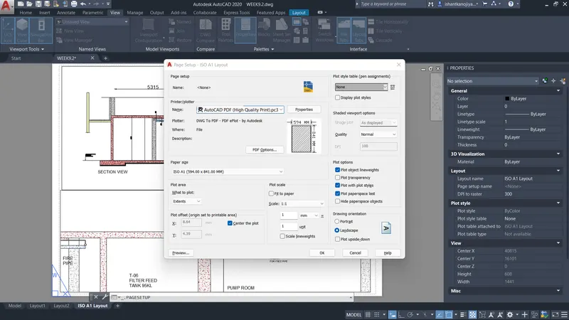
- preview
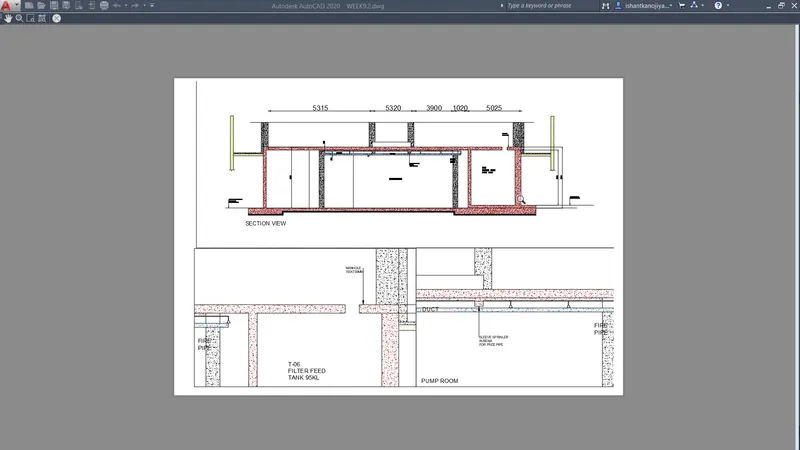
- select plot command> every thing is set > specify name> press ok
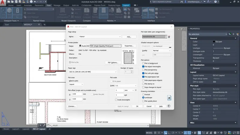
- select preview
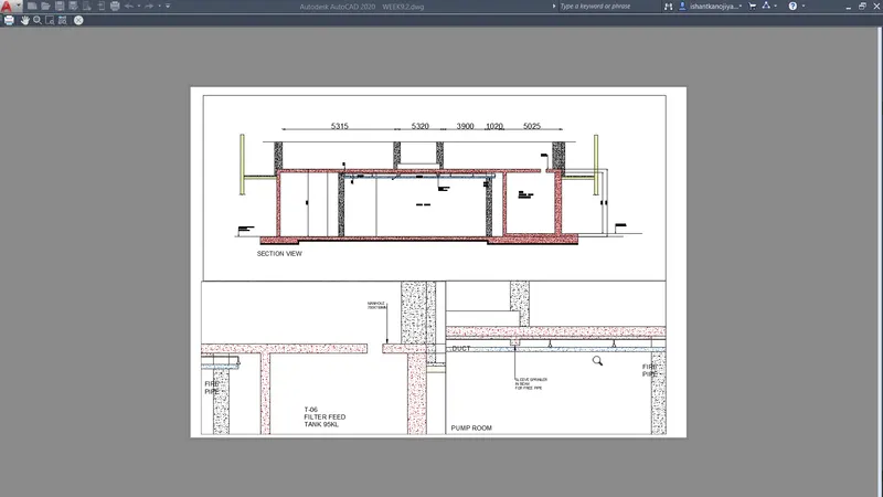
- save as file name and specify location
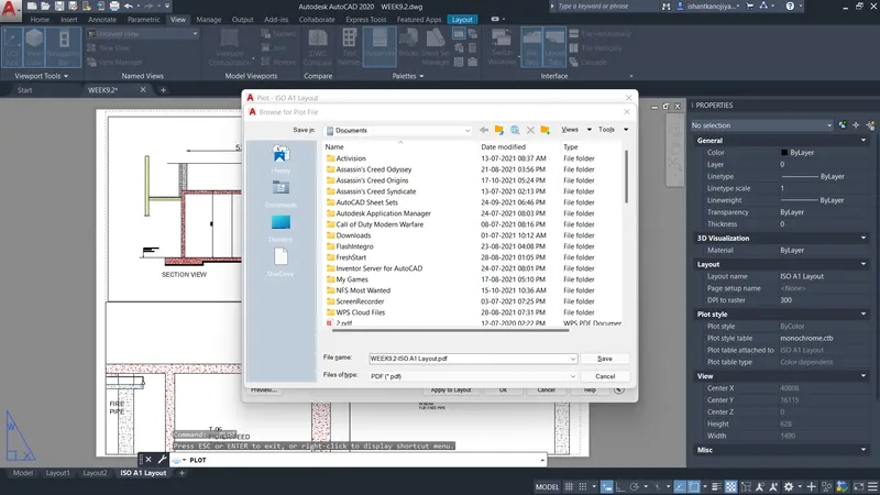
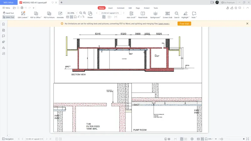
Result