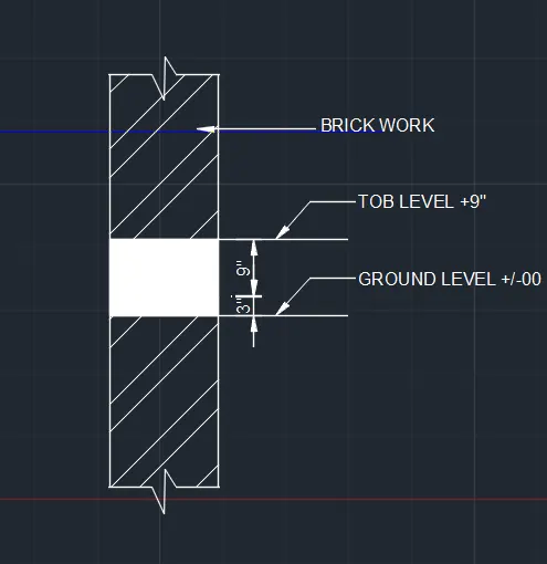
Creation of Column Schedule and Drawing Template using AutoCad
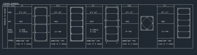
AIM & INTRODUCTION: To create a column schedule as shown in the figure by using auto cad .
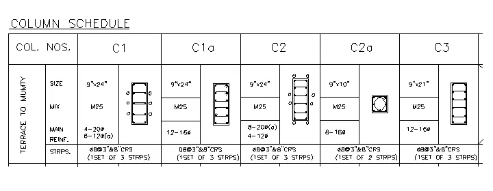
Procedure:
- Get in to a new drawing file and set start up settings in to Imprerical
- Set limits as 10',10' by using LI command
- Set the text height as 8" and text style as Romans.SHX by using ST command
- Set th units in architecture
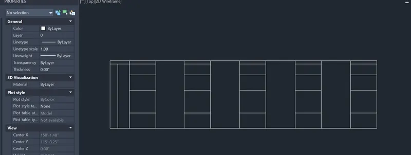
Step:1 Create a rectangle as per assumerd size which depends upon sizes of column and text
- Type rectangle in command prompt > Specify the dimensions
- By using line command and offset command divide the rectangle in to 5 parts X direction and four parts in Y direction
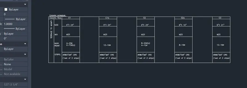
- Type the text snown in figure by using DTEXT command \
- Text can be rotated by using rotation command
STEP:2 Draw the column details as[er dimensions
- Type rectangle in Command prompt : RECTANG
- Specify other corner point or [Area/Dimensions/Rotation]:d
- Specify length for rectangles : 9"
- Specify width for rectangles : 24"
- Command: OFFSET
- Specify offset distance : 0.4"
- Select the rectangle and in side of the rectangle
- Create a circle by using circle command and select TTR option
- Select the lines of first corner as tangents and type radius as :0.39" as (10mm radius)
- Mirror the circle at opposite & vertically downwards direction with refrance the mid line of inner rectangle
- Specify the circle of radius 0.23" at a 3 points of 6" equal distance
- Mirror the circle at opposite & vertically downwards direction with refrance the mid line of inner rectangle
- Extensions of circle can be provided by line command
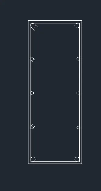
- Type explode command to explode inner rectangle and copy the line at qadrents with copy command of the circle per figure given
- By trim command trim the extension lines or by using fillet command by radius of the circle
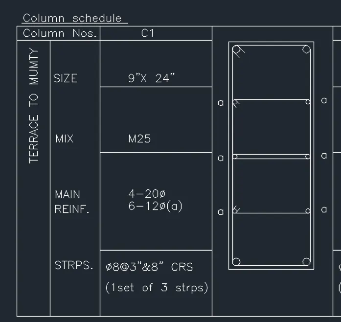
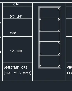
FOR C1 a:
- Type rectangle in Command prompt : RECTANG
- Specify other corner point or [Area/Dimensions/Rotation]:d
- Specify length for rectangles : 9"
- Specify width for rectangles : 24"
- Command: OFFSET
- Specify offset distance : 0.4"
- Select the rectangle and in side of the rectangle
- Create a circle by using circle command and select TTR option
- Select the lines of first corner as tangents and type radius as :0.314" as (8 mm radius)
- Explode the offset rectangle and divide in to 5 equal parts by divide command
- copy the circle at the divided length
- Mirror the circle by using MI command at opposite & vertically downwards direction with refrance the mid line of inner rectangle.
- Offset the lines at quadrents of the circles with offset command
- Fillet the corners with radius.
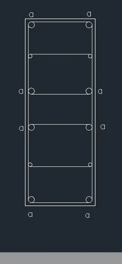
FOR C2:
- Type rectangle in Command prompt : RECTANG
- Specify other corner point or [Area/Dimensions/Rotation]:d
- Specify length for rectangles : 9"
- Specify width for rectangles : 24"
- Command: OFFSET
- Specify offset distance : 0.4"
- Select the rectangle and in side of the rectangle
- Explode the inner rectangle
- Divide in to 5 parts of the inner vertical line and copy the base line of inner rectangle at 5 parts of rectangle
- Draw the circle with TTR method of 0.39" at the corners of the inner rectangle
- and 0.23" at the remaining corners
- Use trim command for removing extra lines .
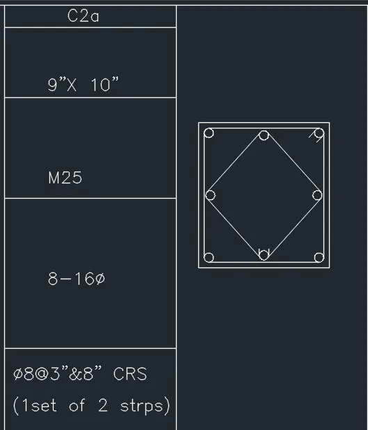
FOR C2a:
- Type rectangle in Command prompt : RECTANG
- Specify other corner point or [Area/Dimensions/Rotation]:d
- Specify length for rectangles : 9"
- Specify width for rectangles : 10"
- Command: OFFSET
- Specify offset distance : 0.4"
- Select the rectangle and in side of the rectangle
- Draw a line joining to all mid point of offset rectangle
- Using circle command with radius 0.314" make a circle by TTR option for all corners at rectangle and rhombus
- Use trim command for removing extra lines.
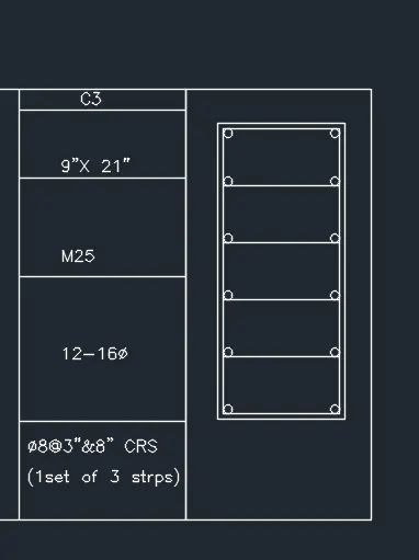
FOR C3:
- Type ‘rec’ or rectangle in the command prompt
- Specify other corner point or [ Area: Dimension: Rotation]: D
- Specify length for rectangle: Type 9” and press enter
- Specify width for rectangle: Type 21” and press enter
- Offset the rectangle at 0.4"
- Expolde the inner rectangle by explode command.
- Divide in to 5 parts by Divide command
- copy the base line of inner rectangle in to 5 points
- Draw the circle by usiong circle command with TTR option
- Select the corner lines as the tangents and enter radius 0.314".
Result:
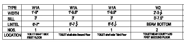
AIM & INTRODUCTION: To create a window schedule given in the figures by using Auto Cad.
Window schedule:
Procedure:
Open Drawing file
Set the units (Feet and inches)
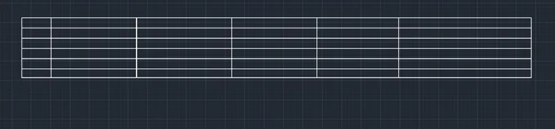
Step 1: Creating Table using Rectangle
- Type RECTANGLE command in the command box and press enter
- Specify the first point on the screen then second point
- Explode with explode command
- And divide in to six parts from vertical and horizontal direction using divide command.
- set text size 8" and texty style in roamns.SHX by using ST command.
- Type the text given in schedule by using text command Dtext
- For example : Dtext > rotation :0> enter text >type
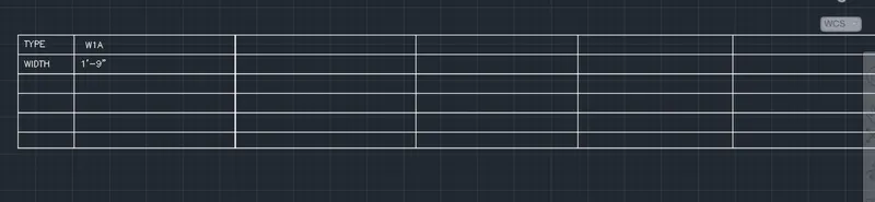
- Repete the above command to fill the text in table
Result:

Open Drawing file
Set the units (Feet and inches)
Set the text style as Romans.SHX and text height as 8"
Step 1: Creating Table using Rectangle
- Type RECTANGLE command in the command box and press enter
- Specify the first point on the screen then second point
- Explode the rectangle with explode command.
- type note text with multi text command
- make cells in rectalgle by using line command

- Type the text given in schedule by using text command DText.
Result:

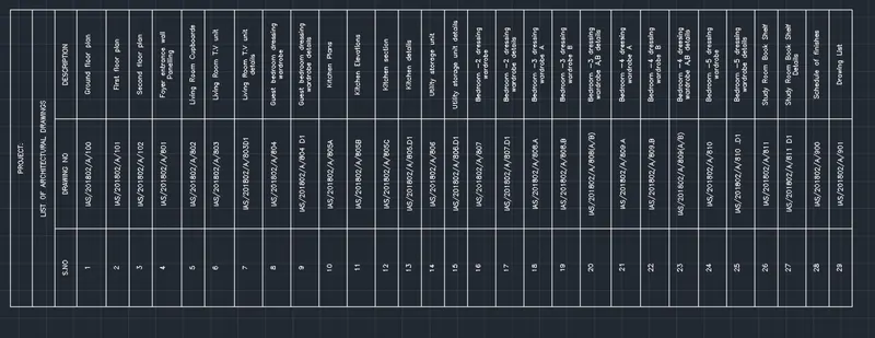
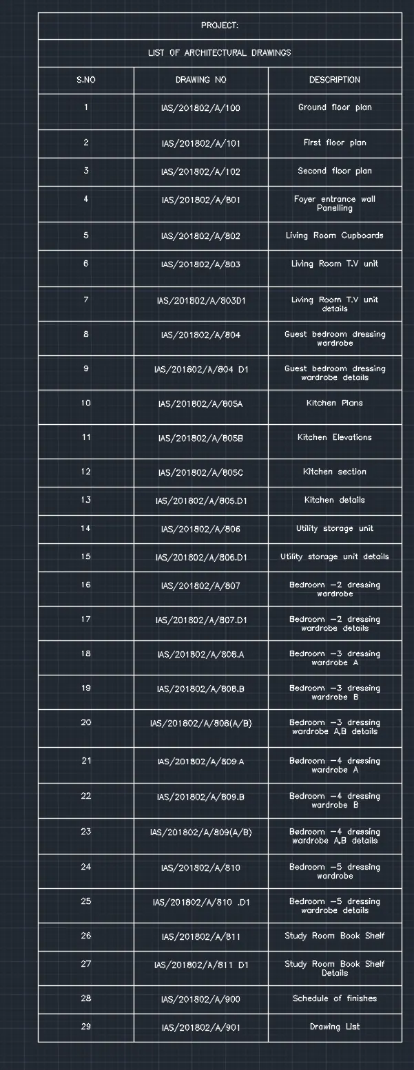
AIM & INTRODUCTION: To create the list of drawing schedule by using AUTOCAD as shown in the figure.
Procedure:
- Open Drawing file
- Set the units (Feet and inches)
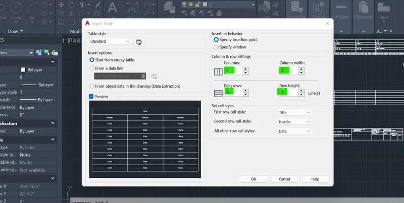
- Type TABLE command in command prompt
- sET NUMBER OF COLUMNS 3
- COLUMN WIDTH 1'
- DATA ROW : 31
- ROW HEIGHT :1
- CLICK OK
- Specify the starting point
- Type the text in cells
Result:
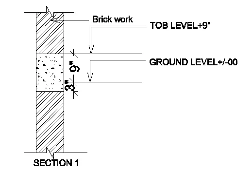
AIM & INTRODUCTION: To create the Beam detail as shown in the figure by using AUTO CAD and provide text wherever given.
Procedure:
- Get in to a new drawing file and set start up settings in to Imprerical
- Set limits as 10',10' by using LI command
- Set the text height as 8" and text style as Romans.SHX by using ST command
- Set th units in architecture
Step to follow:
- Type a RECTANGLE command in command prompt
- specify first poinrt
- specify dimension as 1' ,10'
- at the middle of rectangle join with horizontal line by using LINE command
- Using OFFSET command make 3" offset above the horizontal line
- and 9" to the last off set line
- Type break line command to draw the break line symbol on top and botttom side of figure
- Apply hatch by using hatch Command and select the closed area to hatch
- Give a dimensions by dimension linear command
- Provide text by LEADER command
Result: