Creation of Column Schedule and Drawing Template using AutoCad
1)
AIM : To Create a Coloumn Shedule as shown in the figure
Procedure
Step 1:
- Open AutoCAD and enter UN(Units Command) in command box and select type as engineering and precision as 0'-0.000''
- Select line command and draw a line of 84' in X axis and a line of 21' in Y axis and complete bigger rectangular
- Then Select the offset command and enter offset as 7' in X-axis,Give offests 11 times in X-axis as 7'
- Again Select the offset command and fromtop line give offset of 4'in the Y-axis and again offset of 3'from the bottom line of the table
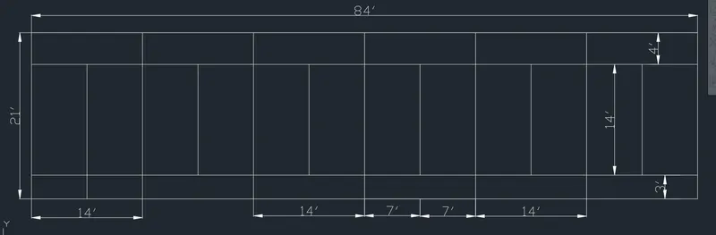
- Select the text command fro the ribbon and select single line text,Specify the text height as 8'' and angle o test as 90 degrees and enter the text as terrace to muty,the text will appear in the desired angle
- Again,Select the text command ow select multiline text drag the cursor in each of the row and coloumn and enter all the text in the table
Steps for drawing the coloumns
- The size of coloumn is C1 is 9'X24'' create a rectangle of size 9''X24'' i.e.., 2 '
- Select offset command and enter the value offset as 0.5 a similar rectangle in the original rectangle will be draw
- Now select the circle command and in that select tan tan radius and by selecting both corner lines enter the value of radius as 0.5
- Draw all circles in the 4 corners of the inner rectangle
- Now select the fillit command an fillit the edges as radius an enter the rdius as 0.5
- Now again select the circle command and select the two-point circle and draw the circle where the geometry is divide in parts
- Draw the coloumns C1a,C2a,C3 i the same manner
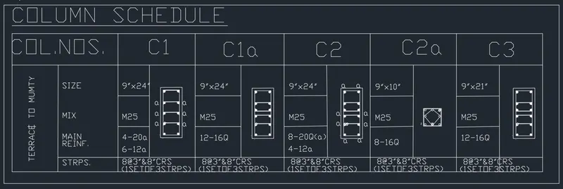
RESULT: Create a column schedule with the help of lines. Also, insert text with the help of Dtext command or Single Line text.
2)
AIM: To Create a Window schedule
PROCEDURE
Steps for drawing a schedule
- Open AutoCAD and enter UN(Units Command) in command box and select type as engineering and precision as 0'-0.000''
- Select the line command and draw a line of 75''(6'-3'') in X axis and aline of 24''(2') in Y axis and complete bigger rectangle
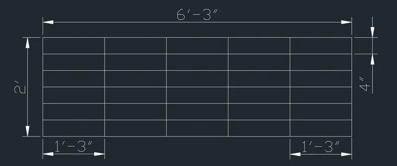
- Then select the offset command and from line give offset of 4' in the Y axis,Give such 4 offsets in the Y directions
- Now select the text command and in the text select the option as multiline text and drag it in each of the row and coloumn and enter the text
- In this way fill the entire table by using multiline text option
- Keep the size of text in between 1.5'' to 3'' that is the height of the text
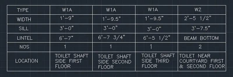
Result: Window Schedule is created
3)
AIM : To create line templaet
Procedure
- Select line command and draw a line of 150' in X axis and line of 20' in Y axis and complete bigger rectangle
- Select the offset command and enter offset as 50' in X axis, Give offsets 2 times in the X axis as 50'
- Select the offset command and from the line give offset of 4' in the Y axis,Give such 4 offsets in the Y axis
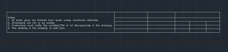
- Enter the offset command and in the right most art of table enter an offset of 12'-6'',Give such 3 offsets
- Now,select the text command and in the text select the option as multiline text and drag it in each of the row and coloumn and enter the text
- keep the size of text in between 8.5'' to 11.5'' that is the height of the text
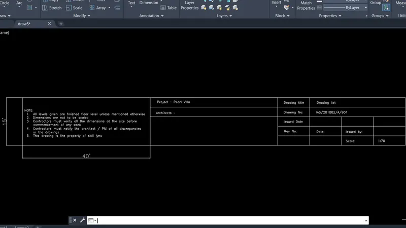
RESULT:Line templaet is created
4)
AIM: To create the list of drawing schedule table
Procedure:
- Open AutoCAD and enter UN( Units Command) in command box and select type as engineering precision as 0'-0.000''
- Select line command and draw a line of 135''(11'3'') i X axis and draw X line of in Y axis
- Select the offset command and enter offset as 10'',then 40''(3'4'') then 85''(7'-1'') in X axis
- Select the offset command and from line give offset of 4'',5'',4'' in the Y axis give such 28 offsets in the Y axis
- Trim the unwanted lines and draw the table as required
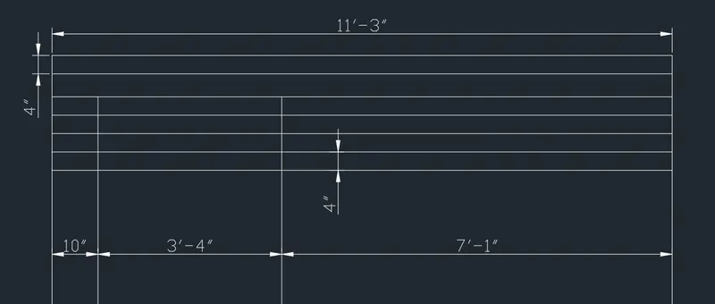
- Select the text xommand and in the text select the option as multiline text and drag it in each of the row and coloumn and enter the text
- Keep the size of text in between 1.5'' to 2.5'' that is the height of the text
- In this way fill the entire table by using, multiline text option
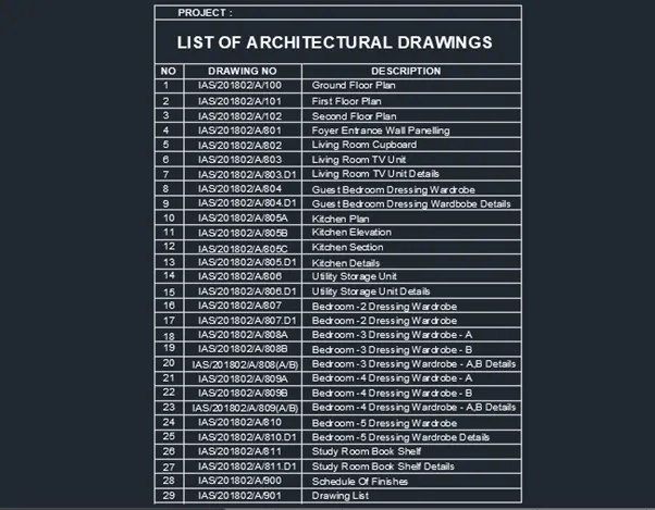
RESULT: List of drawing schedule table is drawn
5)
AIM: To create a beam detail
Procedure
- Open AutoCAD and enter UN(Units Command) in command box and select type as engineering precision as 0'-0.000''
- Select the Line command and draw a line of 9'' in X axis anda line of 5' in Y axis
- Select the offset command and enter offset as 2'-2.4'' in X axis from the bottom line of the beam cross section
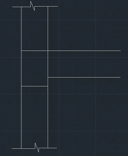
- Again enter an offset f 12'' from the below line in the upword direction
- Enter hatch in command box and go to settings in that select pattern and chose pattern as ANS132
- choose the scale of hatch as 0.35 and hatch the upper and lower part of beam cross section
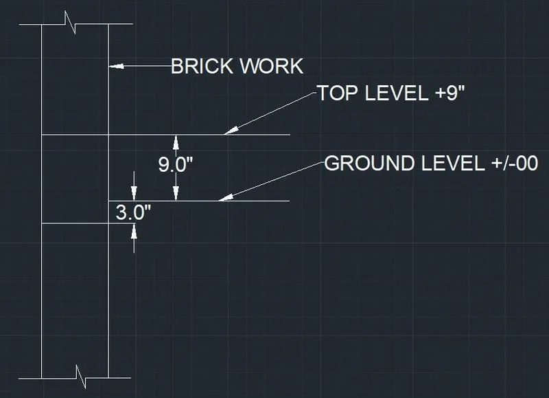
- Again by selecting hatch command and chooseas type ISO and choose AIR conc type and hatch the middle part of beam as concrete
- By using the dimenssion tool give the dimenssions to the beam section
- Select text and multiline text and drag the text where required to the desired scale according to the size of the drawing required
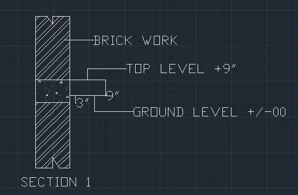
RESULT: created a beam detail is drawn