Creating various 3D Models like Furniture, Footing, Girder, Column drop with panel and Gable Wall in AutoCad
1. Create a 3D Furniture element as shown in the Figure. Assume dimensions which are missing.
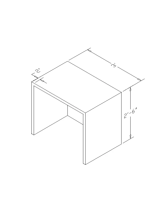
AIM- CREATE THE 3D MODEL OF FURNITURE ELEMENT SHOWN IN THE FIGURE.
INTRODUCTION-
AutoCAD-
- AutoCAD stands for Computer-Aided Design.
- AutoCAD is software developed by the company Autodesk.
- It allows you to draw and edit digital 2D and 3D designs more quickly and easily than you could by hand.
- This software is used for designing and drafting.
- It is used for a number of applications like creating blueprints for buildings, bridges, etc.
- AutoCAD is 2D and 3D computer aided drafting software application.
- AutoCAD software saves a huge time, saving time is equal to earn more income by more output, It is a simple enough software with the real user friendly interface, It is easy to grasp and it can provide you the basic exposure, It is very beneficial in designing 3D.
- Civil engineers design, construct, supervise, operate, and maintain large construction projects and systems, including roads, buildings, airports, tunnels, dams, bridges, and systems for water supply and sewage treatment.
AutoCAD 3D- Commands
- 3DMOVE: Click 3D Move in the Modify panel on the Home tab, or type 3DMOVE at the command line.
- 3DROTATE: Click 3D Rotate in the Modify panel on the Home tab, or type 3DROTATE at the command line.
- 3DSCALE: Click 3D Scale in the Modify panel, or type 3DSCALE at the command line.
- 3DALign: An improved version of the ALign command that includes additional options as well as the ability to move and rotate a copy of the selected objects and use Dynamic UCS with the command. Click 3D Align in the Modify panel on the Home tab.
- Fillet and chamfer: Because fillets and chamfers are common real-world features, it’s logical that tools for creating them are available. You can fillet or bevel the edges of a 3D solid by clicking the Fillet Edge (or Chamfer Edge) split button in the Solid Editing panel on the Solid tab.
- Shell (solidedit): Using this command you can convert a 3D solid into a hollow solid with a wall thickness. To use this command type SOLIDEDIT on the command line press enter type B press enter again type S and press enter again. Alternatively, you can also select the shell tool from Solid editing panel of the Solid tab.
- Surfpatch: Using this command you can fill the open areas of a surface like the top of a cylinder as shown in the animated image below.
- Moveface: Using this tool you can move faces like a groove of a 3D solid from one point to other as shown in the animated image below. For using this tool type SOLIDEDIT on the command line press enter then type F press enter then type M and press enter again.
- Surfoffset: Using this command you can offset any surface inside, outside or on both sides of the surface as shown in the animated image below.
- Extrude: This AutoCAD 3D Extrude command allows the user to create a 3D object by extruding a 2D face along a line or path. For example, A cylinder can be created by selecting a 2D circle and extruding it along with a path.
- Sweep: This command helps the user to extrude the 2D objects without the 2D face being orthogonal to the beginning of the path.
- Union: This AutoCAD 3D command allows the user to combine two objects converting them into one single object.
- Subtract: This command is opposite to the union command; this command works when there is a common area in both the objects. Then this command subtracts the object A from the object B.
- Intersect: With this AutoCAD 3D command, the user is left with the area that is common to both the objects.
- Slice: The SLice command lets you cut a 3D solid along a plane. You can slice a 3D solid by using a planar curve, such as a circle, 2D polyline, or surface, among many others. When you slice a 3D solid, you can choose which part of the 3D solid is retained, or you can keep both. This image shows a solid model that has been sliced in half.
- Thicken: Using this command you can convert a surface into a 3D solid by adding thickness to it.
- Polysolid: Using this command you can make a 3D wall-like shape as shown in the image here, you can also define height and thickness of this poly solid using command line options.
- XEDGES: You can extract edges of a 3D solid as 2D geometries using this tool. In the image shown here the XEDGES tool has been used to extract the edges of the 3D solid and then the solid geometry has been moved to reveal the edges only.
- Flatshot: This command is great for converting a 3D drawing into 2D and using this command you can also create multiple views of a single 3D drawing like the front, top and isometric on a single plane. To know more about this command follow the related article.
- Interfere: This command can be used to detect intersecting 3D solids. The command is especially useful in situations where you want to detect clashes between different solids like pipes and walls.
Procedure:
- open 3D modeling workspace from workspace switching.
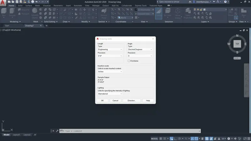
- select UN command < select engineering< precision 0'0"
- select line command< specify first point by cursor< drag the cursor to x-axis< give distance 2'
- select line command< select last point < drag the cursor z-axis
- select last point
- press c to close diagram
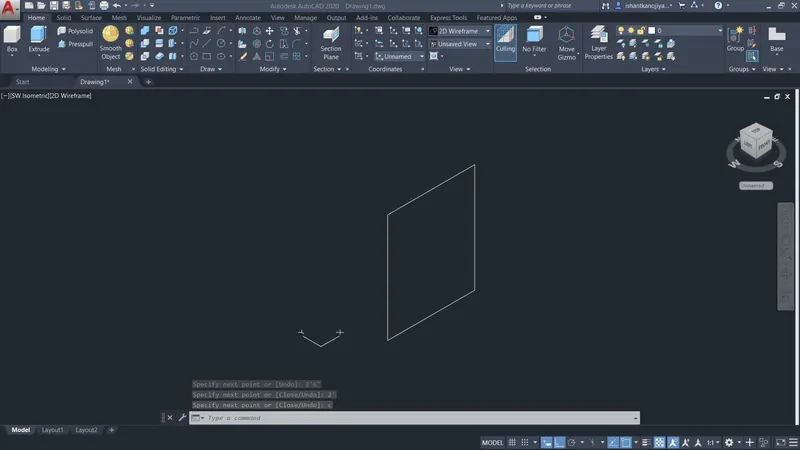
- select line command< select 3 point to first point of line
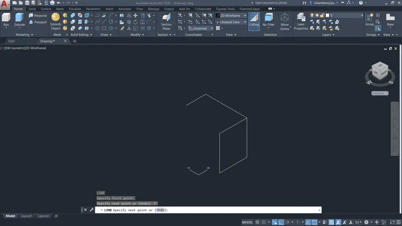
- again drag the cursor -ve x-axis
- again drag the cursor -ve y-axis< distance 3'< exit the line command
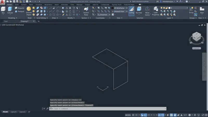
- select line command< select 6 point as first new line
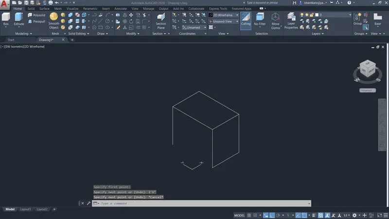
- select ucs command < re-specify x,y axis
- select offset command
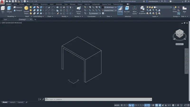
- sketch the rest lines
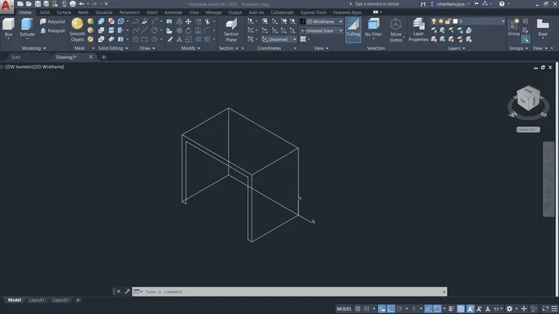
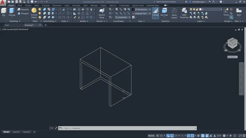
- select 3dface command
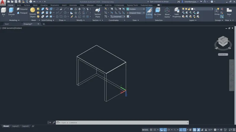
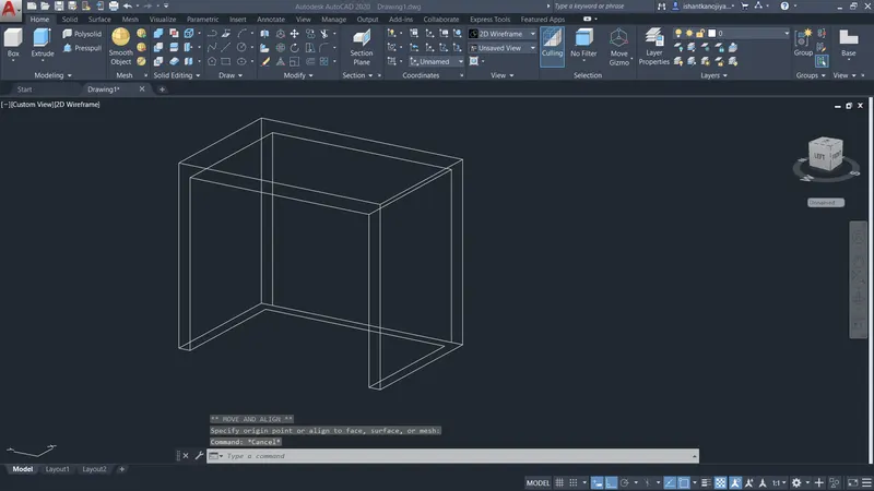

RESULT
2. Create a 3D Model of an Isolated Footing as shown in the Figure. Assume dimensions that are missing.
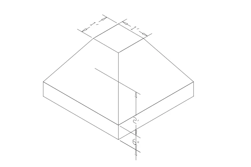
AIM- CREATE THE 3D MODEL OF an Isolated Footing SHOWN IN THE FIGURE.
INTRODUCTION-
AutoCAD-
- AutoCAD stands for Computer-Aided Design.
- AutoCAD is software developed by the company Autodesk.
- It allows you to draw and edit digital 2D and 3D designs more quickly and easily than you could by hand.
- This software is used for designing and drafting.
- It is used for a number of applications like creating blueprints for buildings, bridges, etc.
- AutoCAD is 2D and 3D computer aided drafting software application.
- AutoCAD software saves a huge time, saving time is equal to earn more income by more output, It is a simple enough software with the real user friendly interface, It is easy to grasp and it can provide you the basic exposure, It is very beneficial in designing 3D.
- Civil engineers design, construct, supervise, operate, and maintain large construction projects and systems, including roads, buildings, airports, tunnels, dams, bridges, and systems for water supply and sewage treatment.
AutoCAD 3D- Commands
- 3DMOVE: Click 3D Move in the Modify panel on the Home tab, or type 3DMOVE at the command line.
- 3DROTATE: Click 3D Rotate in the Modify panel on the Home tab, or type 3DROTATE at the command line.
- 3DSCALE: Click 3D Scale in the Modify panel, or type 3DSCALE at the command line.
- 3DALign: An improved version of the ALign command that includes additional options as well as the ability to move and rotate a copy of the selected objects and use Dynamic UCS with the command. Click 3D Align in the Modify panel on the Home tab.
- Fillet and chamfer: Because fillets and chamfers are common real-world features, it’s logical that tools for creating them are available. You can fillet or bevel the edges of a 3D solid by clicking the Fillet Edge (or Chamfer Edge) split button in the Solid Editing panel on the Solid tab.
- Shell (solidedit): Using this command you can convert a 3D solid into a hollow solid with a wall thickness. To use this command type SOLIDEDIT on the command line press enter type B press enter again type S and press enter again. Alternatively, you can also select the shell tool from Solid editing panel of the Solid tab.
- Surfpatch: Using this command you can fill the open areas of a surface like the top of a cylinder as shown in the animated image below.
- Moveface: Using this tool you can move faces like a groove of a 3D solid from one point to other as shown in the animated image below. For using this tool type SOLIDEDIT on the command line press enter then type F press enter then type M and press enter again.
- Surfoffset: Using this command you can offset any surface inside, outside or on both sides of the surface as shown in the animated image below.
- Extrude: This AutoCAD 3D Extrude command allows the user to create a 3D object by extruding a 2D face along a line or path. For example, A cylinder can be created by selecting a 2D circle and extruding it along with a path.
- Sweep: This command helps the user to extrude the 2D objects without the 2D face being orthogonal to the beginning of the path.
- Union: This AutoCAD 3D command allows the user to combine two objects converting them into one single object.
- Subtract: This command is opposite to the union command; this command works when there is a common area in both the objects. Then this command subtracts the object A from the object B.
- Intersect: With this AutoCAD 3D command, the user is left with the area that is common to both the objects.
- Slice: The SLice command lets you cut a 3D solid along a plane. You can slice a 3D solid by using a planar curve, such as a circle, 2D polyline, or surface, among many others. When you slice a 3D solid, you can choose which part of the 3D solid is retained, or you can keep both. This image shows a solid model that has been sliced in half.
- Thicken: Using this command you can convert a surface into a 3D solid by adding thickness to it.
- Polysolid: Using this command you can make a 3D wall-like shape as shown in the image here, you can also define height and thickness of this poly solid using command line options.
- XEDGES: You can extract edges of a 3D solid as 2D geometries using this tool. In the image shown here the XEDGES tool has been used to extract the edges of the 3D solid and then the solid geometry has been moved to reveal the edges only.
- Flatshot: This command is great for converting a 3D drawing into 2D and using this command you can also create multiple views of a single 3D drawing like the front, top and isometric on a single plane. To know more about this command follow the related article.
- Interfere: This command can be used to detect intersecting 3D solids. The command is especially useful in situations where you want to detect clashes between different solids like pipes and walls.
PROCEDURE:
- Select 3D modeling workspace
- select UN command < select engineering< precision 0'0"
- select top plane
- select rectangle command
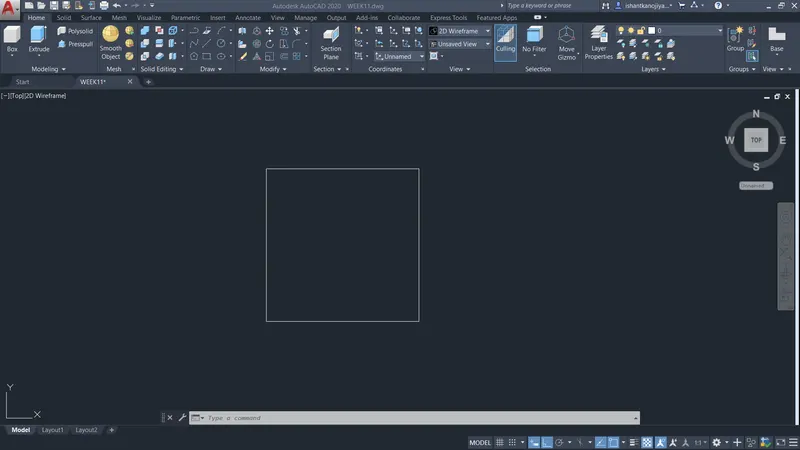
- select 3DFace command
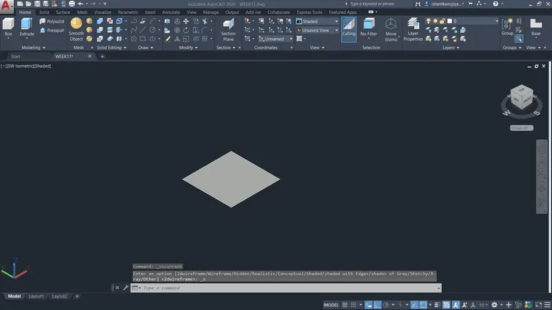
- select extruded command
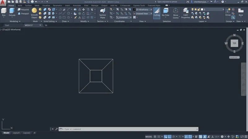
- select top plane
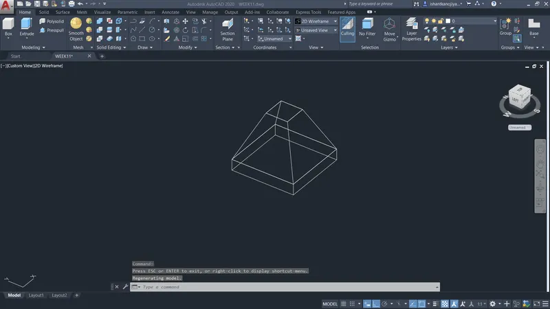
- select 3df command
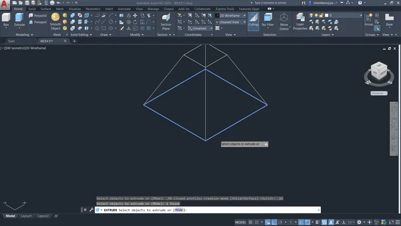
- select extrude command
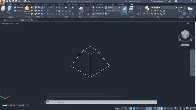
- hidden visual style
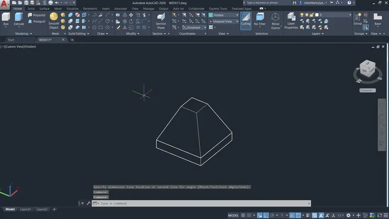
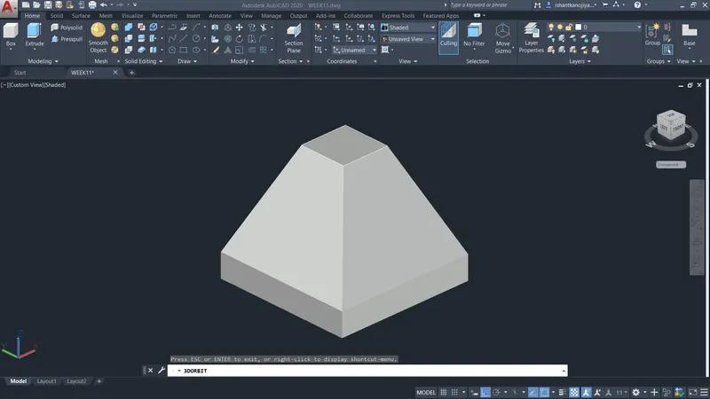
Result
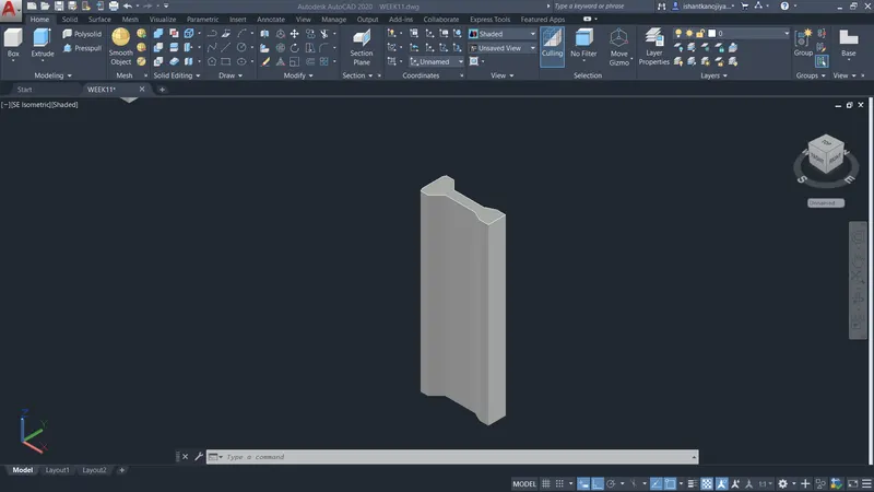
2. Create a 3D view of AASTHO Typer Girder as shown in the Figure. Assume dimensions that are missing.
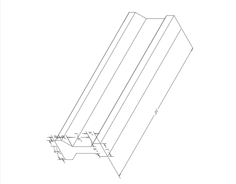
AIM- CREATE THE 3D VIEW OF THE AASTHO TYPE GIRDER SHOWN IN THE FIGURE.
INTRODUCTION-
AutoCAD-
- AutoCAD stands for Computer-Aided Design.
- AutoCAD is software developed by the company Autodesk.
- It allows you to draw and edit digital 2D and 3D designs more quickly and easily than you could by hand.
- This software is used for designing and drafting.
- It is used for a number of applications like creating blueprints for buildings, bridges, etc.
- AutoCAD is 2D and 3D computer aided drafting software application.
- AutoCAD software saves a huge time, saving time is equal to earn more income by more output, It is a simple enough software with the real user friendly interface, It is easy to grasp and it can provide you the basic exposure, It is very beneficial in designing 3D.
- Civil engineers design, construct, supervise, operate, and maintain large construction projects and systems, including roads, buildings, airports, tunnels, dams, bridges, and systems for water supply and sewage treatment.
AutoCAD 3D- Commands
- 3DMOVE: Click 3D Move in the Modify panel on the Home tab, or type 3DMOVE at the command line.
- 3DROTATE: Click 3D Rotate in the Modify panel on the Home tab, or type 3DROTATE at the command line.
- 3DSCALE: Click 3D Scale in the Modify panel, or type 3DSCALE at the command line.
- 3DALign: An improved version of the ALign command that includes additional options as well as the ability to move and rotate a copy of the selected objects and use Dynamic UCS with the command. Click 3D Align in the Modify panel on the Home tab.
- Fillet and chamfer: Because fillets and chamfers are common real-world features, it’s logical that tools for creating them are available. You can fillet or bevel the edges of a 3D solid by clicking the Fillet Edge (or Chamfer Edge) split button in the Solid Editing panel on the Solid tab.
- Shell (solidedit): Using this command you can convert a 3D solid into a hollow solid with a wall thickness. To use this command type SOLIDEDIT on the command line press enter type B press enter again type S and press enter again. Alternatively, you can also select the shell tool from Solid editing panel of the Solid tab.
- Surfpatch: Using this command you can fill the open areas of a surface like the top of a cylinder as shown in the animated image below.
- Moveface: Using this tool you can move faces like a groove of a 3D solid from one point to other as shown in the animated image below. For using this tool type SOLIDEDIT on the command line press enter then type F press enter then type M and press enter again.
- Surfoffset: Using this command you can offset any surface inside, outside or on both sides of the surface as shown in the animated image below.
- Extrude: This AutoCAD 3D Extrude command allows the user to create a 3D object by extruding a 2D face along a line or path. For example, A cylinder can be created by selecting a 2D circle and extruding it along with a path.
- Sweep: This command helps the user to extrude the 2D objects without the 2D face being orthogonal to the beginning of the path.
- Union: This AutoCAD 3D command allows the user to combine two objects converting them into one single object.
- Subtract: This command is opposite to the union command; this command works when there is a common area in both the objects. Then this command subtracts the object A from the object B.
- Intersect: With this AutoCAD 3D command, the user is left with the area that is common to both the objects.
- Slice: The SLice command lets you cut a 3D solid along a plane. You can slice a 3D solid by using a planar curve, such as a circle, 2D polyline, or surface, among many others. When you slice a 3D solid, you can choose which part of the 3D solid is retained, or you can keep both. This image shows a solid model that has been sliced in half.
- Thicken: Using this command you can convert a surface into a 3D solid by adding thickness to it.
- Polysolid: Using this command you can make a 3D wall-like shape as shown in the image here, you can also define height and thickness of this poly solid using command line options.
- XEDGES: You can extract edges of a 3D solid as 2D geometries using this tool. In the image shown here the XEDGES tool has been used to extract the edges of the 3D solid and then the solid geometry has been moved to reveal the edges only.
- Flatshot: This command is great for converting a 3D drawing into 2D and using this command you can also create multiple views of a single 3D drawing like the front, top and isometric on a single plane. To know more about this command follow the related article.
- Interfere: This command can be used to detect intersecting 3D solids. The command is especially useful in situations where you want to detect clashes between different solids like pipes and walls.
PROCEDURE:
- Select 3D modeling workspace
- select UN command < select engineering< precision 0'0"
- select top plane
- select line command
- drag cursorx-axis
- drag cursor -ve y-axis
- drag cursor y-axis< distance 6"
- drag drag cursor x-axis
- drag the cursor -ve y-axis< distance 1'
- mirror command use to mirror the lines
- sketch rest line
- select chamfer command
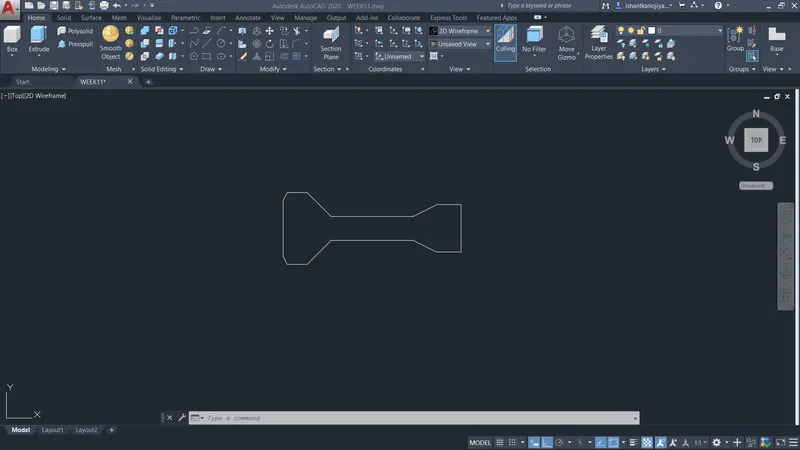
- select boundary command
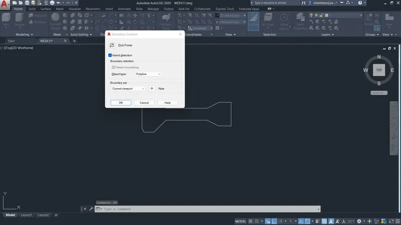
- select region option
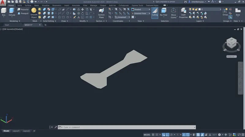
- select extruded command
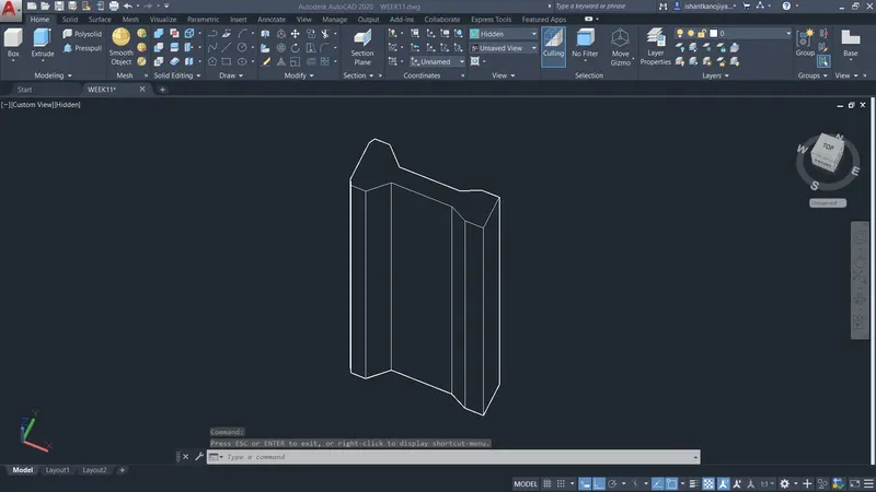
RESULT
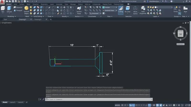
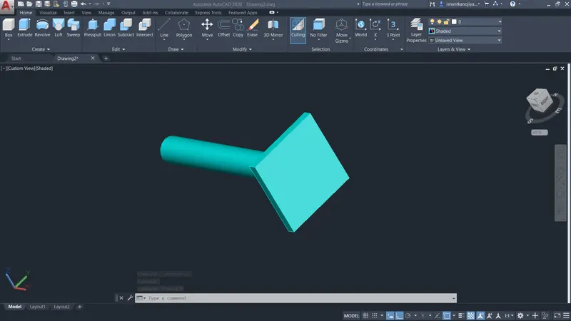
4. Create a 3D Model of a drop column with the panel as shown in section and isometric view. Assume dimensions that are missing.
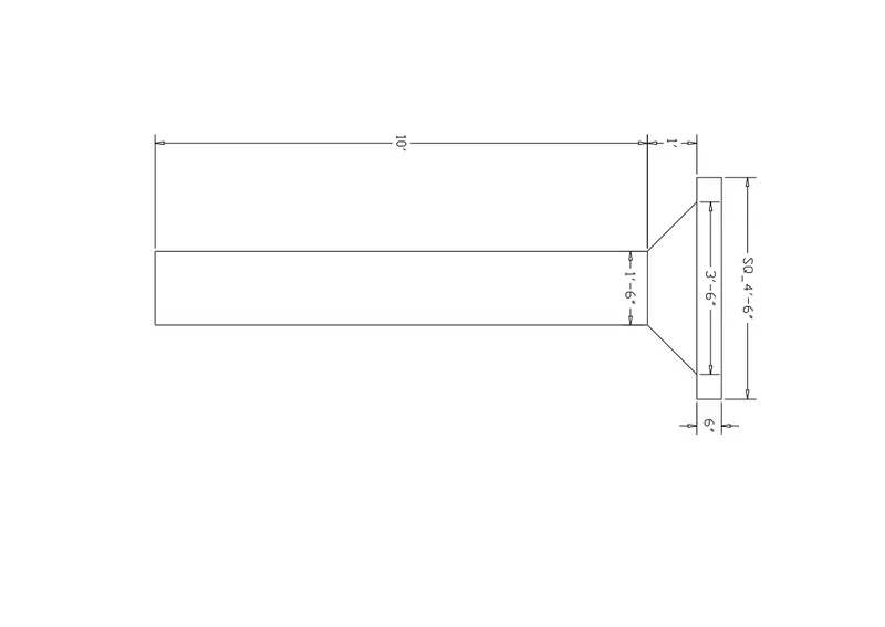
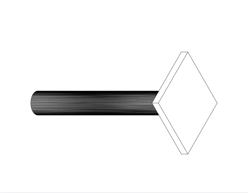
AIM- CREATE THE 3D MODEL OF A DROP COLUMN WITH A PANEL AS SHOWN IN THE FIGURE.
INTRODUCTION-
AutoCAD-
- AutoCAD stands for Computer-Aided Design.
- AutoCAD is software developed by the company Autodesk.
- It allows you to draw and edit digital 2D and 3D designs more quickly and easily than you could by hand.
- This software is used for designing and drafting.
- It is used for a number of applications like creating blueprints for buildings, bridges, etc.
- AutoCAD is 2D and 3D computer aided drafting software application.
- AutoCAD software saves a huge time, saving time is equal to earn more income by more output, It is a simple enough software with the real user friendly interface, It is easy to grasp and it can provide you the basic exposure, It is very beneficial in designing 3D.
- Civil engineers design, construct, supervise, operate, and maintain large construction projects and systems, including roads, buildings, airports, tunnels, dams, bridges, and systems for water supply and sewage treatment.
AutoCAD 3D- Commands
- 3DMOVE: Click 3D Move in the Modify panel on the Home tab, or type 3DMOVE at the command line.
- 3DROTATE: Click 3D Rotate in the Modify panel on the Home tab, or type 3DROTATE at the command line.
- 3DSCALE: Click 3D Scale in the Modify panel, or type 3DSCALE at the command line.
- 3DALign: An improved version of the ALign command that includes additional options as well as the ability to move and rotate a copy of the selected objects and use Dynamic UCS with the command. Click 3D Align in the Modify panel on the Home tab.
- Fillet and chamfer: Because fillets and chamfers are common real-world features, it’s logical that tools for creating them are available. You can fillet or bevel the edges of a 3D solid by clicking the Fillet Edge (or Chamfer Edge) split button in the Solid Editing panel on the Solid tab.
- Shell (solidedit): Using this command you can convert a 3D solid into a hollow solid with a wall thickness. To use this command type SOLIDEDIT on the command line press enter type B press enter again type S and press enter again. Alternatively, you can also select the shell tool from Solid editing panel of the Solid tab.
- Surfpatch: Using this command you can fill the open areas of a surface like the top of a cylinder as shown in the animated image below.
- Moveface: Using this tool you can move faces like a groove of a 3D solid from one point to other as shown in the animated image below. For using this tool type SOLIDEDIT on the command line press enter then type F press enter then type M and press enter again.
- Surfoffset: Using this command you can offset any surface inside, outside or on both sides of the surface as shown in the animated image below.
- Extrude: This AutoCAD 3D Extrude command allows the user to create a 3D object by extruding a 2D face along a line or path. For example, A cylinder can be created by selecting a 2D circle and extruding it along with a path.
- Sweep: This command helps the user to extrude the 2D objects without the 2D face being orthogonal to the beginning of the path.
- Union: This AutoCAD 3D command allows the user to combine two objects converting them into one single object.
- Subtract: This command is opposite to the union command; this command works when there is a common area in both the objects. Then this command subtracts the object A from the object B.
- Intersect: With this AutoCAD 3D command, the user is left with the area that is common to both the objects.
- Slice: The SLice command lets you cut a 3D solid along a plane. You can slice a 3D solid by using a planar curve, such as a circle, 2D polyline, or surface, among many others. When you slice a 3D solid, you can choose which part of the 3D solid is retained, or you can keep both. This image shows a solid model that has been sliced in half.
- Thicken: Using this command you can convert a surface into a 3D solid by adding thickness to it.
- Polysolid: Using this command you can make a 3D wall-like shape as shown in the image here, you can also define height and thickness of this poly solid using command line options.
- XEDGES: You can extract edges of a 3D solid as 2D geometries using this tool. In the image shown here the XEDGES tool has been used to extract the edges of the 3D solid and then the solid geometry has been moved to reveal the edges only.
- Flatshot: This command is great for converting a 3D drawing into 2D and using this command you can also create multiple views of a single 3D drawing like the front, top and isometric on a single plane. To know more about this command follow the related article.
- Interfere: This command can be used to detect intersecting 3D solids. The command is especially useful in situations where you want to detect clashes between different solids like pipes and walls.
Procedure:
- select drafting and annotation workspace
- select UN command < select engineering< precision 0'0"
- select rectangle command<specify point<select dimension <give dim 6"*4'6"<specify side <press enter
- select 3D modeling workspace
- select 3DR command< select object <select rotation axis<press enter
- select 3DF command<select rectangle as object <specify edges first,second,third,fourth edge<press enter
- select extrude command<select rectangle as object <extrude distance 4'6" <press enter
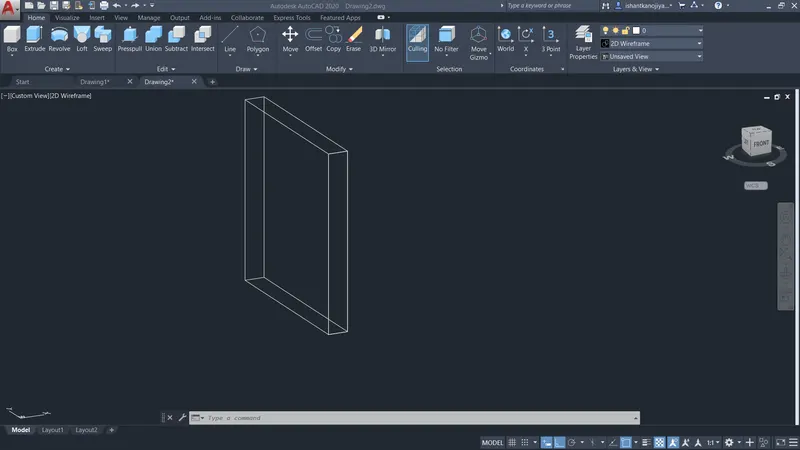
- select ucs icon <select face <select back side
- select circle command< bigger circle specify center of the circle to center of rectangle <select diameter 3'6"
- select circle command< smaller circle specify center of circle<select diameter 1'6"<exit command
- select boundary command<select region option<select circles as object <press enter
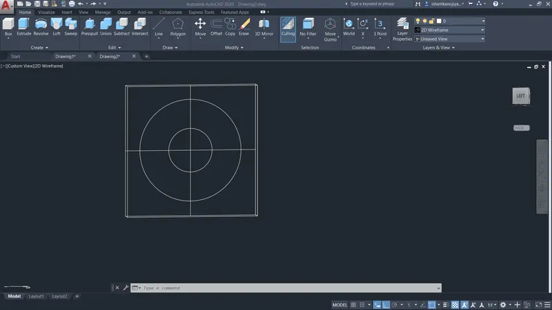
- select extrude command< select bigger circle as object< select taper angle <angle 45 degree <distance 1'<press enter
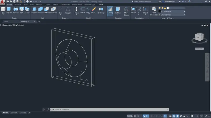
- select extrude command< select smaller circle as object <distance 11' <press enter
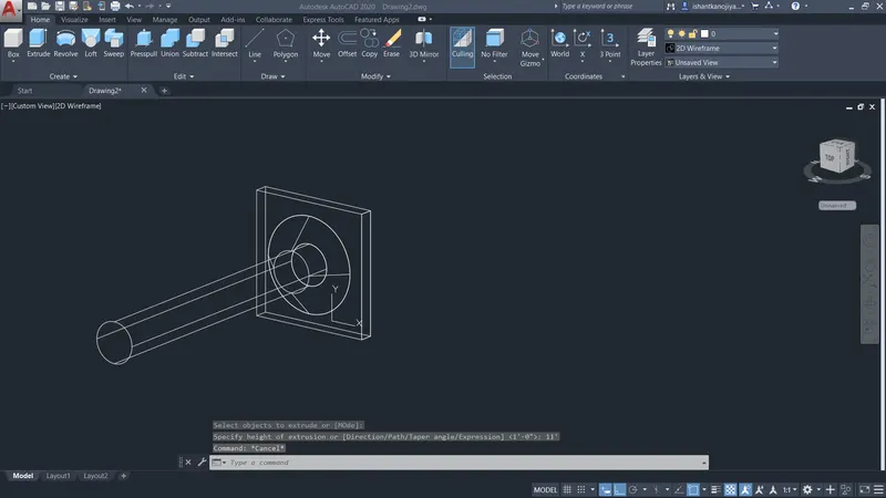
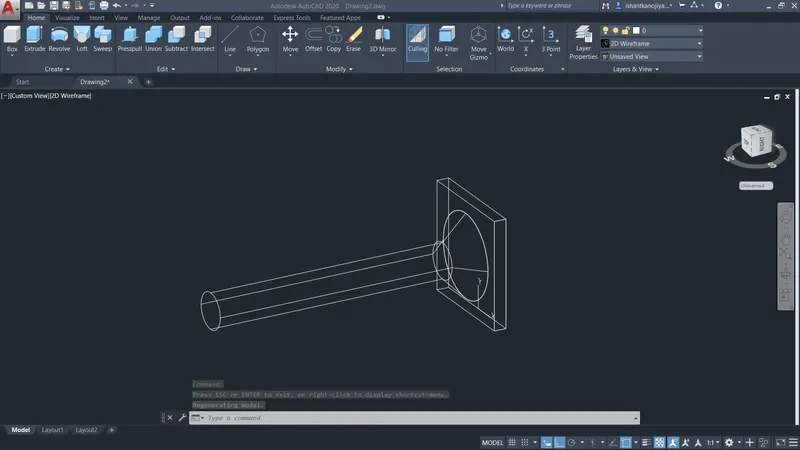
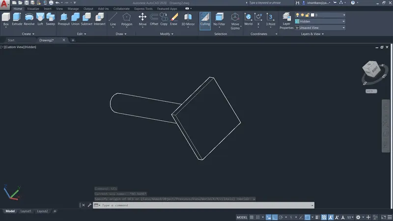
- select union command<select all diagram as object <press enter
RESULT
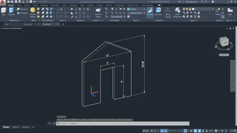
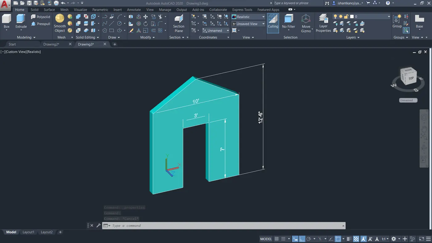
1. Create a 3D Model of a wall as shown in the section. Assume dimensions that are missing.
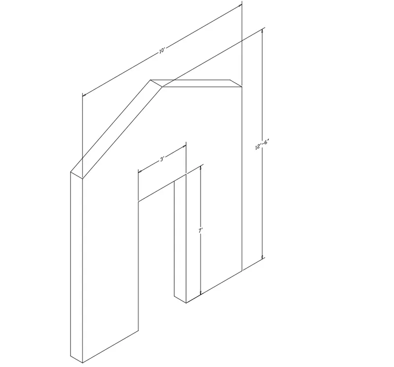
AIM- CREATE THE 3D MODEL OF A WALL AS SHOWN IN THE FIGURE. CONSIDER WALL THICKNESS AS 9".
INTRODUCTION-
AutoCAD-
- AutoCAD stands for Computer-Aided Design.
- AutoCAD is software developed by the company Autodesk.
- It allows you to draw and edit digital 2D and 3D designs more quickly and easily than you could by hand.
- This software is used for designing and drafting.
- It is used for a number of applications like creating blueprints for buildings, bridges, etc.
- AutoCAD is 2D and 3D computer aided drafting software application.
- AutoCAD software saves a huge time, saving time is equal to earn more income by more output, It is a simple enough software with the real user friendly interface, It is easy to grasp and it can provide you the basic exposure, It is very beneficial in designing 3D.
- Civil engineers design, construct, supervise, operate, and maintain large construction projects and systems, including roads, buildings, airports, tunnels, dams, bridges, and systems for water supply and sewage treatment.
AutoCAD 3D- Commands
- 3DMOVE: Click 3D Move in the Modify panel on the Home tab, or type 3DMOVE at the command line.
- 3DROTATE: Click 3D Rotate in the Modify panel on the Home tab, or type 3DROTATE at the command line.
- 3DSCALE: Click 3D Scale in the Modify panel, or type 3DSCALE at the command line.
- 3DALign: An improved version of the ALign command that includes additional options as well as the ability to move and rotate a copy of the selected objects and use Dynamic UCS with the command. Click 3D Align in the Modify panel on the Home tab.
- Fillet and chamfer: Because fillets and chamfers are common real-world features, it’s logical that tools for creating them are available. You can fillet or bevel the edges of a 3D solid by clicking the Fillet Edge (or Chamfer Edge) split button in the Solid Editing panel on the Solid tab.
- Shell (solidedit): Using this command you can convert a 3D solid into a hollow solid with a wall thickness. To use this command type SOLIDEDIT on the command line press enter type B press enter again type S and press enter again. Alternatively, you can also select the shell tool from Solid editing panel of the Solid tab.
- Surfpatch: Using this command you can fill the open areas of a surface like the top of a cylinder as shown in the animated image below.
- Moveface: Using this tool you can move faces like a groove of a 3D solid from one point to other as shown in the animated image below. For using this tool type SOLIDEDIT on the command line press enter then type F press enter then type M and press enter again.
- Surfoffset: Using this command you can offset any surface inside, outside or on both sides of the surface as shown in the animated image below.
- Extrude: This AutoCAD 3D Extrude command allows the user to create a 3D object by extruding a 2D face along a line or path. For example, A cylinder can be created by selecting a 2D circle and extruding it along with a path.
- Sweep: This command helps the user to extrude the 2D objects without the 2D face being orthogonal to the beginning of the path.
- Union: This AutoCAD 3D command allows the user to combine two objects converting them into one single object.
- Subtract: This command is opposite to the union command; this command works when there is a common area in both the objects. Then this command subtracts the object A from the object B.
- Intersect: With this AutoCAD 3D command, the user is left with the area that is common to both the objects.
- Slice: The SLice command lets you cut a 3D solid along a plane. You can slice a 3D solid by using a planar curve, such as a circle, 2D polyline, or surface, among many others. When you slice a 3D solid, you can choose which part of the 3D solid is retained, or you can keep both. This image shows a solid model that has been sliced in half.
- Thicken: Using this command you can convert a surface into a 3D solid by adding thickness to it.
- Polysolid: Using this command you can make a 3D wall-like shape as shown in the image here, you can also define height and thickness of this poly solid using command line options.
- XEDGES: You can extract edges of a 3D solid as 2D geometries using this tool. In the image shown here the XEDGES tool has been used to extract the edges of the 3D solid and then the solid geometry has been moved to reveal the edges only.
- Flatshot: This command is great for converting a 3D drawing into 2D and using this command you can also create multiple views of a single 3D drawing like the front, top and isometric on a single plane. To know more about this command follow the related article.
- Interfere: This command can be used to detect intersecting 3D solids. The command is especially useful in situations where you want to detect clashes between different solids like pipes and walls.
PROCEDURE:
- select drafting and annotation workspace
- select UN command < select engineering< precision 0'0"
- select line command<specify first point <drag cursor x-axis<distance 10'
- again line command<select midpoint of first-line as the first point<drag cursor -ve y-axis< distance 12'6"
- select first line <move command < drag the -ve y-axis at the distance 3'
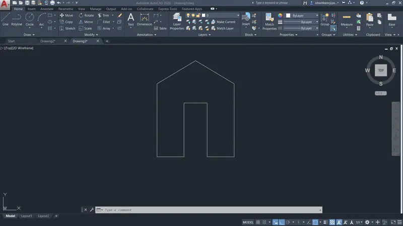
- select line command<select first point <and join the third point directly
- again select second point < join the third point directly
- trim the rest of unwanted lines
- select offset command< select the second line as object <distance 5' <both side offset <exit the offset command
- select offset command<select the second line as object <distance 1'6" <both side offset (for opening)<exit command
- select line command<join the bottom point each other
- select unwanted lines
- select 3D modeling workspace
- select 3df command<select closed object <press enter(surface is generated)
- select 3dr command<rotated the required axis
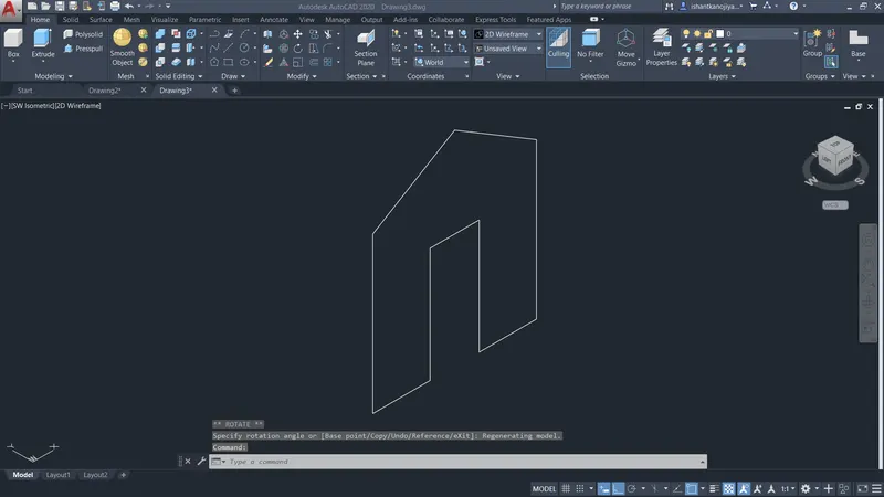
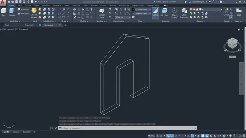
- select extrude command<select wall as object <distance 9"<drag the direction <press enter
hidden visual style
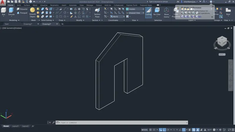
RESULT