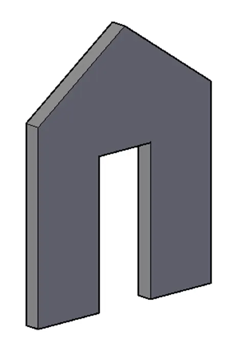
Creating various 3D Models like Furniture, Footing, Girder, Column drop with panel and Gable Wall in AutoCad
3D FURNITURE
Aim: To create a 3D Furniture element as shown in the Figure in AutoCAD 3D modelling
Introduction: The 3D Furniture element is created in AutoCAD using 3D modelling tool. The procedure of drawing is explained and the final results are given.
Commands Used:
Units
Extrude
Shell
UCS
Box
Move
3d orbit
Dimension
Procedure:
Open the AutoCAD, switch to 3D modelling by clicking on workspace switching and click on the home button near the view cube.
Type unit or UN in the command line and press enter
Set type of unit as engineering and precision as 0’ 0”
In insertion scale set unit as Inch.
Set upper limit and lower limit of the drawing
Set the limits and zoom - all.
Create a box by clicking from the toolbar or box command, give the length as 3' and width as 2'6".
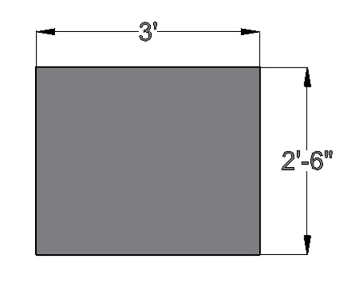
Height is to be specified, give the height as 2'6".

Type Solidedit in command line and select Body, then select shell
Select the created box and remove the front and bottom face
Then enter the shell offset distance as 2”
Use dimension tool and align the face to get proper dimensions
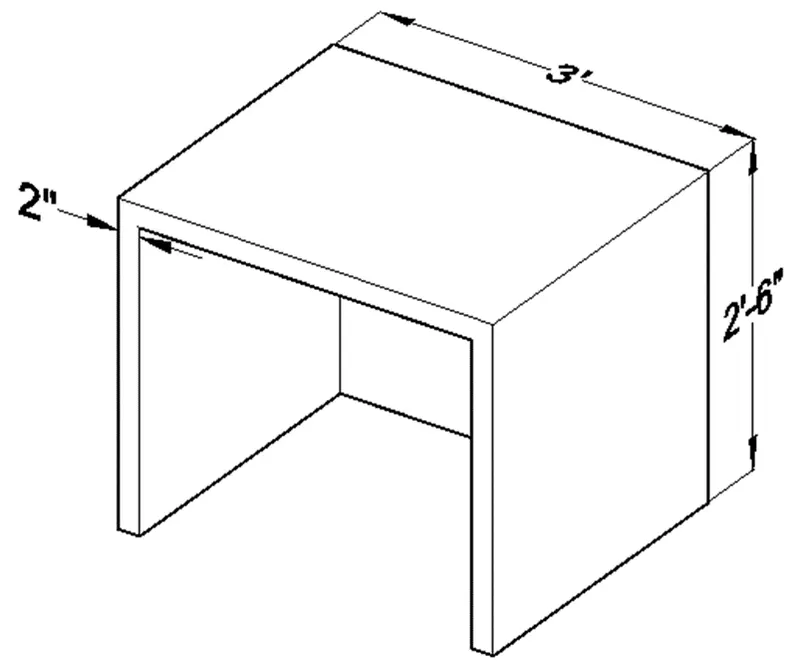
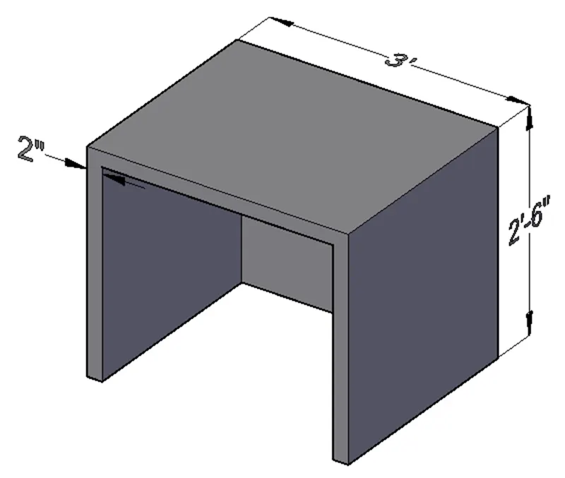
RESULT
The 3D Furniture element as shown in the Figure is created using AutoCAD 3D modelling
3D MODEL OF AN ISOLATED FOOTING
Aim: To create 3D Model of an Isolated footing as shown in the Figure in AutoCAD 3D modelling
Introduction: The 3D Model of an Isolated footing is created in AutoCAD using 3D modelling tool. The procedure of drawing is explained and the final results are given.
Commands Used:
Units
Rectangle
Offset
Extrude
Loft
UCS
Move
3d orbit
Dimension
Procedure:
Open the AutoCAD, switch to 3D modelling by clicking on workspace switching and click on the home button near the view cube.
Type unit or UN in the command line and press enter
Set type of unit as engineering and precision as 0’ 0”
In insertion scale set unit as Inch.
Set upper limit and lower limit of the drawing
Set the limits and zoom - all.
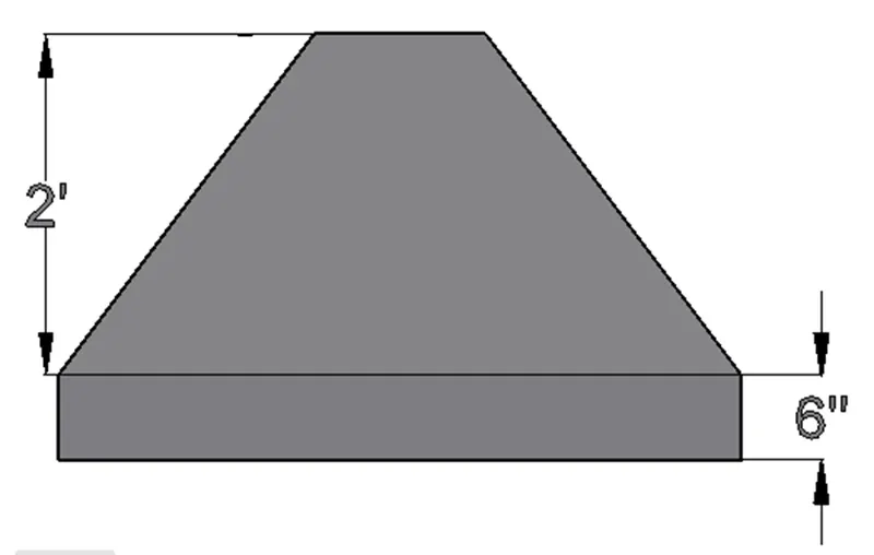
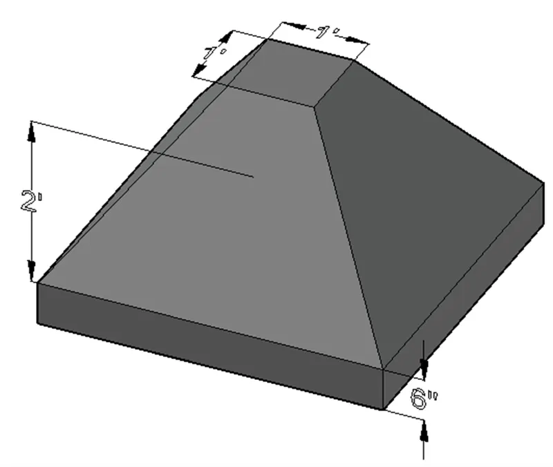
Draw rectangle of length 4 and width 4’
Offset rectangle inwards with offset distance of 1.5’
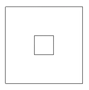
Then move the offset rectangle in z detection to a distance of 2”
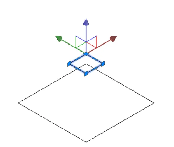
Select both the shapes and click on loft tool
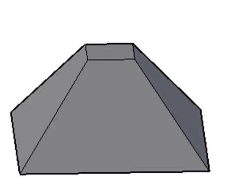
Select bottom face of the model and extrude to a distance of 6”
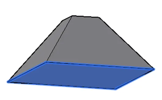
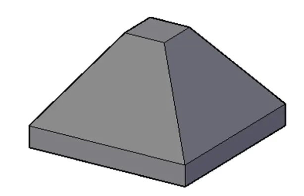
Use dimension tool and align the face to get proper dimensions
RESULT
The 3D Model of an Isolated footing as shown in the Figure is created using AutoCAD 3D modelling
3D VIEW OF THE AASTHO TYPE GIRDER
Aim: To create 3D view of the AASTHO Type Girder as shown in the Figure in AutoCAD 3D modelling
Introduction: The 3D view of the AASTHO Type Girder is created in AutoCAD using 3D modelling tool. The procedure of drawing is explained and the final results are given.
Commands Used:
Units
Poly line
Extrude
UCS
Move
3d orbit
Dimension
Procedure:
Open the AutoCAD, switch to 3D modelling by clicking on workspace switching and click on the home button near the view cube.
Type unit or UN in the command line and press enter
Set type of unit as engineering and precision as 0’ 0”
In insertion scale set unit as Inch.
Set upper limit and lower limit of the drawing
Set the limits and zoom - all.
Type PL to invoke poly line tool and draw the shape of the girder according to the given dimension
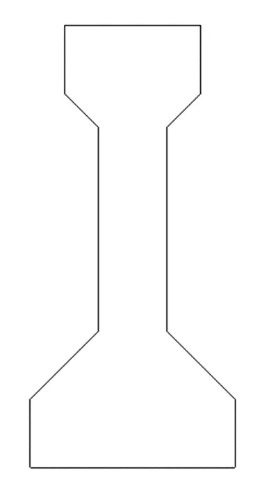
Chamfer the bottom edge on both side with each side dimension of 1”
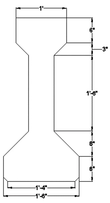
Select the profile and extrude to 10” length and use 3D-orbit to rotate for suitable view
Use dimension tool and align the face to get proper dimensions
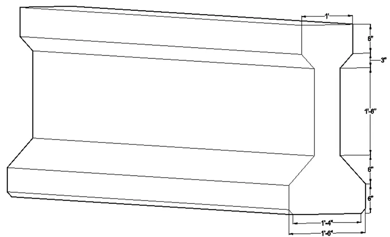
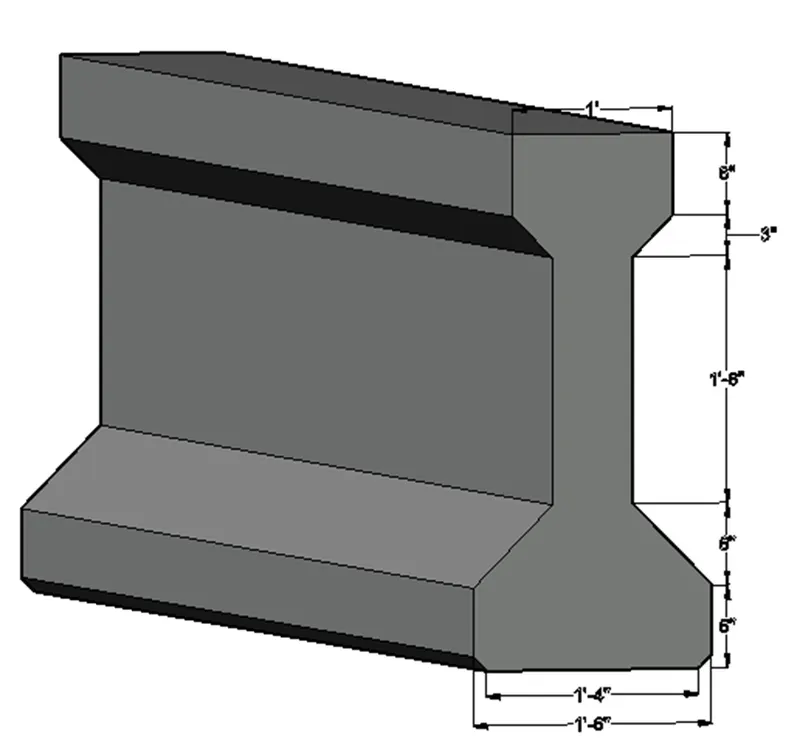
RESULT
The 3D view of the AASTHO Type Girder as shown in the Figure is created using AutoCAD 3D modelling
3D MODEL OF A DROP COLUMN WITH PANEL
Aim: To create 3d Model of a drop column with panel as shown in the Figure in AutoCAD 3D modelling
Introduction: The 3d Model of a drop column with panel is created in AutoCAD using 3D modelling tool. The procedure of drawing is explained and the final results are given.
Commands Used:
Units
Rectangle
Extrude
Circle
Offset
Copy
Loft
UCS
Move
3d orbit
Dimension
Procedure:
Open the AutoCAD, switch to 3D modelling by clicking on workspace switching and click on the home button near the view cube.
Type unit or UN in the command line and press enter
Set type of unit as engineering and precision as 0’ 0”
In insertion scale set unit as Inch.
Set upper limit and lower limit of the drawing
Set the limits and zoom - all.
Create a rectangle of length and width of 4.6’
Extrude the rectangle to a distance of 6”
Turn on the Dynamic UCS and select the upper face of the solid
Create a circle of diameter 3’ 6” from the face center
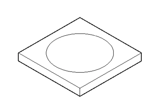
Offset the circle inwards with offset distance of 1’
Move the offset circle in Z direction to a distance of 1’
And create a copy then move to 10’ in Z direction
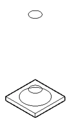
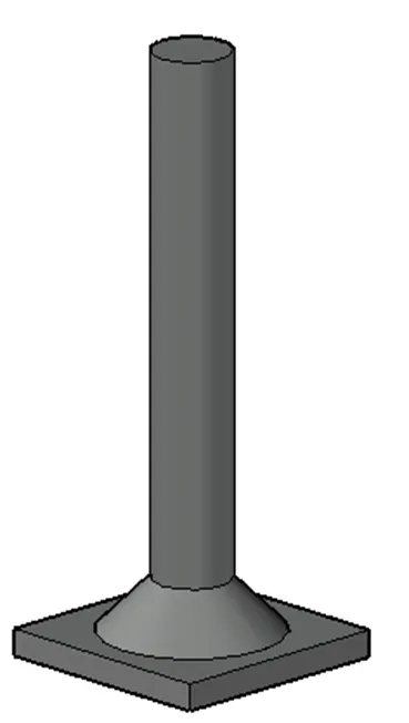
Select the 3 circles and Create Loft
Use dimension tool and align the face to get proper dimensions
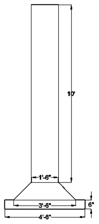
RESULT
The 3d Model of a drop column with panel as shown in the Figure is created using AutoCAD 3D modelling
3D MODEL OF A WALL
Aim: To create 3d model of a wall as shown in the Figure in AutoCAD 3D modelling
Introduction: The 3d model of a wall is created in AutoCAD using 3D modelling tool. The procedure of drawing is explained and the final results are given.
Commands Used:
Units
Rectangle
Extrude
Polyline
UCS
3d orbit
Dimension
Procedure:
Open the AutoCAD, switch to 3D modelling by clicking on workspace switching and click on the home button near the view cube.
Type unit or UN in the command line and press enter
Set type of unit as engineering and precision as 0’ 0”
In insertion scale set unit as Inch.
Set upper limit and lower limit of the drawing
Set the limits and zoom - all.
Create a rectangle of length 10’ and width 12’ 6”
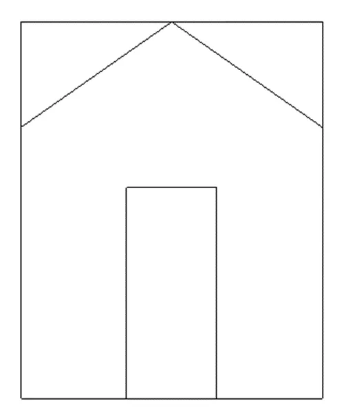
Draw door of 3’ wide and 7’ Hight as shown in figure
Draw the slopes from the mid of wall to edge and connect at 9’ height
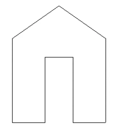
Trim the extra lines
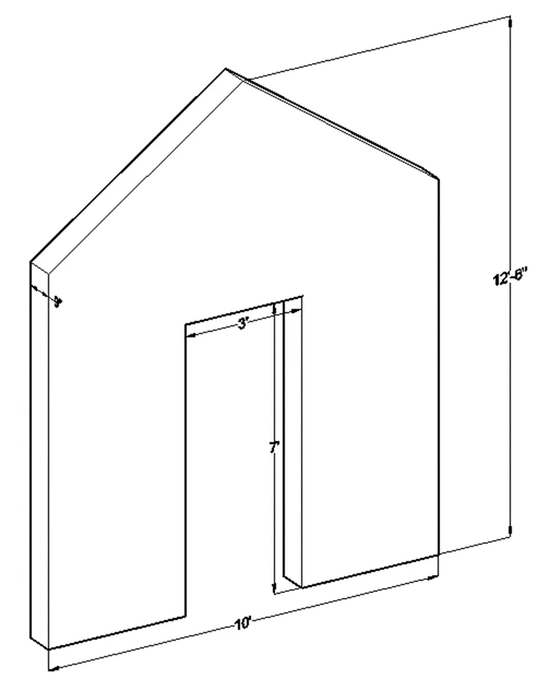
Extrude the wall with thickness of 9”
Use dimension tool and align the face to get proper dimensions
RESULT
The 3d model of a wall as shown in the Figure is created using AutoCAD 3D modelling