Creating various 3D Models like Furniture, Footing, Girder, Column drop with panel and Gable Wall in AutoCad
1,
AIM: To Create a 3D Furniture element as Shown in Figure.
INTRODUCTION:
- In order to design 3D model, we have to change the working spacing as 3d modelling or 3d basics.
- In 3D modelling, we have to work in 3-dimensional such as x-axis, y-axis and z-axis.
- We can work by changing the visual styles such as Top View,Front View, Bottom, Left, Right and Isometric Views.
PROCEDURE:
- Set the units of the drawing sheet such as Engineering type.
- Then set the limits of the sheet and start drafting the models.
- Using Box cammnd from command prompt, specify the centre or edge>> enter.
- Then specify the cube or length>> length.
- Specify the length>>3feets., width>> 2feets.
- Specify the heigth as>>2feets and 6 inches.
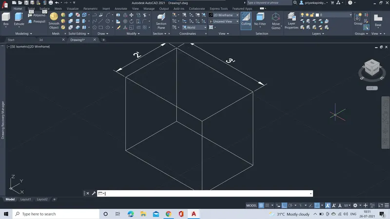
- Then by changing the visual style as isometric, insert the another box or rectangle.
- Then using subtract command, subtract the object from the slected object.
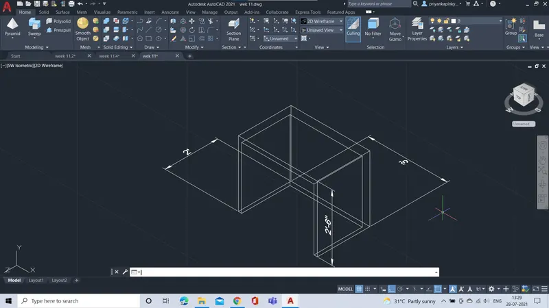
- Then, finally 3D furniture is created.
RESULT:
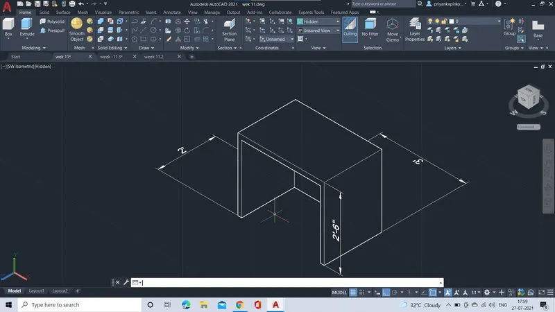
THEREFORE, 3D VIEW OF FURNITURE IS CREATED.
2,
AIM: To Create a 3d model of an isolated footing.
INTRODUCTION:
- In order to design 3D model, we have to change the working spacing as 3d modelling or 3d basics.
- In 3D modelling, we have to work in 3-dimensional such as x-axis, y-axis and z-axis.
- We can work by changing the visual styles such as Top View,Front View, Bottom, Left, Right and Isometric Views.
PROCEDURE:
- Set the units of the drawing sheet such as Engineering type.
- Then set the limits of the sheet and start drafting the model.
- By changing the visual style to Top view.
- Using the command rectangle , specify dimensions such as length 2feets, width 2 feets.
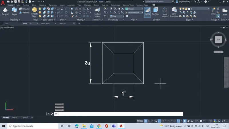
- using the rectangle command, specify length 1 feet ad width 1 feet and specify in z -axis.
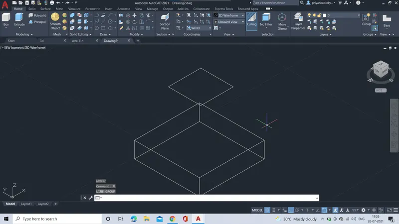
- Using line commad join the edges of the footing.
- Then, 3D model of isolated footing is created.
RESULT:
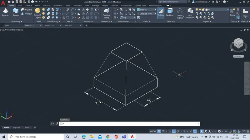
THEREFORE 3D VIEW OF ISOLATED FOOTING IS CREATED.
3,
AIM: To Create 3D view of the AASTHO type of Grider.
INTRODUCTION:
- In order to design 3D model, we have to change the working spacing as 3d modelling or 3d basics.
- In 3D modelling, we have to work in 3-dimensional such as x-axis, y-axis and z-axis.
- We can work by changing the visual styles such as Top View,Front View, Bottom, Left, Right and Isometric Views.
PROCEDURE:
- Set the units of the drawing sheet such as Engineering type.
- Then set the limits of the sheet and start drafting the model.
- In top view, using line command, draft the I - SECTION of given dimensions from the figure.
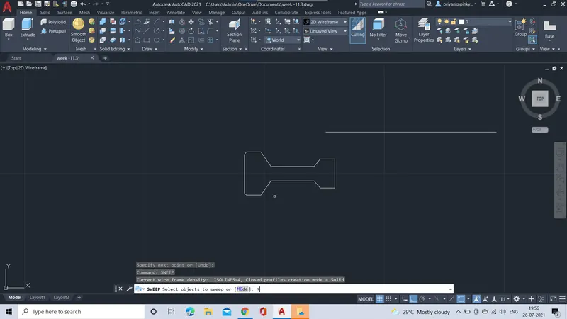
- Then Draw a straight line using line command.
- Then using sweep tool from command prompt, select the object to sweep.
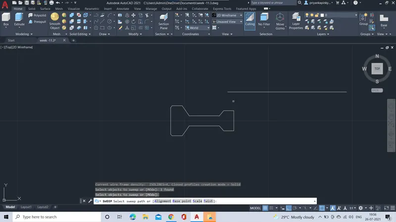
- Then select the sweep path or Alignment, Base point, Scale, Twist:
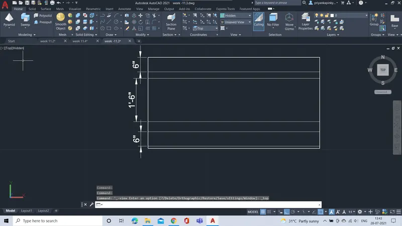
- Then select the path as straight line.
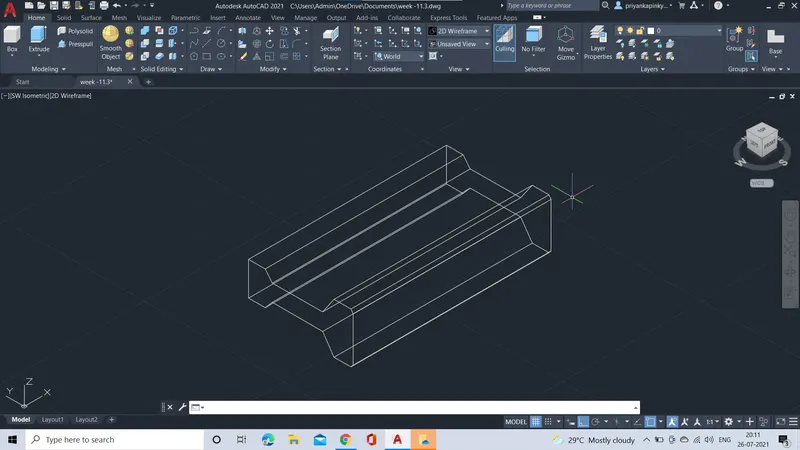
- Then the 3d view of the AASTHO type Grider can be seen by changing the visual type into Isometric view.
RESULT:

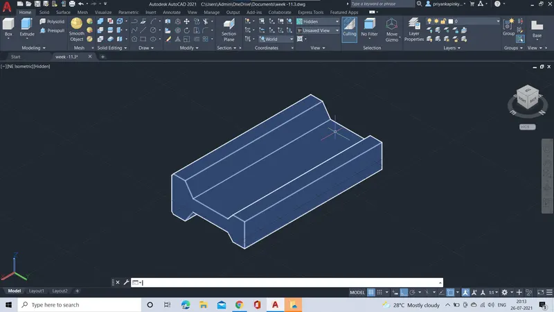
3D VIEW OF AASTHO TYPE GRIDER IS CREATED.
4,
AIM: To create the 3D model of the drop column with the pannel as shown in figure
INTRODUCTION:
- In order to design 3D model, we have to change the working spacing as 3d modelling or 3d basics.
- In 3D modelling, we have to work in 3-dimensional such as x-axis, y-axis and z-axis.
- We can work by changing the visual styles such as Top View,Front View, Bottom, Left, Right and Isometric Views.
PROCEDURE:
- Set the units of the drawing sheet such as Engineering type.
- Then set the limits of the sheet and start drafting the model.
- In top view, Daw the section of the column.
- Using the rectangle command, specify the length, width as 4'-6" respeitively and specify heigth as 6".
- using rectangle command , specify the length, width as 3'-6"respectively in z-aixs of heigth 6''excatly above the pannel.
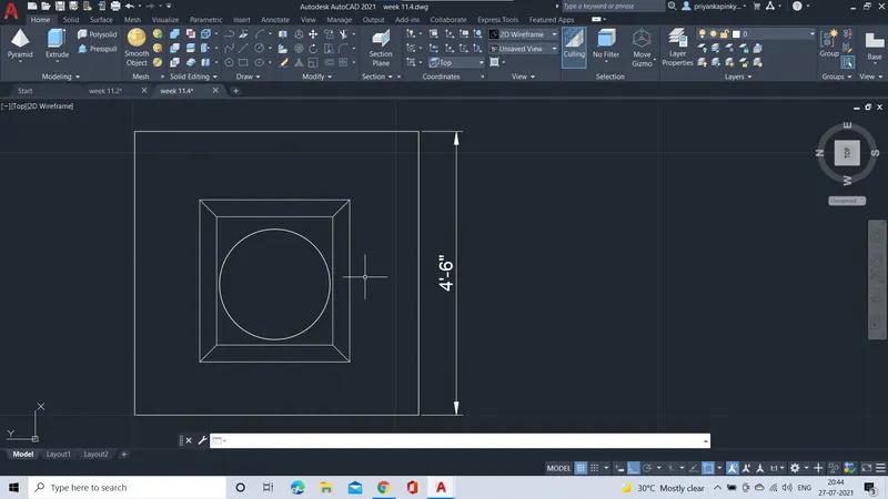
- using extrude command above the rectangle of heigth 1'-0 with taper angle of 15.
- Using pressfull tools , select the surface of the object and specify the heigth of the column as 10'-0".
- Then the drop column with pannel is created.
RESULT:
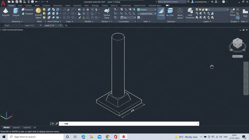
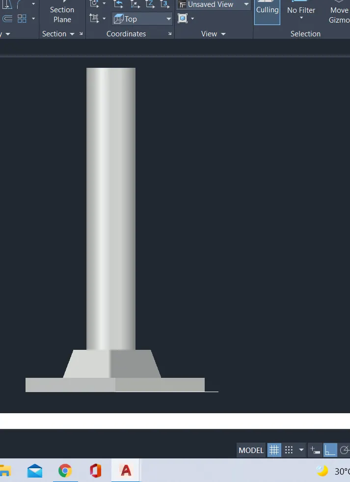
THERE DROP COLUMN WITH PANNEL IS CRETAED.
5,
AIM: To created the 3D model of the wall as shown in figure.
INTRODUCTION:
- In order to design 3D model, we have to change the working spacing as 3d modelling or 3d basics.
- In 3D modelling, we have to work in 3-dimensional such as x-axis, y-axis and z-axis.
- We can work by changing the visual styles such as Top View,Front View, Bottom, Left, Right and Isometric Views.
PROCEDURE:
- Set the units of the drawing sheet such as Engineering type.
- Then set the limits of the sheet and start drafting the model.
- Using line command , draw the rectangle of 10'-0 in length and 0'-9" in width.
- Create a region and make the surface and extrude to a heigth of 10'-0" .
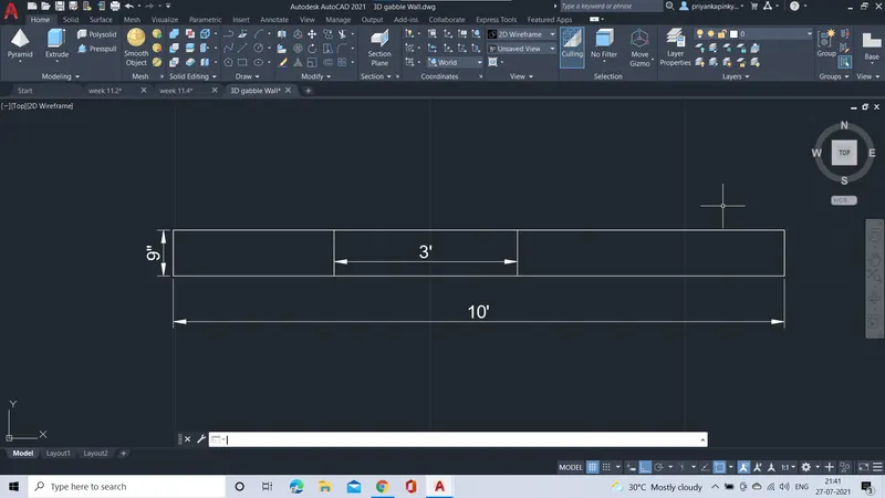
- From isometric view insert a rectangle d 3'-0 n length and with of 0'-9"and heigth of 7'-0".
- Using the Subtract command , subtract the selected object from the object and i forms the opening as door in the wall.
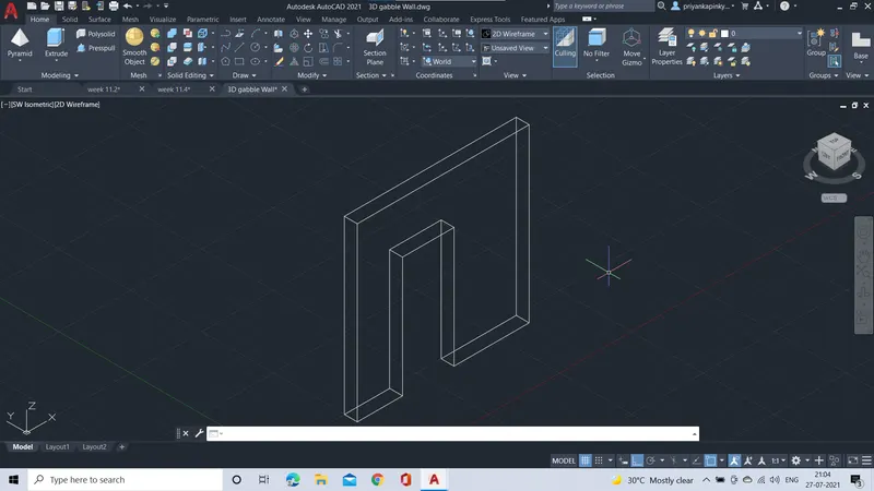
RESULT:
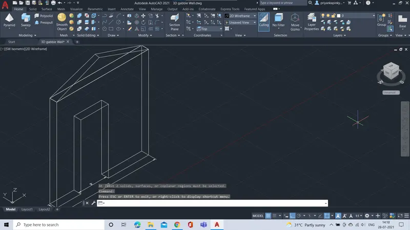
ISOMETRIC WALL IS CRAETED.