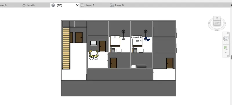
Creating Levels, Grids, Layout and model elements for a residential unit using REVIT
1) What is BIM? Summarize the features of BIM and benefits of using BIM over 2D CAD tools.BIM is a process for creating and managing information on a construction project throughout its whole life cycle.
Ans: BIM stands for Building Information Modeling. It is process, a coordinated digital description of every aspect of the built asset is developed, using a set of appropriate technology.It is likely that this digital description includes a combination of information-rich 3D models and associated structured data such as product, execution and handover information.BIM dimensions have evolved from a need to differentiate between modelling geometry in two dimensions or three dimensions.
This has been part of the modelling evolution, moving from drawing boards to the first 2D CAD systems, to 3D modelling packages,modelling scheduling information to model construction sequences and adding financial cost.
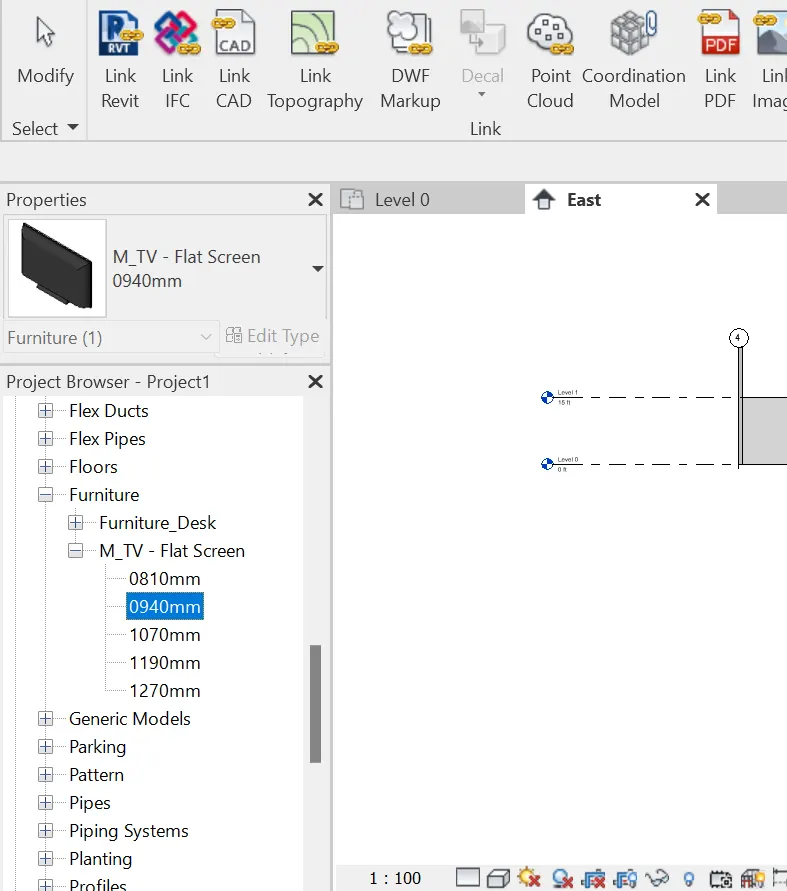
2) Understand the concept of Categories, Families, Elements, Instances in Revit. Go to Insert Tab, choose a category. Pick a family and element. Understand the instances and insert it to Revit model.
Ans:
- Group of elements contains common property is known as family
- Different property of element is known as category
- Element is used to identify the model for example :wall,floor e.t.c
- open revit
- goto insert tab
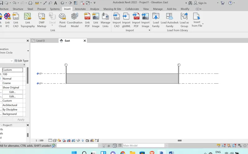
select load family
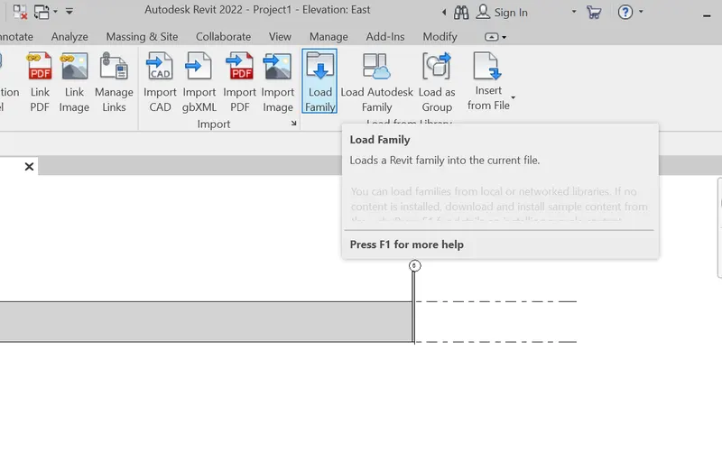
- go through pupup tab select family file to insert.
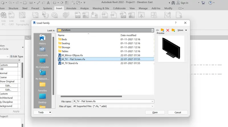
Result :
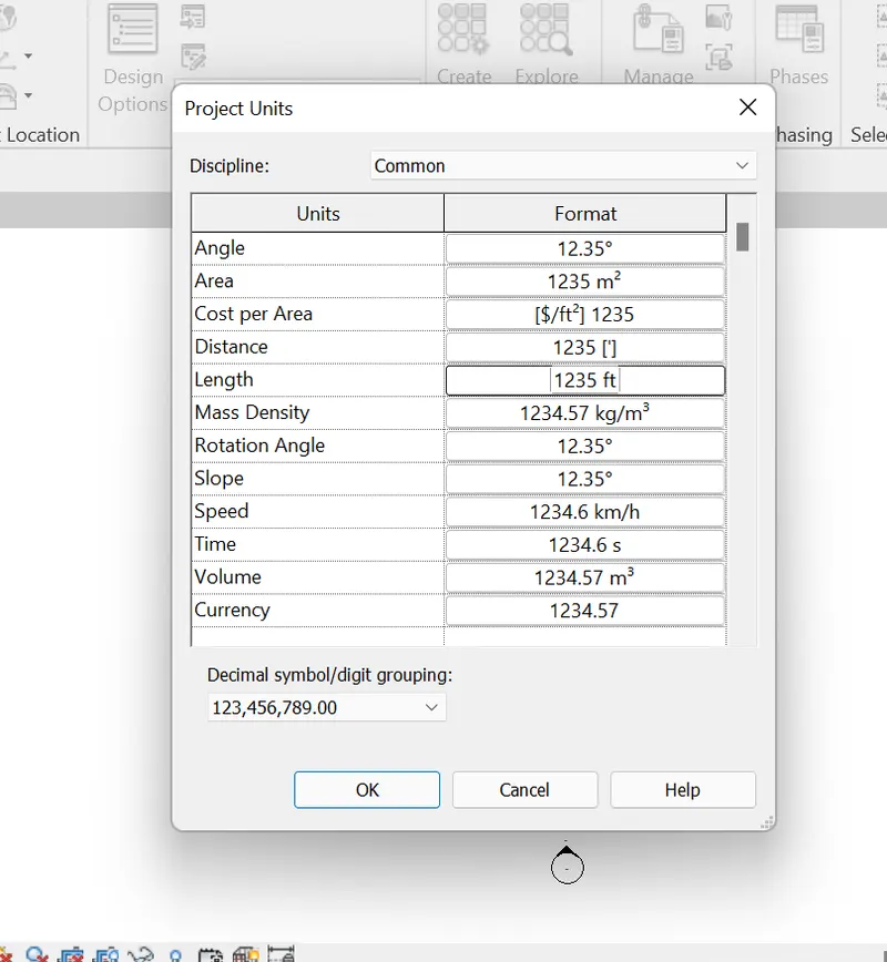
3) Setting up a Project – Open a project file with architectural template. Save the file with appropriate name. Set up the project units to Imperial / Metric based on your convenience of modelling. Complete the project information under Manage tab. Set up the maximum backups for project file to 3
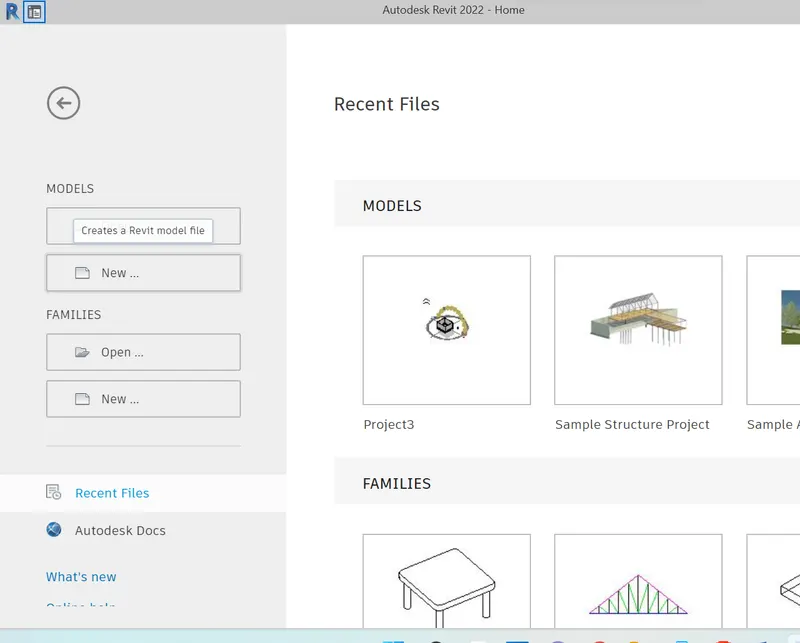
- Open revit
- select New option
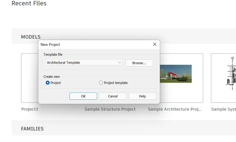
- select Architectural template
- Goto manage tab
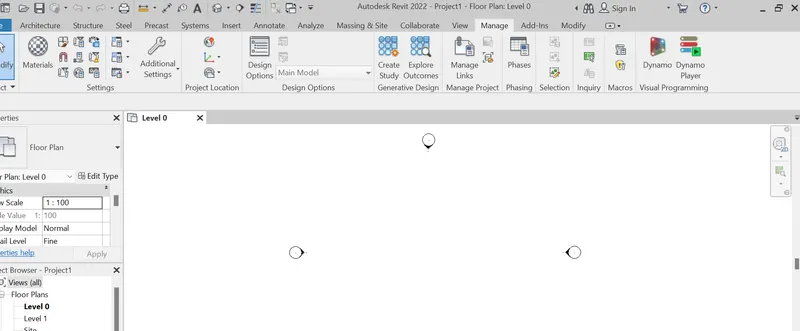
- select project units
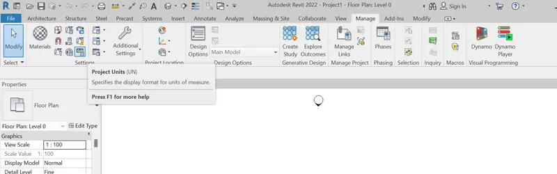
- change the unit in to feets
- select project Information
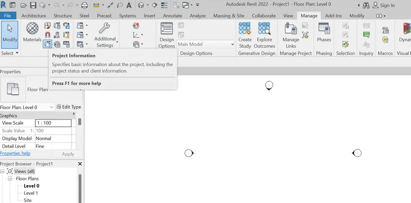
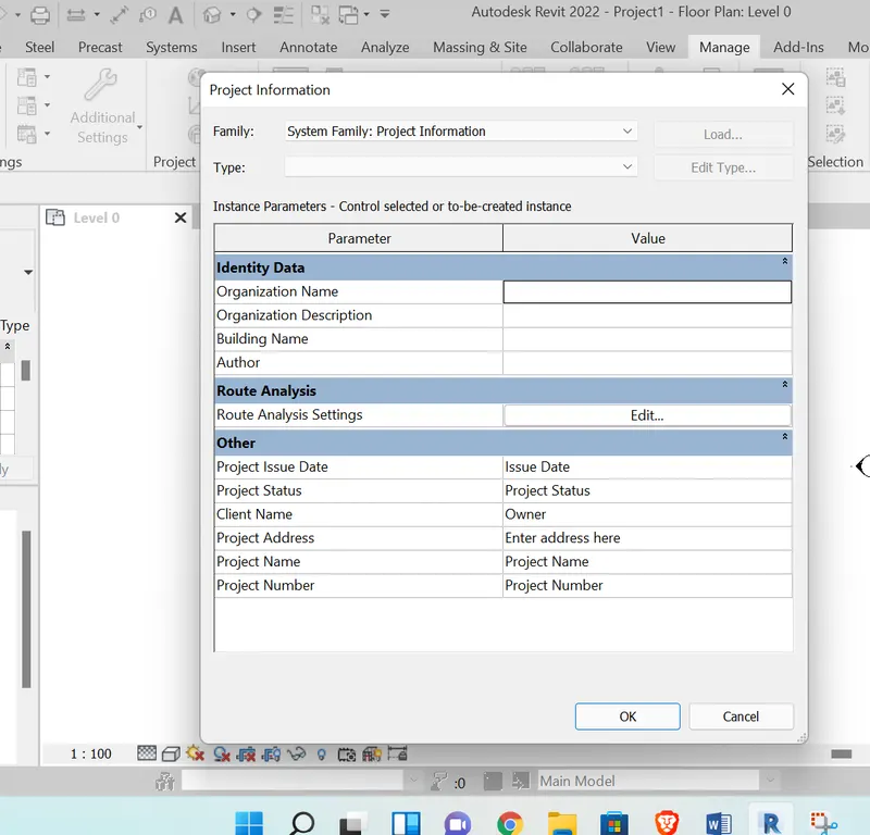
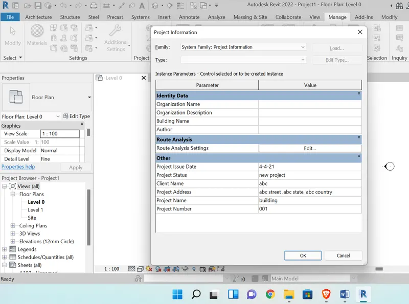
Enter details of the project in pop up tab
Result:
4) Understand the concept of Levels and Grids. Follow the naming and conventions. Create the following Levels: ( Convert to metric equivalents if metric is your units)
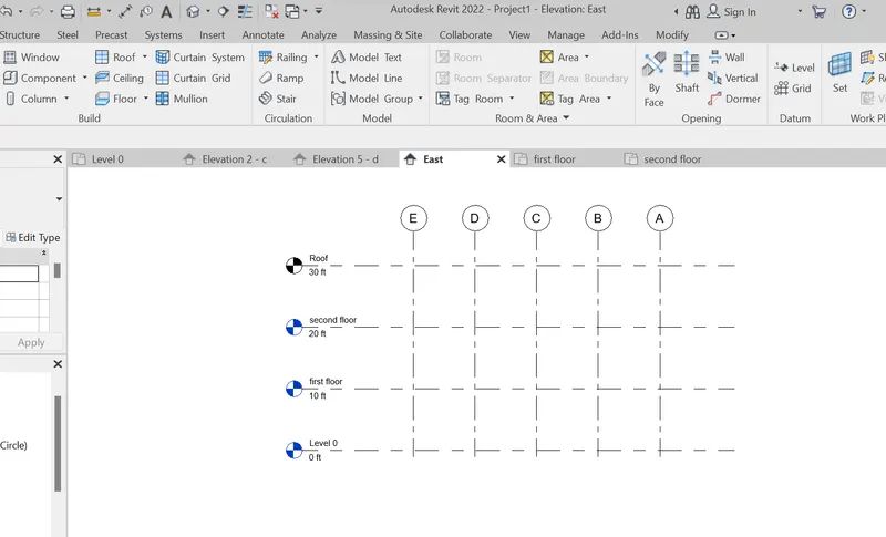
Ground Floor @ 0’
First Floor @ 10’
Second Floor @ 20’
Roof @ 30’
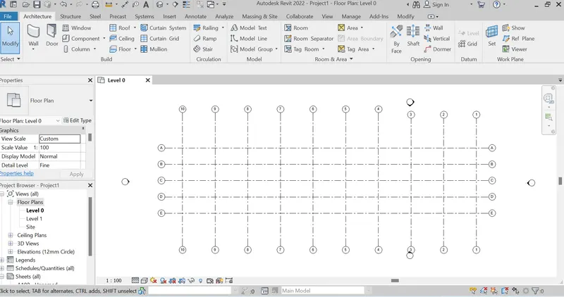
Grids Transverse Grids A, B,C,D, E @ 10’ spacing
Longitudinal Grids from 1 to 10 @ 20’ spacing
Ans:
- Creating a levels
- goto level option
- rename the level 0 - ground
- level1-first floor and change the inter distance
- select level option
- offset the level to 10ft and rename as second floor
- offset from previous level at distance 10ft and rename as roof
Create a gride lines
- select grid option specify point and direction as horizontal
- name as A
- select grid option again select array option enter no of grids as 4
- specify interdistance as 10'
- repeate the same steps for vertical grides
- note: while creating vertical grids the direction must be vertical
 .
.
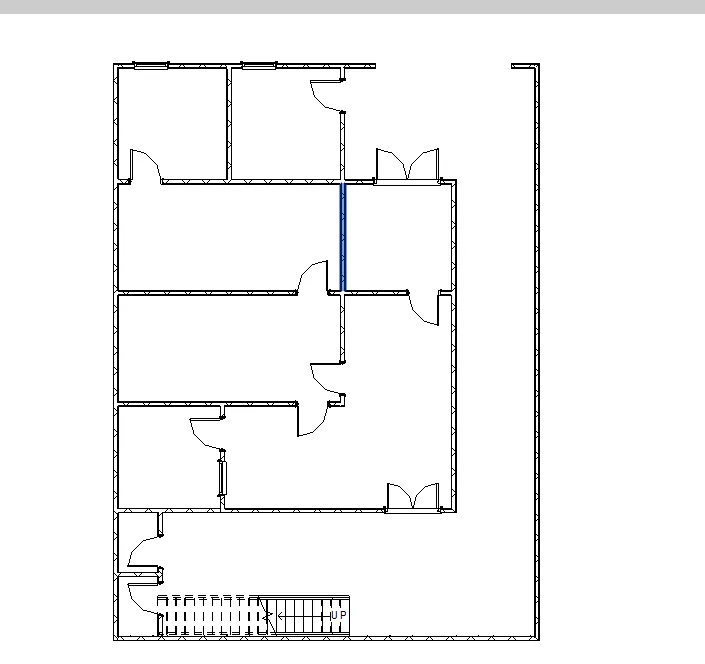
5) 3D modelling of residential unit – From looking at your house / or a place you aspire. Create a conceptual layout of the residential unit. You can measure using a tape or
you can access your residential plan to create a similar layout.
Ans :
- Open revit
- Change project units to feets
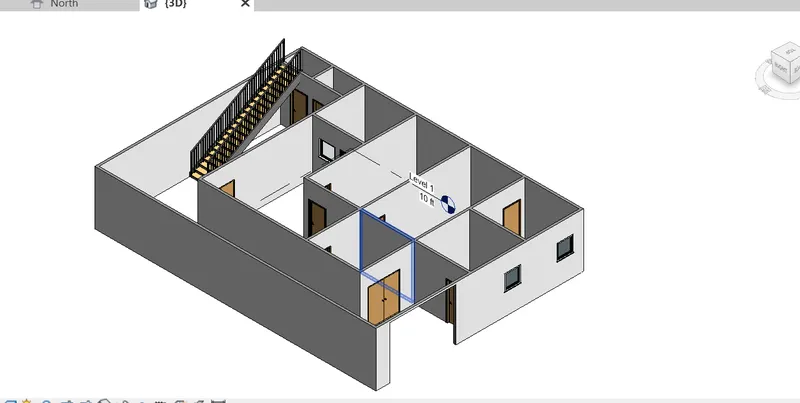
- Create the boundary wall
- Create room walls
- Insert doors by using door icon
- create stair case
- create level 1 at distance 10'
- select all the walls
- change the top constrain to level 1
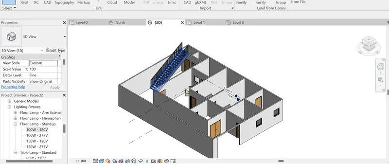
- select view tab switch to 3d view
Result:
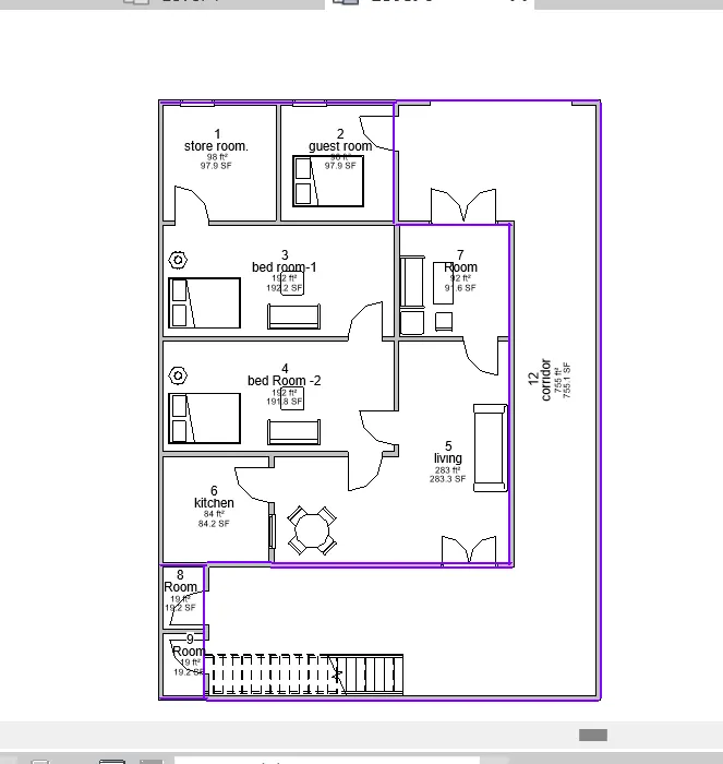
6) In the layout created draft the level of details you are planning to include – Dimensions of room, components you plan to add in the residential unit.
Ans :
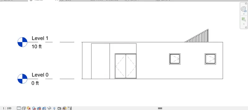
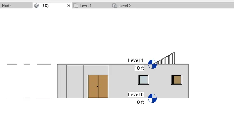
As per model level 1 is created at distance of 10' and the top constaint of the walls are up to level 1
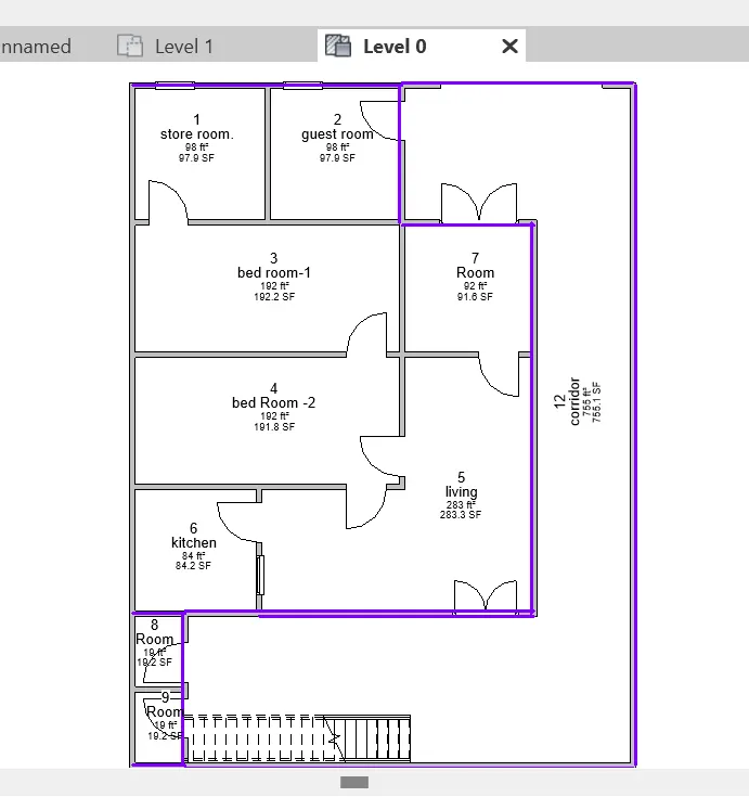
- Goto room option to create a room area
- and select the room and press enter
- Name the room
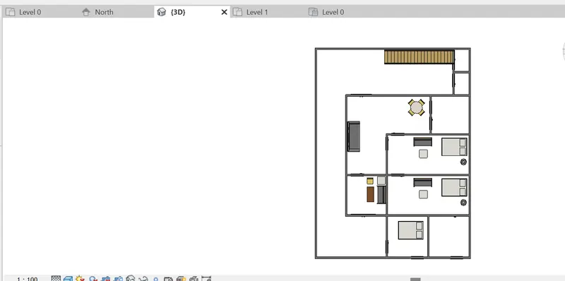
7) Identify the residential model elements such as Door, Windows, Tables, Chair, Couch, Bed, Lamps from the library and insert them to the model . Save the project for use
for Assignment 3
- Inset required elements from library which are not available in family
- Select INSERT tab
- select LOad family option
- search for required element in pop up tab
- select the element
- select to open
- The elements are loades in family
- we can find the elements in family
- select the element required
- right click
- click for create Instance
- specify the location in module
Result:
- 3D view of the drawing
Result: