Creating Levels, Grids, Layout and model elements for a residential unit using REVIT
1) What is BIM? Summarize the features of BIM and benefits of using BIM over 2D CAD tools.
ANSWER:
BIM is defined as a Building Information Modeling process.
It is one of the most advanced technology that is being implemented in the architectural, structural, and MEP designs of a project model. It plays a major role in the AEC industry.
BIM is divided into two main core concepts in order to achieve the maximum flexibility and efficiency in designing of a 3d project. They are named as follows: -
- Coordination
- Computation
The coordination process in the BIM organizes the different elements of a family into one category and it enables them to work together effectively.
Computation process includes the material properties, quantity schedules and it helps in achieving the performance and evaluation of energy analysis of the building.
Therefore, autodesk revit is a BIM tool that helps in achieving the coordination and computation of a project.
FEATURES AND BENEFITS OF THE BIM OVER 2D/3D CAD TOOLS: -
FEATURES ASSOCIATED WITH THE BIM: -
- It functions smoothly and doesn’t affect to the real time changes.
- It helps in achieving the evaluation and performance of energy analysis of a building.
- It optimizes the use of the resources in the building.
- It provides the sustainability.
- It also offers the parametric designing of the project model.
BENEFITS ASSOCIATED WITH THE BIM: -
- It improves the onsite collaboration and communication.
- Avoids the duplication of elements.
- It offers the parametric design features.
- Avoids uncertainity.
- Evaluation and performance of energy analysis.
- It optimizes the risk and reduces the cost.
- It schedules the quantities.
- Creates the scope for future.
- Highly scope for the structural engineers.
2) Understand the concept of Categories, Families, Elements, Instances in Revit. Go to Insert Tab, choose a category. Pick a family and element. Understand the instances and insert it to Revit model.
ANSWER: -
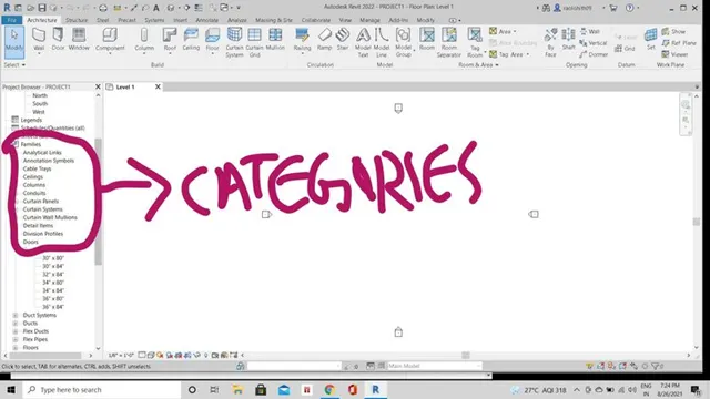
CATEGORIES: -
A category defines and controls the organization, representation, scheduling options of families within the project.
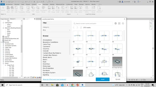
FAMILIES: -
A family is termed as a grouping of 2d/3d building components. Under the insert tab, a group of autodesk family is loaded which consists of so many autodesk components such as door, structural components etc....
ELEMENTS: -
The elements are defined as a grouping of a particular family component into different terms and sizes. It is a three-dimensional model visible in all the 2d and 3d model views.
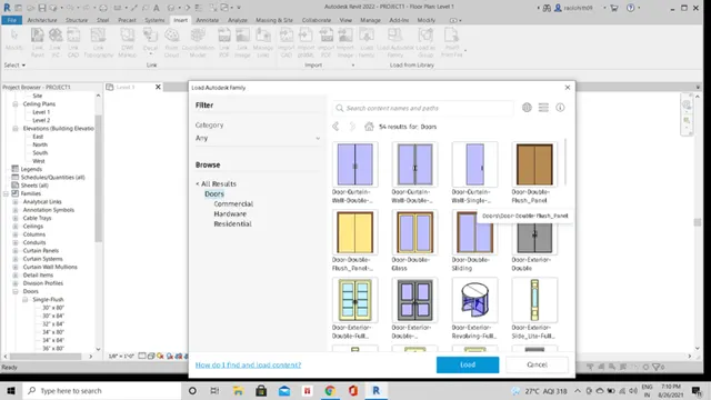
Example: -
A door-double-flush_ panel is an element under the family of door.
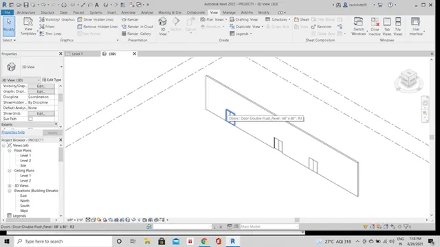
INSTANCES: -
Instances are the individual representation of an element in a project such as door, window e.t.c....
A door-double-flush_ panel is an element inserted to the model in a project.
3) Setting up a Project – Open a project file with architectural template. Save the file with appropriate name. Set up the project units to Imperial / Metric based on your convenience of modelling. Complete the project information under Manage tab. Set up the maximum backups for project file to 3.
AIM: -
To open a project file with architectural template and saving it with an appropriate name, and setting the project units to imperial and providing the project information under managetab and setting up backups for the project files maximum to 3.
PROCEDURE: -
- To open a project file with architectural template. Click on the open new file and select the architectural-imperial template.
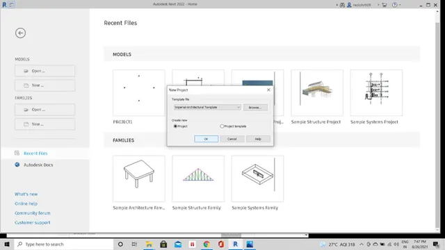
- Click ok.
- Go to the file tab and save as icon option to save the file.
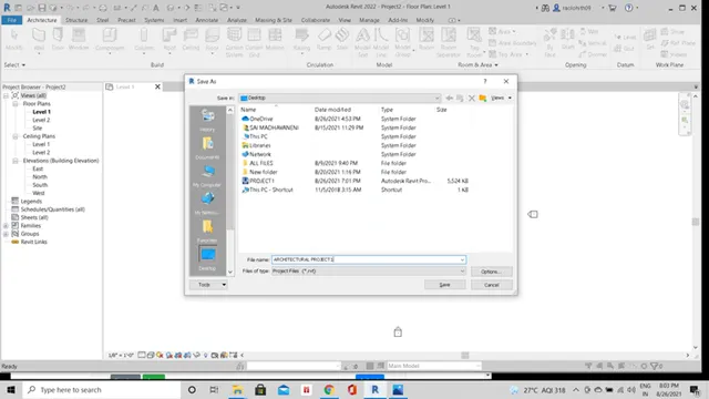
- Name the file as architectural project1.
- Click on save.
- The file is named and saved to the local folder.
- Go to the manage tab and click on project information icon to provide the project details such as project name, issue date.
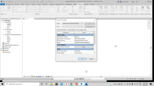
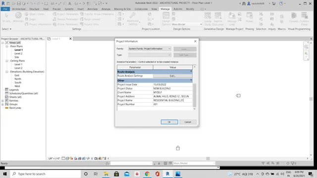
- To setup the maximum backups, go to file tab and under the save as icon click on the options.
- By default, revit backups the files maximum up to no.3.
- The backup files are used to restore the files when the files get trashed/removed.
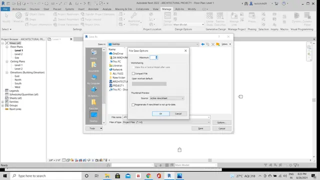
- Click ok.
RESULT:
Hence, the new architectural imperial template file is saved and named as architectural project1 and the project information is assigned to the file created and also created the maximum no. Of backup files to 3.
4) Understand the concept of Levels and Grids. Follow the naming and conventions. Create the following Levels: (Convert to metric equivalents if metric is your units)
Ground Floor @ 0’
First Floor @ 10’
Second Floor @ 20’
Roof @ 30’
Grids Transverse Grids A, B, C, D, E @ 10’ spacing
Longitudinal Grids from 1 to 10 @ 20’ spacing
AIM: -
To understand the concept of levels and grids and cresting the levels at ground floor @ 0', first floor @ 10', second floor @ 20' and roof @ 30'.
PROCEDURE: -
LEVELS: -
Levels in the revit are useful to indicate the floors, foundations, and roof of a building in section and elevation views.
GRIDS: -
Grids are defined as the reference lines that are useful for while designing and modeling the building.
STEPS TO CREATING THE LEVELS OF FLOORS AT DIFFERENT FEETS MENTIONED ABOVE: -
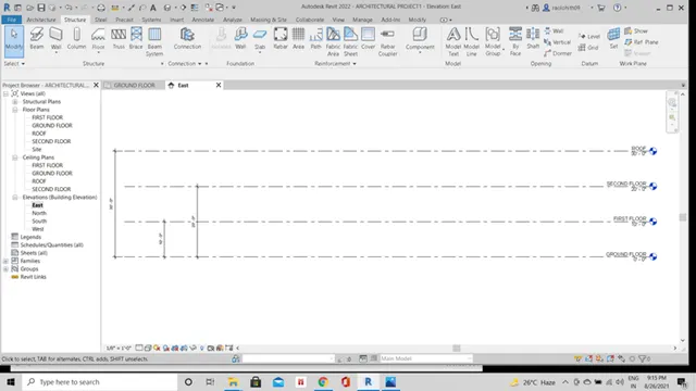
- Go to the any elevation view such as north, south, east, or west.
- Select the east elevation and the two levels appears on the window.
- By default revit has two levels created at the difference height of 10' between the two levels.
- To create the level ground floor at a base datum at 0' double click on the level name at datum level and edit the level to ground floor.
- At the level 2 which is created by default at a height of 10’, double click on the level name and edit as the first floor.
- Next, we have to create a new level at height of 10’, to do that go to structural tab and under datum click on the level icon.
- Then click on the below level as reference and create a new level at a height of 10’.
- The second floor at a height of 20' from the ground floor is created.
- From the bottom reference level I . e, second floor create a new level at height of 10'.
- A new layer is created at a height of 30' from the ground floor and name the layer as roof.
STEPS TO CREATE GRIDS ALONG TRANSVERSE A, B, C, D, E @ 10' SPACING: -
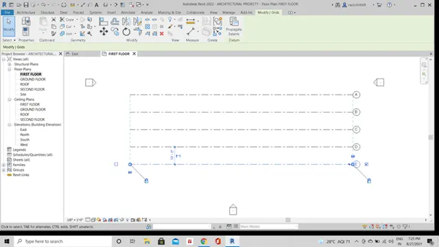
- To create the grids, go to the any selected floor under the floor plans and go to structural tab and under the datum section select grids.
- Create the grid along traverse direction at a particular point in the modelling space.
- From the grid created by taking it as reference create the grids at an offset of 10' distance by clicking on pick lines.
- After creating the grids assign the alphabetical names to the transverse grids and the naming should be provided from the top to bottom.
- Therefore, the grids a, b, c, d, and e are created along transverse direction at 10' spacing.
STEPS TO CREATE GRIDS FROM 1 TO 10 ALONG LONGITUDINAL DIRECTION @ 20' SPACING: -
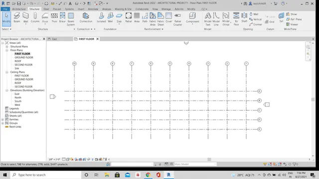
To create the longitudinal grids, as similar to the above transverse grids create a grid along longitudinal direction at the modeling space.
By clicking on pick lines option provide an offset of 20' from the reference grid and create multiple grids parallel to it.
After creating the multiple number of grids along longitudinal direction, assign the numerical numbers to the grids from right to left order.
Therefore, the grids 1 to 10 is created along longitudinal direction at the spacing of 20’.
RESULT: -
Hence, the levels with respect to each floor are created at the respected given heights, and the grids along transverse and longitudinal direction are created with respective their spacing mentioned above.
5) 3D modelling of residential unit – From looking at your house / or a place you aspire. Create a conceptual layout of the residential unit. You can measure using a tape or
you can access your residential plan to create a similar layout.
AIM: -
To create a conceptual layout of residential plan.
PROCEDURE: -
- Measure the dimensions of the layout of residential unit and convert it to the required unit format.
- Open the new revit file by using a construction -imperial template.
- Save the file as first new residential project.
- Assign the project information in the manage tab.
- Set the geographical location in the manage tab.
- Go to the structural tab and select the architectural floor under the floor icon.
- Draw the layout sketch of residential floor plan according to the layout dimensions by using the line icon under the draw panel.
- Then click ok.
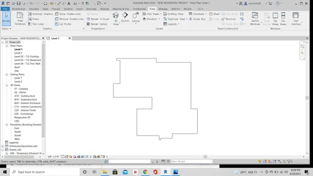
RESULT: -
Hence, the conceptual layout of the residential plan is created.
6) In the layout created draft the level of details you are planning to include – Dimensions of room, components you plan to add in the residential unit.
AIM: -
To draft the level of details in the layout model created.
PROCEDURE: -
- For dimensioning the rooms, first the layout created should be assigned with the wall boundaries.
- Drafting the walls along the layout of the model created.
- Go to the structural tab and click on architectural wall under the wall icon.
- Select the pick lines icon under the draw panel tab.
- Create the walls along the layout sketch of the residential floor plan by selecting the lines wherever it is required.
- Draw the partition walls in between the layout by providing the offsets.
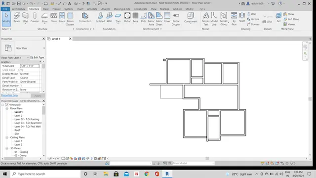
- The partitions walls created a closed boundaries in the layout.
- To determine the room and its dimensions the boundaries created must be closed and if it is open at any ends click on the room separator icon and draw a line to form a closed loop.
- For dimensioning the closed boundaries created in the layout click on the room icon under architectural tab, and the place it on the closed boundaries to determine the room and its dimensions.
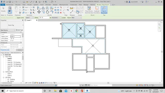
- The rooms are created along with the dimensions, edit the rooms with the proper names in the layout.
- To add components to the model, load families that is required from the insert tab and select the families that is installed in the specified location in the pc.
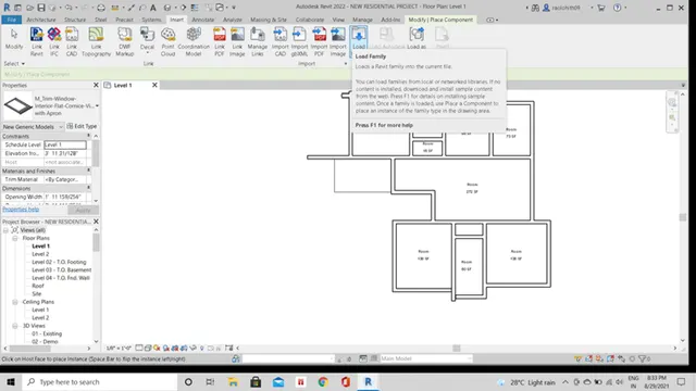
- After creating the rooms if we want to tag an additional closed boundary go to the annotate bar and under that click on the room tag option.
RESULT: -
Therefore, the rooms are created in the layout and the dimensions of the room is assigned to the created layout model and the component names of the rooms is assigned to the model.
7) Identify the residential model elements such as Door, Windows, Tables, Chair, Couch, Bed, Lamps from the library and insert them to the model. Save the project for use
for Assignment 3
AIM: -
To add the residential model elements such as door, tables, windows, chair, couch, bed, lamps from the library and inserting them to the model.
PROCEDURE: -
- To create any model element, click on the architectural tab and choose a specific element under the tab such as door, window and create them along the model.
- If we require additional model elements load it from the family under the insert tab and save it to the project browser under the families category.
- And from there choose the required model element and its instances and place it along the model.
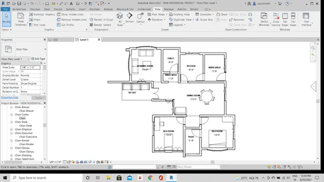
- If necessary to edit the dimensions of the elements, select the element and choose edit type under the properties browser and place it along the model.
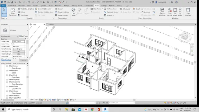
- Click on the 3d view.
- Click on the 3d realistic view.
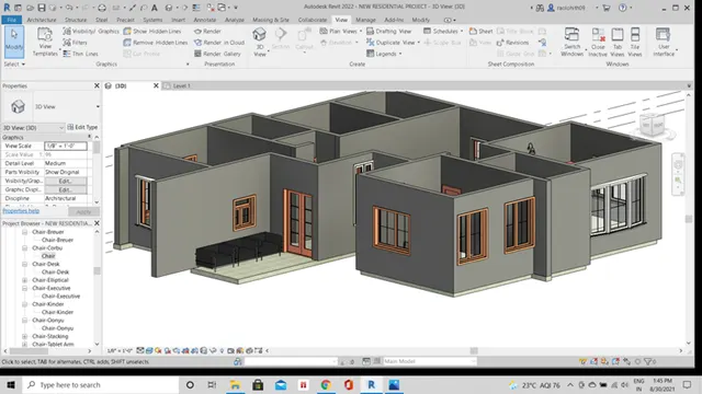
- After inserting the model elements such as door, windows, chair, couch, bed, lamps, save the model for the further use.
- Click on save option.
RESULT:
Hence the residential model elements are added and inserted into the model and it is saved for the further use.