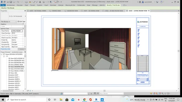
3D Creation of Celing, Roof, Architectural plan, Structural plan, Sectional view, Elevation view and Camera specific view for a house plan using REVIT
1)
Based on the project saved from Week 3, proceed from the First Floor Level. Model a Ceiling from the architecture tab above the walls at the first-floor level.
AIM: -
To model a ceiling above the walls at the first-floor level of the residential project.
PROCEDURE: -
- To model a ceiling at the first-floor level of the residential unit, select the ceiling icon under the architecture tab.
- Choose the type of the ceiling from the property’s browser and model along the boundaries of the rooms at the first-floor level.
- Model a compound ceiling of mtl. stud type by sketching the boundary layout of the living and dining area using pick lines icon/ lines under modify tab.
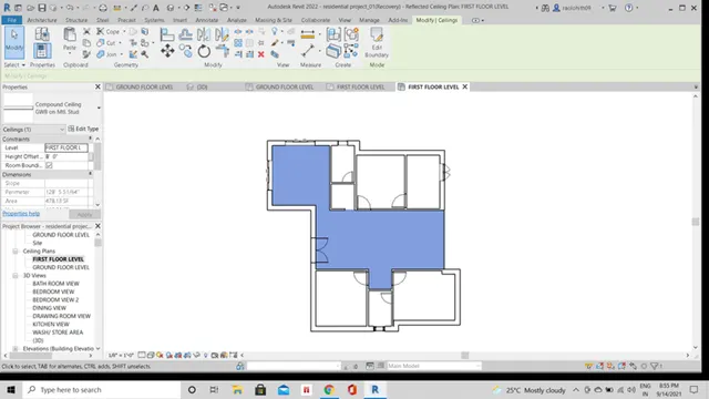
- Create an automatic compound ceiling along the boundaries of remaining rooms of type act system.
- For toilets create a ceiling of 2'*2' compound act system and for bedroom and kitchen area model a ceiling of compound act system of 2'*4'.
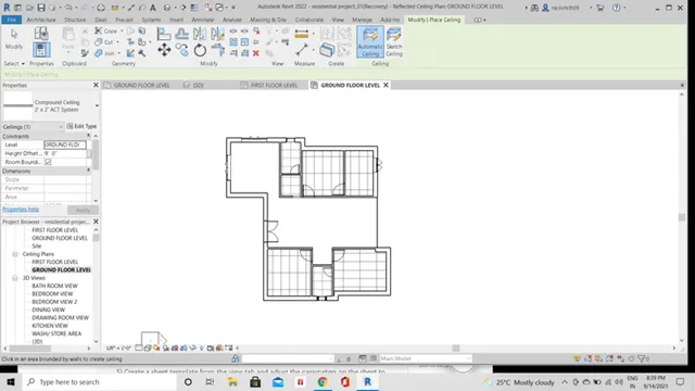
- Hence, the ceiling is modeled at the first floor of the residential unit.
RESULT: -
Ceiling types modelled: -
Compound ceiling of mtl. stud.
Compound ceiling of 2'*2' act system.
Compound ceiling of 2'*4' act system.
The modeling of ceiling at the first-floor levels above the walls is laid, hence the residential unit is now provided with the ceiling at above the walls of the first-floor level.
2)
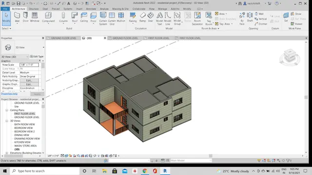
Model a roof above the ceiling by selecting the footprints of the ceiling. Using the adjustment toolbars appearing on-screen adjust the roof slope to 10 degrees
AIM: -
To model a roof above the ceiling by selecting the footprints of the ceiling and adjusting the roof slope to 10 degrees by using the adjustment toolbars.
PROCEDURE: -
- To model a roof above the ceiling created, click on the roof icon under the architecture tab.
- Select the roof type as roof by footprint.
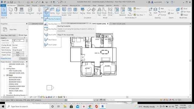
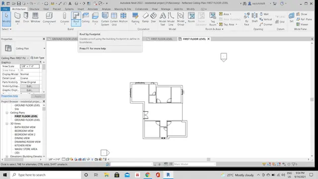
- Model a roof by picking the lines of the footprints of ceiling by using the lines/ pick lines icon under the modify tab.
- Provide the base offset as 10'.
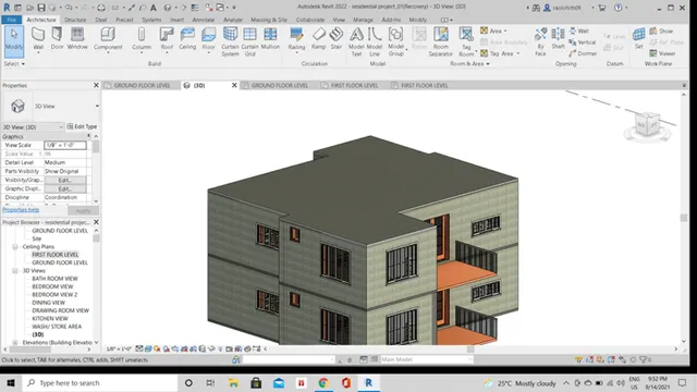
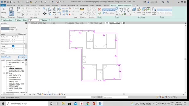
- Adjust the roof slope to 10 degrees by clicking on the slope icon displayed on the screen window.
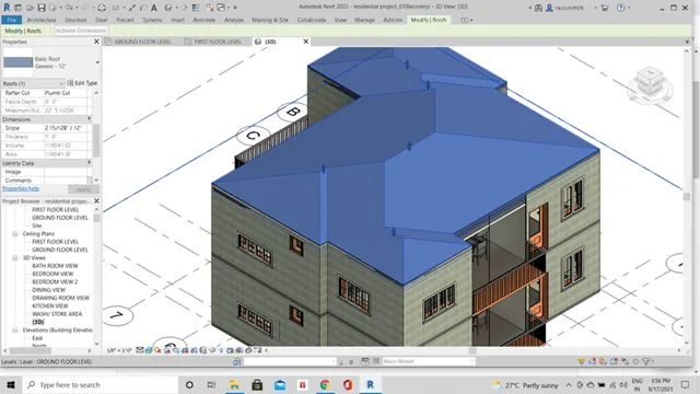
- Hence the roof of the slope is adjusted to 10 degrees by using the adjustment toolbars.
RESULT: -
Type of roof modeled:
Basic generic roof of 12".
The roof is modeled above the ceiling created and adjusted to the slope of 10°.
3)
Using the file saved from weeks 2 to 4, create plan views for ground floor level and first-floor level including all the walls, floors, and components. Separate them to
architecture and structural plans
- Architecture plan must have walls, floors, and all the components placed within the building
b. Structure plan must have details of only walls, floors, and columns
AIM: -
To create the plan views for ground floor level and first-floor level including all the walls, floors, and components...and separate them to architectural and structural plans.
INTRODUCTION: -
The architectural plan includes all the components placed in the building at different floor levels.
The structural plan includes only the structural components modeled in the building.
PROCEDURE: -
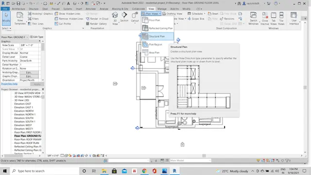
- To create the plan views for ground floor level and first-floor level of building, click on the view tab.
- Under the view tab, click on the plan views icon.
- Under the dropdown of plan views icon select the type of plan to be created.
- The architectural plan view is the default view modeled in the project.
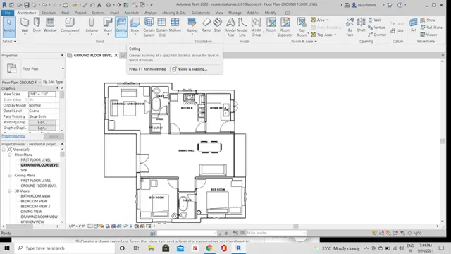
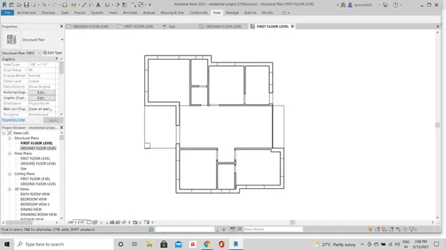
- To create the structural plans of first-floor level and ground floor level click on the structural plan icon, and create the structural layouts of first-floor level and ground floor level respectively.
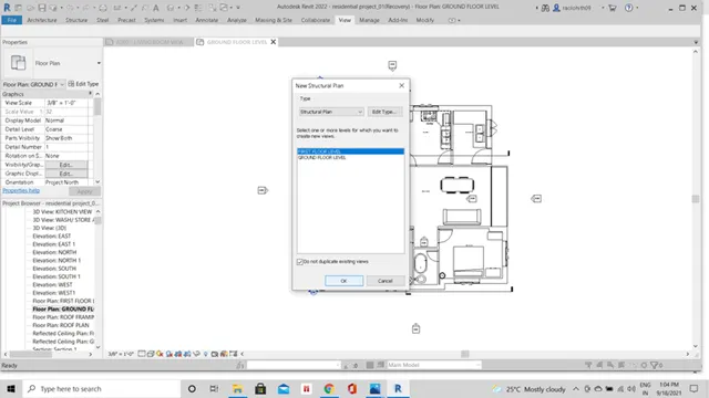
- Click ok.
- The structural plan layout of the first-floor level is modeled.
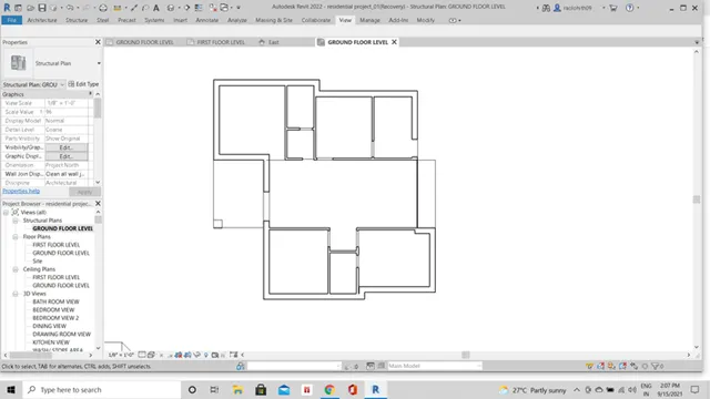
- Similarly, model the ground floor structural plan layout of the building.
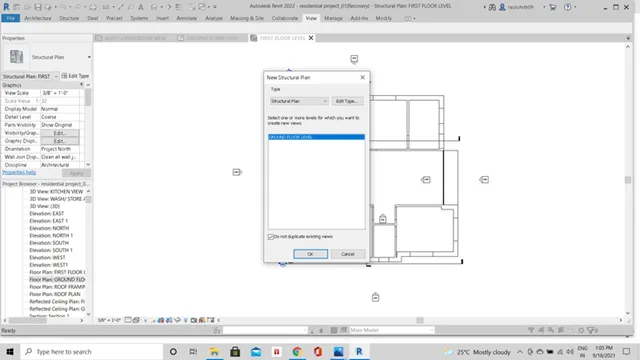
- Click ok.
- Hence, the structural plan layout of the ground floor level is created.
RESULT: -
The plan views of ground floor level and first-floor level are modeled.
The structural plan views include only the structural components of the building.
The architectural plan views include all the components placed in the building.
4)
Using annotate toolbar add dimensions to all the walls and floors with reference to the longitudinal and transverse grids created in the project file
- The architecture plan dimensions include details on where the components are placed within the buildings with relation to grids. Overall dimensions are sufficient for architecture plans
- The Structure plan dimensions must include details on the position of all the walls and interior walls with reference to grids. Locate all the framing components of the building with reference to a fixed point using Structural plans
AIM: -
To create the transverse and longitudinal grids in the project and annotate the dimensions to all the walls and floors with reference to the grids by using the annotate toolbar.
INTRODUCTION: -
The transverse and the longitudinal grids can be act as the referencing lines to the project.
Annotate toolbar is used to assign the dimensions to the layout plans created in the project.
PROCEDURE: -
For placing the longitudinal and transverse grids in the project, click on the grid icon under the architectural view tab.
Place the transverse and longitudinal grids along the architectural and structural plan views to align the dimensions for the layouts created.
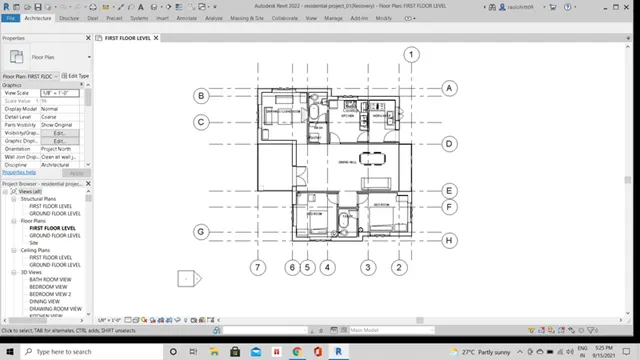
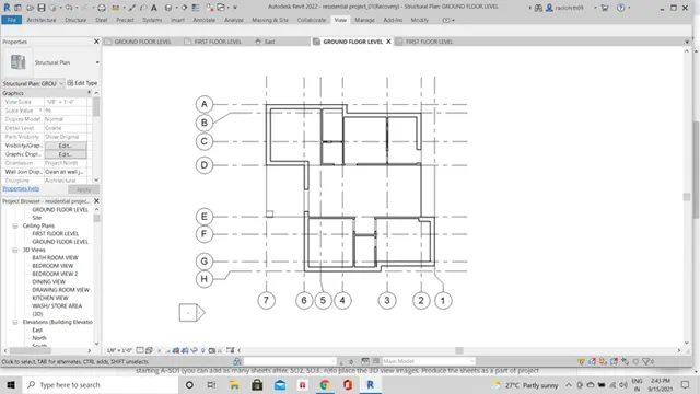
After modeling the grids along the plans, click on the annotate toolbar to assign the dimensions with reference to the grids placed.
- a) Dimensioning of architectural view plans: -
Click on the ground floor and first-floor architectural plans and assign the overall dimensions for the layouts.
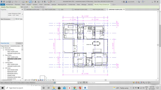
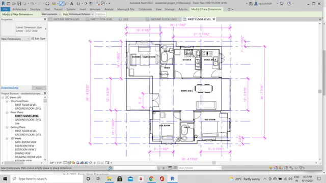
- B) Dimensioning of structural view plans: -
Click on the ground floor and first-floor levels of the structural view plans and assign the dimensions to the components placed in the structural layouts.
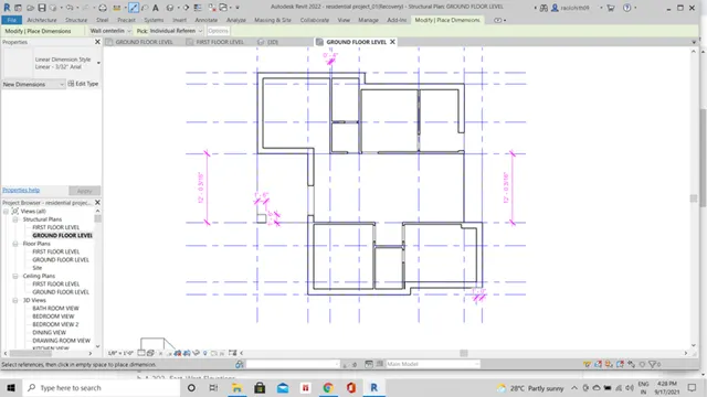
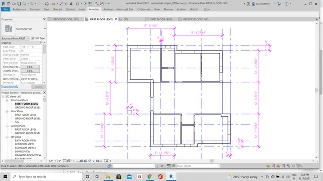
Here, in the structural plan views of the ground floor level and the first-floor level we have assigned the dimensions to only the structural components placed in the building.
RESULT: -
The longitudinal and transverse grids are created along the ground floor and first-floor levels of the different plan views.
The architectural plan views are provided by the overall dimensions of the layout with reference to the transverse and the longitudinal grids.
The structural plan views are provided by the dimensions of only structural components placed in the building with reference to the transverse and longitudinal grids.
5)
Create a sheet template from the view tab and adjust the parameters on the sheet to add appropriate views
AIM: -
To create a sheet template and adjust the parameters on the sheet to add appropriate views by using the view tab.
PROCEDURE: -
Click on the view toolbar.
Under the view toolbar click on the sheet icon.
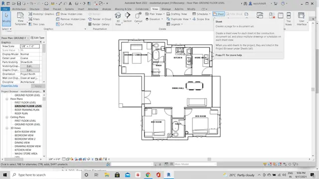
The sheets containing dialog box appears on the window, and by default revit as only few sheets created.
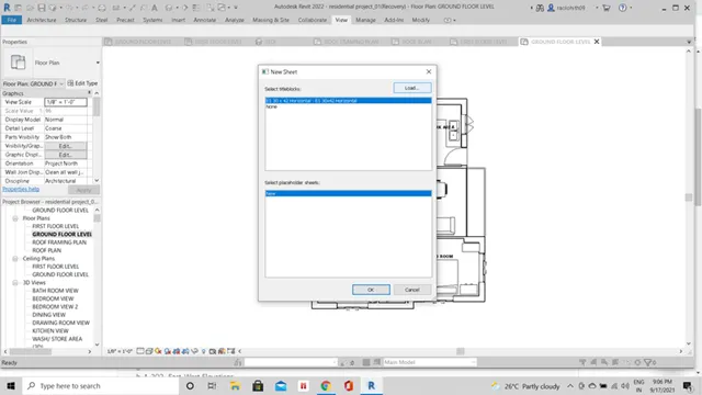
To add the extra sheets into the project, click on the load button and choose the type of sheets from the title blocks loaded in the revit family.
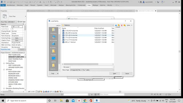
Here, we have selected the sheet of d22*24 horizontal and loaded into the project.
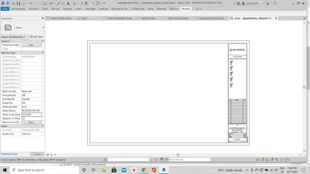
A new sheet with the default name as a-101 is created in the project.
We can adjust the parameters of the sheet by using the properties browser or the parameters can be adjusted within the sheet by editing the values.
RESULT: -
A new sheet template of d22*24 horizontal is loaded into the project.
Sheet template is named as a-101.
The parameters such as sheet name, numbers and views are adjusted within the sheet layout.
6)
Using the elevation tab create the elevation views, looking at you’re building from East, North, South, and West
AIM: -
To create the east, north, south, and west elevation views using the elevation tab.
PROCEDURE: -
To create any elevation view in the project, click on the view toolbar.
Under the view toolbar, click on the elevation tab.
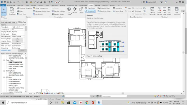
By looking at the building create the elevations along the east, north, south, and west directions.
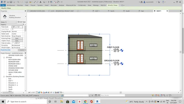
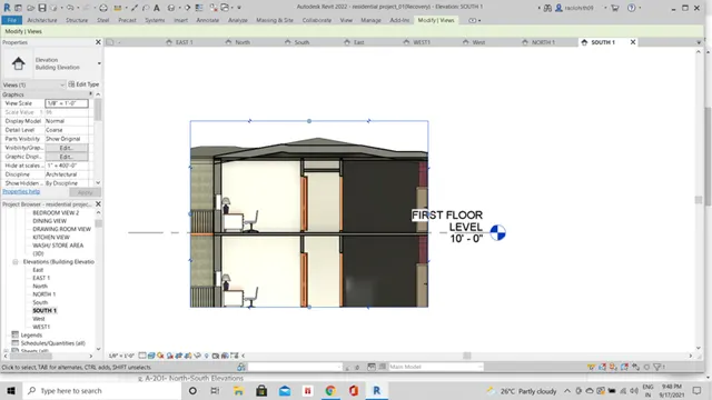
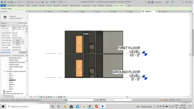
Name the elevations created as east1, north1, south1, and west1 by renaming in the project browser.
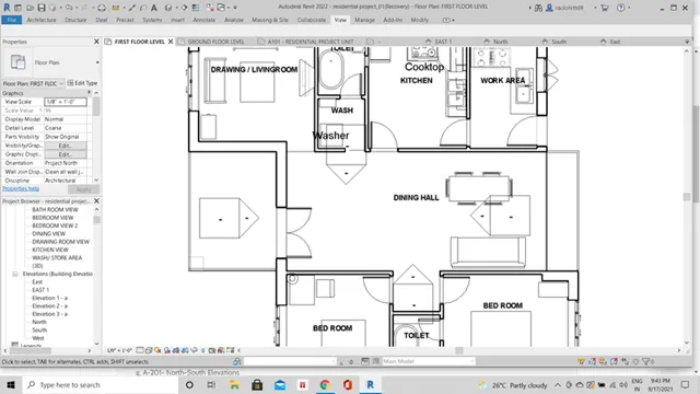
Hence, the elevations are created along all the directions of the building and named as east1, north1, south1, and west1.
RESULT: -
The east1 and west1 elevation views created are as follows: -
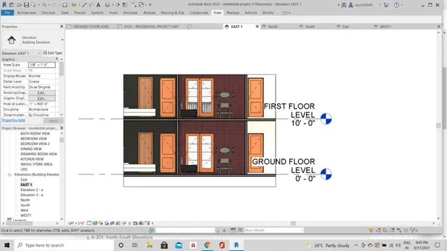
The north1 and south1 elevation views created are as follows: -
7)
Produce section cut through each room either cutting across longitudinally or in a transverse direction
AIM: -
To produce the section cuts through each room either cutting across longitudinal or transverse in direction.
PROCEDURE: -
To create the section cuts through the rooms, click on the view toolbar.
Under the view toolbar, click on the section tab.
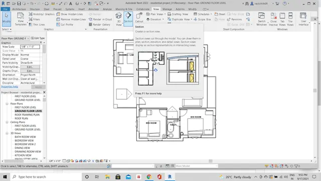
Create the sections longitudinally or transverse in direction along the layout.
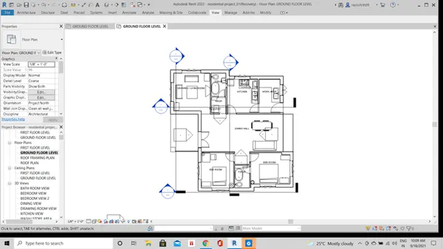
The sections are created along the layout longitudinally and transverse in direction.
RESULT: -
Hence, the sectional views are created through the rooms along longitudinal and transverse in direction.
8)
Classify the views, Plan Views, Section Views, and Elevation views to either Design or Documentation category using Properties browser
AIM: -
To classify the views, plan views, section views, and elevation views to design category using the properties browser.
PROCEDURE: -
To classify the views into a design category, click on the manage tab.
Under manage tab, click on the project parameters icon.
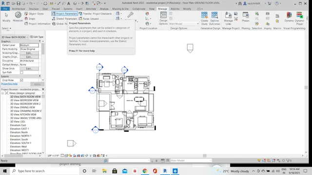
Enter the parameter data as design category, and the parameter type as text and select the group parameter as graphics.
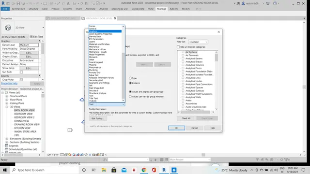
Select the view box under the graphics category.
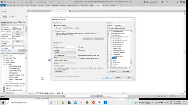
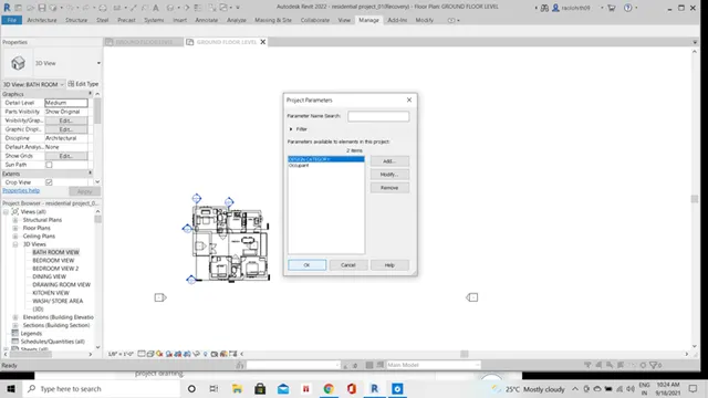
The design category parameter is created.
Now, in the project browser, right click on the views all icon.
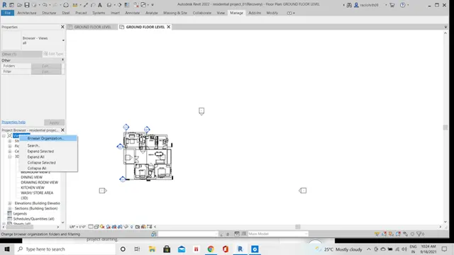
Click on the browse organization, and select the design category parameter.
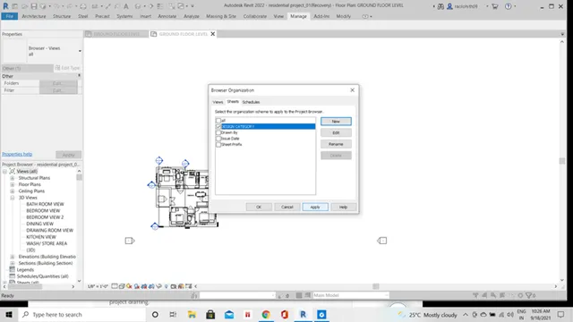
Click apply and ok.
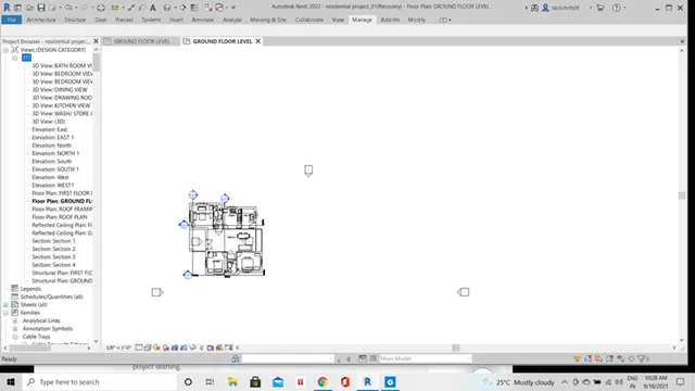
Now all the views are classified under the design category family.
RESULT: -
All the plan views, section views, elevation views .... are classified to the design category in the project browser.
9)
Using the sheet template produced create multiple sheets as follows
a. A 101- Ground Floor Architecture Plan
b. A 102- First Floor Architecture Plan
c. A 103- Roof Plan
d. S 101- Ground Floor Structural Plan
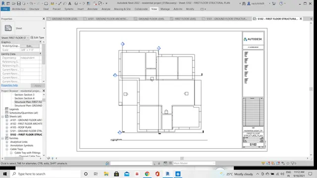
e. S 102- First Floor Structural Plan
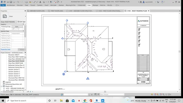
f. S 103- Roof Framing Plan
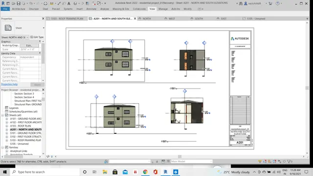
g. A-201- North-South Elevations
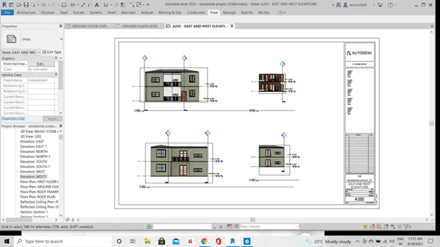
h. A-202- East-West Elevations
Add additional sheets based on the sections created in your Revit file
AIM: -
To create the sheet templates and the sheet names for the different plan views in the revit file.
PROCEDURE: -
To create a sheet template, click on the view toolbar.
Under view toolbar, click on the sheet’s icon.
The sheets containing dialog box appears on the screen and choose the sheet template of d 2'*2' horizontal.
Now create the multiple sheets similarly and name the sheets according to the plan views added to the sheets.
Adjust the plan views to the sheet size by changing the view scale in the property’s browser.
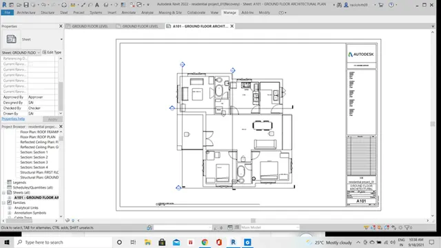
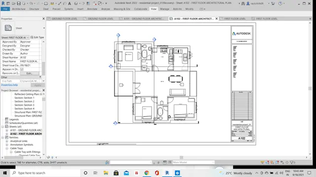
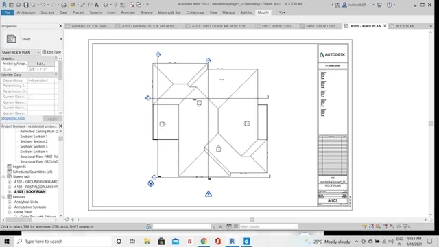
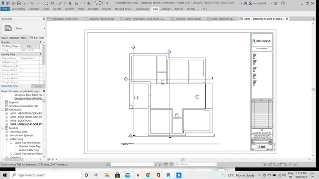
The multiple sheets that are created as follows: -
A)
A 101- ground floor architecture plan sheet: -
B)
A 102- first floor architecture plan sheet: -
C)
A 103- roof plan sheet: -
D)
S 101- ground floor structural plan: -
E)
S 102- first floor structural plan: -
F)
S 103- roof framing plan: -
- G)
A 201- north-south elevations sheet: -
F)
A 202-east-west elevations sheet: -
G)
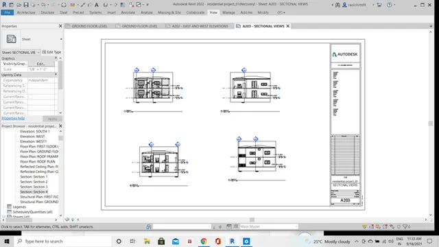
A 203- sectional views sheet: -
RESULT: -
Hence, for all the plan views the multiple sheets have been created and named according to the plan views in the revit project file.
10)
Create a camera-specific view or a 3D view in each room (living, dining, bedroom). Based on the views create a new set of sheets starting A-501 (you can add as many sheets after, 502, 503. n) to place the 3D view images. Produce the sheets as a part of project drafting.
AIM: -
To create a camera-specific view or a 3d view in living, dining, bedroom, and based on the views creating a new set of sheets to place the 3d view images.
PROCEDURE: -
To create a camera -specific view for the living, dining, and bedroom click on the view toolbar.
Under the view toolbar click on the camera and place it along the rooms.
Click on the 3d view.
Create a new sheet by clicking on the sheet icon.
Select any of the sheet template and drag the 3d views created of living, dining, and bedroom to the sheets and change the sheet numbers accordingly.
RESULT: -
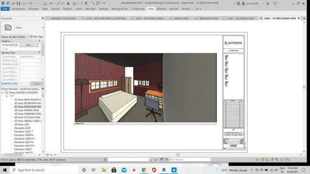
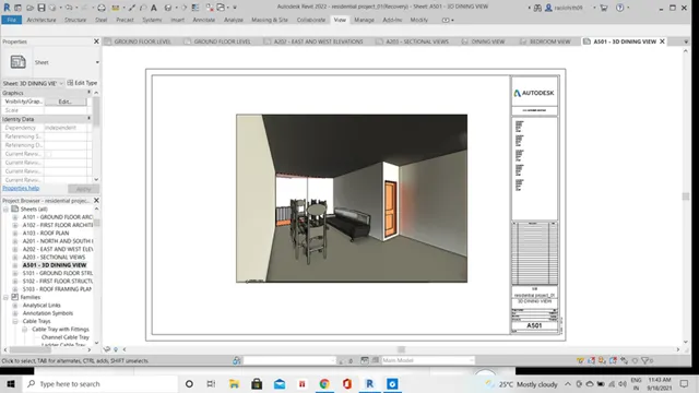
THE 3D VIEWS OF THE SHEETS CREATED ARE AS FOLLOWS: -
A)
3D VIEW OF A 502- BEDROOM SHEET: -
B)
3D VIEW OF A 501- DININGROOM SHEET: -
C)
3D VIEW OF A 503- LIVINGROOM SHEET: -