Introduction to REVIT concepts
1)
AIM:
To create and name a new architectural template project file from the file menu.
PROCEDURE:
- Open the revit software.
- Click on the file menu located on the top left of the window.
- Select the new icon from the file menu.
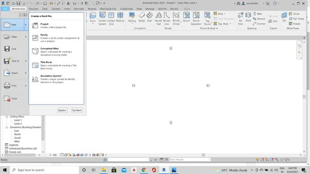
- Select the project icon to create a new revit file.
- Creation of new project dialog box appears on the window.
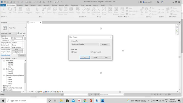
- Choose an architectural template from the dropdown of template file.
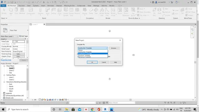
- Click ok.
- Then select project.
- Click ok.
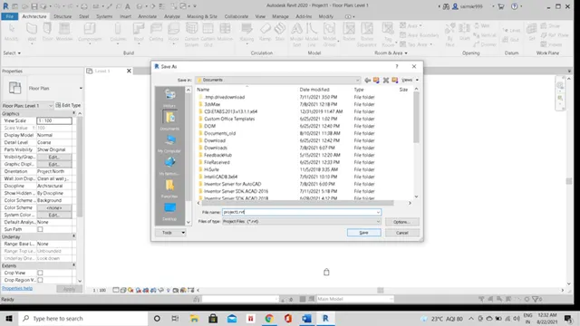
- To name the project click on the file toolbar.
- Click on the option save as.
- Name the project file has project1.rvt.
RESULT:
A new architectural template project has been named and created as project1.rvt.
2)
AIM:
To save a new file and open & close a file using the file tool bar.
PROCEDURE:
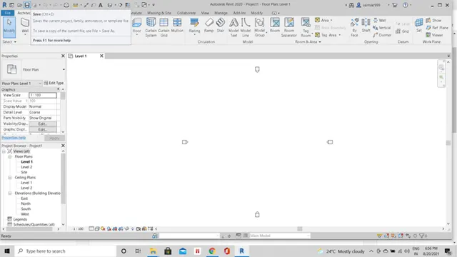
- Click on the save button displayed on the quick access bar on the top left side.
- The "save as" dialog box appears on the screen.
- Enter the file name as basic architectural template.rvt
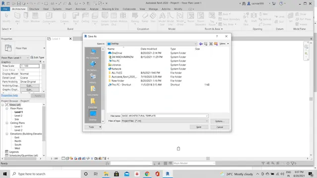
- Click the save button.
- The file is saved on the specified location of the pc.
- To open a file by using the file tool bar, click on the file tool bar.
- Under the file menu, access to the icon named "open".
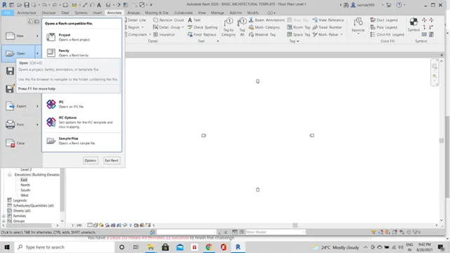
- Click on the project option to open a created revit project file.
- Open file dialog box appears, here enter the file name created that has been saved in the specified local folder.
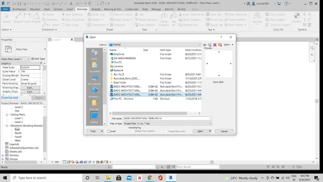
- Click on open the new revit project file which has been created is opened.
- To close the opened file, click on the file tool bar and access to the icon named "close".
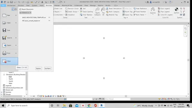
- Click on the close icon to close the file.
RESULT:
A new project has been saved in the name of basic architectural template.rvt and by using the file toolbar we opened and closed a file.
3)
AIM:
To draw a wall from the architectural toolbar and create a layout of rectangular walls of 40' * 35'.
PROCEDURE:
- Click on the architectural toolbar.
- Click on the wall icon to draw a wall under the architectural toolbar.
- The wall can be created by using the draw tool line in the ribbonbar under the modify/place tab.
- Click on the line and specify the first point and the last point to create a wall along both horizontal and vertical direction.
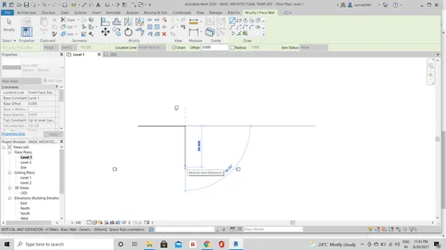
- To create the rectangular layout of walls 40'*35’, click on the rectangle in the ribbon bar of draw tool.
- Specify two corner sides of the rectangle and create the layout of rectangular wall, and then double click on the dimension of the walls and set to 40 ' along horizontal and 35' along vertical.
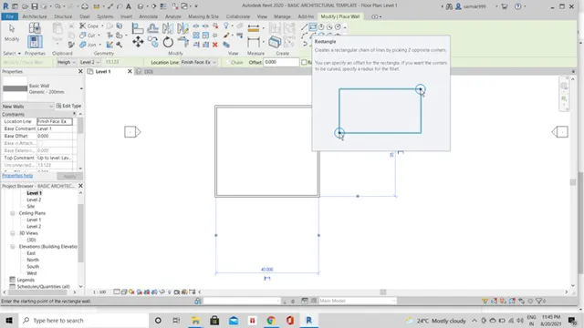
RESULT:
Therefore, the sample wall and rectangular layout of walls 40'*35' has been created by using the architectural toolbar.
4)
AIM:
To align the dimensions to the created rectangular layout of walls.
PROCEDURE:
- Click on the annotate bar.
- Select the aligned dimension style under the annotate bar.
- Measure the dimension between the two sides of the rectangular walls by placing at between two corner sides.
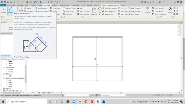
RESULT:
Hence, the dimensions to the layout have been added by using the aligned dimension from the annotate toolbar.
5)
AIM:
To switch to the different wall types by using the properties browser.
PROCEDURE:
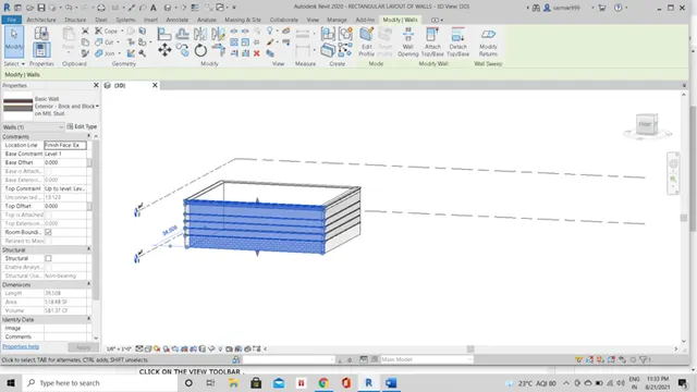
- Click on the view toolbar for the 3d view of the model.
- Select any rectangular face of the wall and assign the properties to the wall by switching to all the walls by using the properties browser.
RESULT:
Hence, by using the properties browser the walls have been switched to different types and sizes.
6)
AIM:
To create the 3d view of the model and save withe appropriate name.
PROCEDURE:
- Click on the view toolbar.
- Cliclk on the 3d view icon.
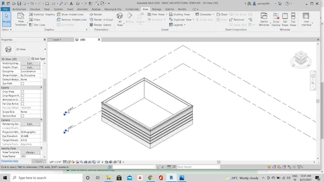
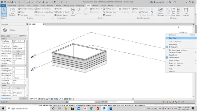
- Place the cursor on the view cube and right click on the view cube.
- The new tab displays and click on the save view option.
- Save the view as a 3d rectangular wall.
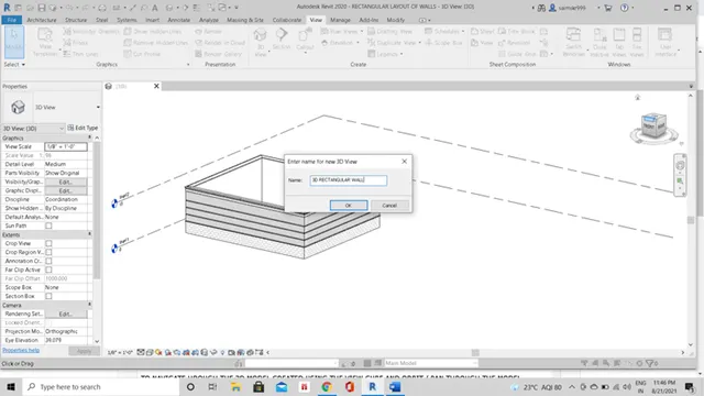
- Click ok.
RESULT:
Therefore, we created a new 3d view and named as a 3d rectangular wall by using the view toolbar.
7)
AIM:
To navigate through the 3d model created using the view cube and orbit / pan through the model.
PROCEDURE:
- Click on the view cube and hold the view cube and rotate the view in all the directions.
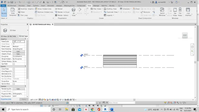
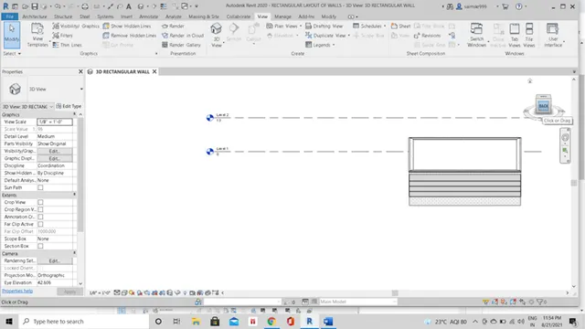
- For the orbit view click on the navigation wheel below the view cube and select the orbit and hold the mouse left button and rotate along all the directions.
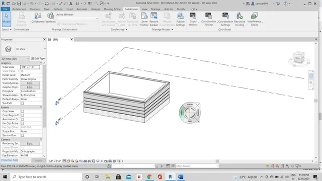
- Scroll and hold the middle wheel of the mouse for the pan.
RESULT:
The created 3d model has been navigated by using the view cube. oribit and pan done by holding the mouse curser.
8)
AIM:
To switch the model to shaded, realistic and hidden lines using the visibility settings.
PROCEDURE:
- Click on the graphic visual style icon available on the toolbar at the bottom of the window.
- By default, our model is in hidden lines, to switch to shaded select the option shaded from the visual style.
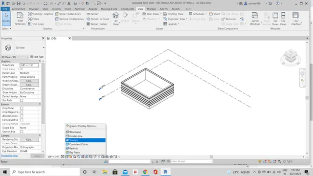
- Similarly for the realistic view select the option as realistic from the visual style icon.
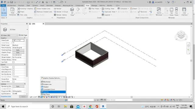
- For the shaded view select the option as shaded view from the visual style icon.
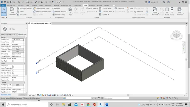
RESULT:
Therefore, the model has been switched to realistic, shaded and hidden lines by using the visible settings.
9)
AIM:
To turn on and off the sunpath to view shadings in the layout created.
PROCEDURE:
- Click on the sun settings from the bottom of the tool bar.
- To turn on the sunpath switch it on from the sun settings.
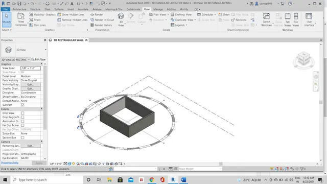
- Similarly, to turn off the sunpath switch it off from the sun settings.
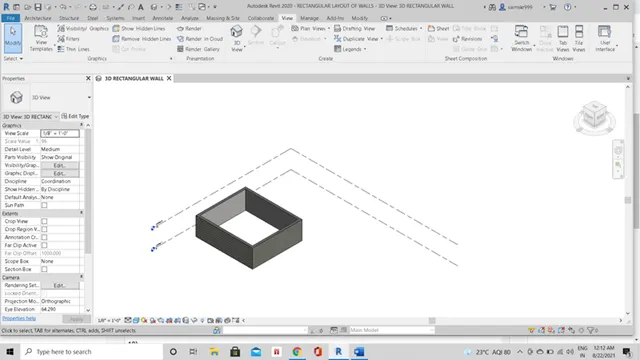
RESULT:
The sun path is turned on and off, which displays the compass, position of the sun and the time of the day, and the time of the year.
10)
AIM:
To use the manage toolbar to enter project settings / project name / project issue date.
PROCEDURE:
- To access to the project information, click on the manage toolbar.
- Click on the project information icon.
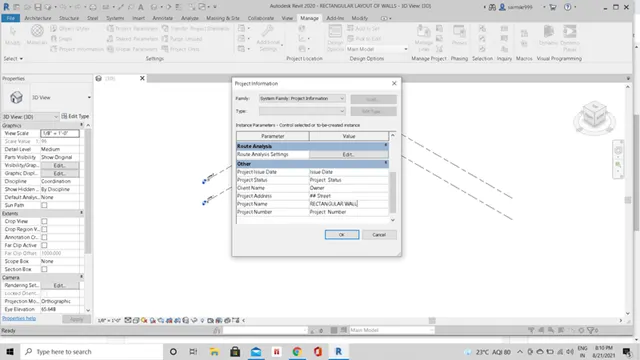
- Enter the project required details suchas project name, issuedate and status.
- Click ok.
RESULT:
The project details have been entered in the project information tab.
11)
ANALYZE TOOLBAR USED IN REVIT AND BENEFICIAL FOR DESIGN AND MODELLING:
The analyze toolbar in the revit is useful to perform the analysis of the structural building. By accesing to the boundary conditions in the analyze toolbar it helps to define the points and boundary area of the analytical model.

We can apply different load combinations to our analytical model to evaluate the performance of the building. We can also combine the different load combinations by using load combination icon.
For design and modelling it provides the different analytical models and the respective elements, and the material to construct the building.
Analyze toolbar also provides the spaces and zones, reports and schedules of the project, check systems to check the model and provides the energy optimisation for the modelled building from the features and the conceptual masses that we are provided and it performs the energy analysis and color fill and the route analysis.
12)
LINKS THAT REVIT SUPPORTS TO BE LINKED TO THE MODEL:
THE VARIOUS LINKS THAT REVIT SUPPORTS TO BE LINKED TO THE EXISTED REVIT MODEL ARE AS FOLLOWS
- LINK REVIT: Allows to link another revit model to existed model.
- LINK CAD: Allows to Link The 2d Cad File to The Existed Revit Model to Create 3d Models by Using the Revit Tools.
- LINK IFC: Revit supports to link the IFC file to the existed revit model to reference its information for the additional work.
- LINK DWF MARKUP: It links the marked up dwf files into the existing revit model so we can see the markups on the corresponding sheets.
- DECAL: Places an image on a surface of building for rendering.
- POINT CLOUD: Links a point cloud file into the current revit project. When linked into project point clouds can provide references when you are placing or editing model elements.
- COORDINATION MODEL: Links a NWD or NWC file to provide context for the revit model. This feature allows we to compare the revit model to a non-revit model for the coordination purposes.
- MANAGE LINKS: Provide options for managing links to building models, cad files, dwf marked up files and point cloud files. From the manage links we can also link cad files and revit models to the current revit project.

13)
COLLABORATE TAB IN REVIT WHICH SUPPORTS MODELING AND ITS EFFICIENCY:
The collaborate tab in revit helps us to colloborate different team members who are working on the same project so that team members can work on the same project simultaneously.
We can link multiple revit models on the same local area network, allowing team members to work on the same project.
To collaborate and work together by the team members who are in the same location can use the revit cloud worksharing.
To collaborate among the team members who are not in the same geographic location can use revit server or revit cloud worksharing.
- Revit servers connects the team who shares the work who are not on the same geographic location.
- Revit cloud worksharing is a cloud-based network ebables us to connect who are within or outside the network to work on the revit project.
