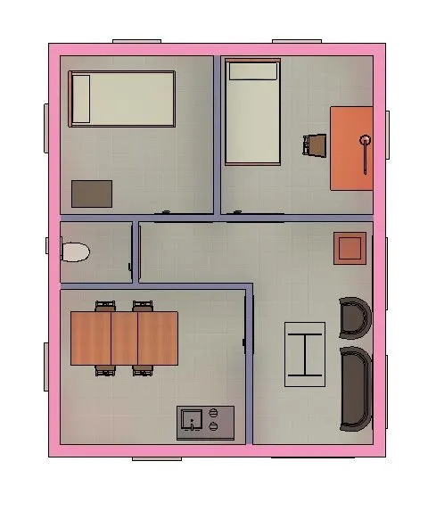
Creating Levels, Grids, Layout and model elements for a residential unit using REVIT
Answer:
1]BIM
-It is acronymn for Building Information Modelling.
-It is a process of creating and managing information for a built asset throughout its lifecycle—from planning and design to construction and operations.
BIM is used for creating and managing data during the design, construction, and operations process. BIM integrates multi-disciplinary data to create detailed digital representations that are managed in an open cloud platform for real-time collaboration.
FEATURES-
-A 3D model enables users to understand relationships between spaces, materials, and various systems within a physical structure. BIM software can be used for every step of the process, from planning to design to construction.
-Easy access to information
-Making the process more expressive
-More comprehensive view of the project.
BENEFITS OF BIM-
- Improve Onsite Collaboration and Communication.BIM allows teams to share project models and coordinate planning, ensuring all designers have insight into the project.
- Model-Based Cost Estimation.BIM automates the time-consuming task of quantifying and applying costs
- Visualize Projects in Preconstruction.3D visualizations allow clients to experience what the space will look like offering the ability to make changes before construction start. Having a greater overview from the beginning minimizes expensive and time-consuming changes later.
- Better Coordination and Clash Detection.You can avoid last-minute changes and unforeseen issues by enabling easy reviewing and commenting across multiple disciplines.
- Mitigate Risk and Reduce Cost.Better overview of the project before starting allows for more prefabrication and reduces waste on unused materials.
- Improved Scheduling/Sequencing.BIM allows design and documentation to be done at the same time, and for documentation to be easily changed to adapt to new information such as site conditions
- Increase Productivity with Prefabrication.By designing, detailing and building offsite in a controlled environment, you can diminish waste, increase efficiency, and reduce labour and material costs.
- Resource Tracking.
Aim-To understand cocept of categories, families, elements, instances and insert in Revit model.
Introduction-In Revit there is inbuilt family which is we will use in our model. It gives better minor detail in model.
Category-A Category controls the organization, visibility, graphical representations, and scheduling options of Families within the Project.
Family-A Family is a grouping of 2D and/or 3D information that serves to represent a discrete building or documentation element in the Project. It defines parametric, graphical, and documentation requirements.
Element-It is a specific representation in a Family defined by distinct parametric, graphical, and documentation characteristics which makes it unique from other Types in the Family.
Instance-An Instance is an individual representation of a Type in the Project defined by unique parametric, graphical, and documentation characteristics which makes it unique from other Instances in the Project.
Procedure-
-Go to Insert tab>Load Autodesk Family>Select Door>Click on door>load it
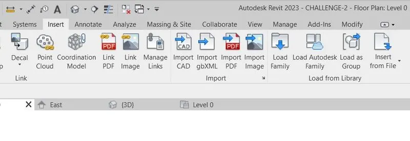
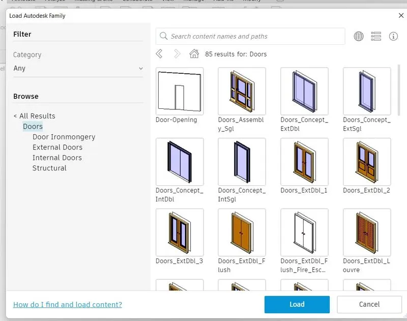
-Now go to Project Browser>Select Family>Select door>Select dimension and drag it in our drawing.
-This is the same procedure follow for other elemnts also.
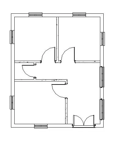
Result-
We understand the concept of Categories, Families, Elements, Instances.
Aim-To open a project with Architectural template, save file with appropriate name, set up project unit, complete project information and set up backup to 3.
Introduction-Start modelling in Revit by follwing this steps:-1)Open a project with template
2)Save file with appropriate name
3)Set up unit by using Manage tab
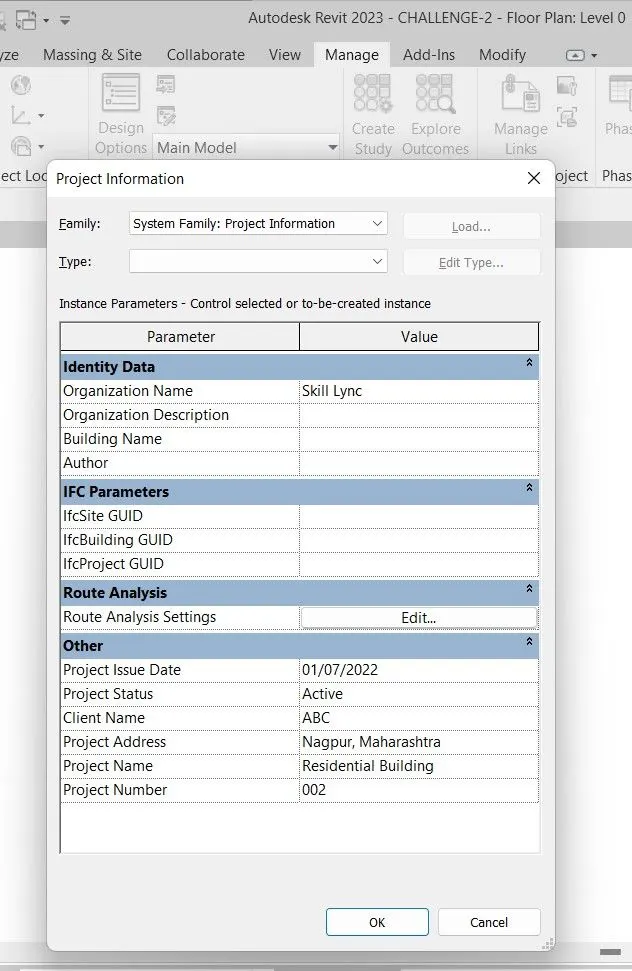
4)In Manage tab complete project information
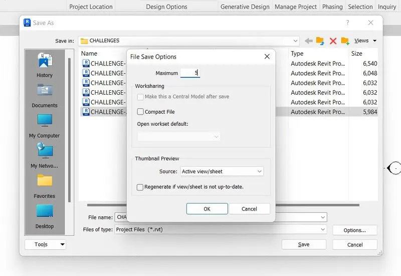
5)Set up backup
In Revit we can store the whole information about project like issue date, type of building, etc.
Procedure-
-Open revit software, following screen shows
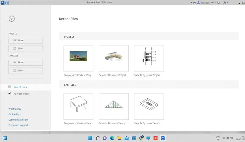
-Then click on New and select template which we want to as well select project
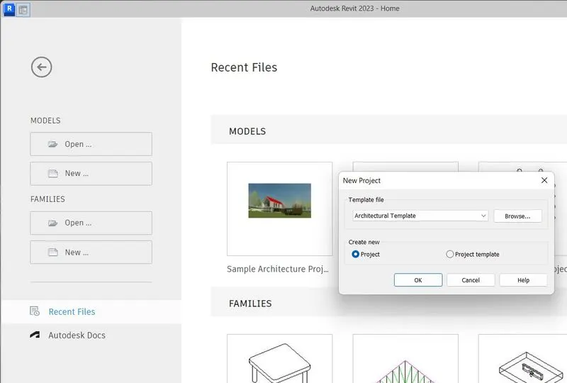
-Now the project file is open
-Go to file menu and save it as a "CHALLENGE-2".
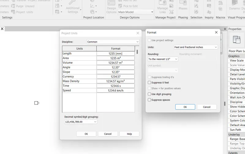
-Now go to Manage Tool>Setting tab>Select project unit>Click on length>change it to feet and fractional inches>Ok.
-Again go to Manage tab>Setting tab>Select Project Information and fill all the details
-Go to Manage tab>Project location
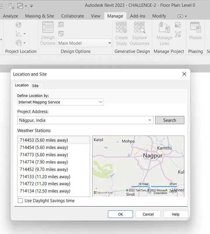
-Now go to file>select Save as>Select Project>Click on Option and save it as backup 3
-Now we can start the drawing
Result-
Project is set up in Architectural template
File is saved with name "Challenge-2"
Unit is also set
Project information also completed
Backup for project to 3 is done.
Aim-To understand the concept of levels and grids.
Introduction-Here i am using the same file which is cretaed in above question
-After setting all unit and information now create the levels and grid. By using levels we can easily set up the building and grid helps for the position of columns and many more.
Procedure-
-Open the file "Challenge-2"
-Go to Project Browser>Select Elevation>Double click on East
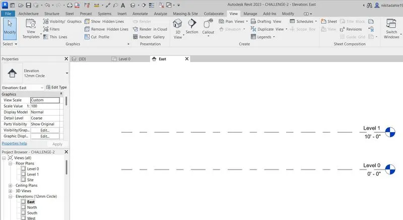
-Now go to Architecture>Datum toolbar>Select Level>Click on Pick lines>Set offset 10'>Select level
-After creating levels, double click on level and rename it as given Ground Floor @ 0'0", First Floor@ 10'0", Second Floor @ 20'0", Roof @ 30'0".
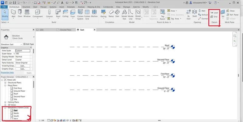
-To create Grid , Go to Project Browser>Seelct Floor plan >Double click on Ground Floor
-Now go to Architecture tab>Datum toolbar>Select Grid>Select line. Draw transverse line then double click on that text and rename it as "A".
-Again go to Architecture tab>Datum toolbar>Select Grid>Select Pickup line>Set offset 10'0">Select grid that we created
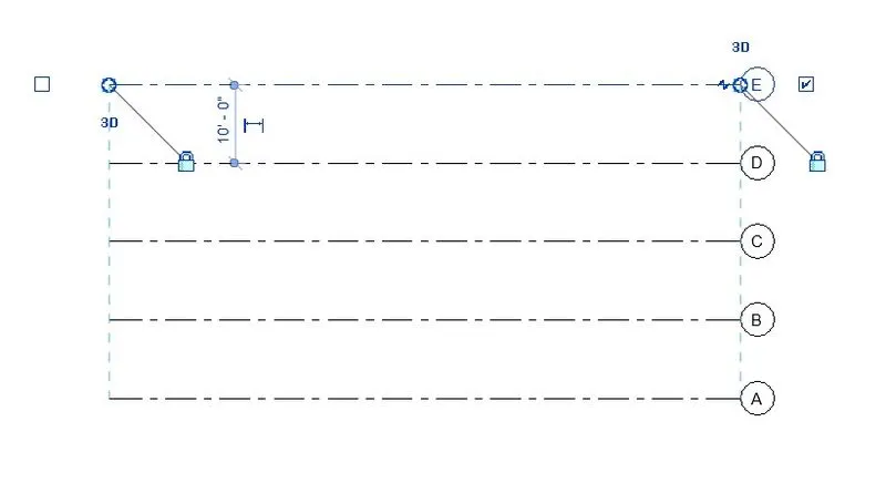
-Now go to Architecture tab>Datum toolbar>Select Grid>Select line. Draw Longitudinal line then double click on that text and rename it as "1".
-Again go to Architecture tab>Datum toolbar>Select Grid>Select Pickup line>Set offset 20'0">Select grid that we created and mark Grids.

Result-
Levels are created.
Grids are created.
Aim-To draw 3D modelling of residential unit.
Introduction-All dimensions are in feet and inches.
Here i am using "Challange-2" file.
Procedure-
-As we created "Challenge-2" file in above where we take Architectural template, set unit in feet and inches, complete all the project details, set backup and location, also levels are created,
-Now in that file go to Architecure toolbar>Select Wall>Select Architecture wall>Go to Propertoes>Select concrete wall>Edit>Make it duplicate as EXTERIOR WALL change thickness to 9" and draw first outer wall
-Again go to Architecure toolbar>Select Wall>Select Architecture wall>Go to Propertoes>Select concrete wall>Edit>Make it duplicate as INTERIOR WALL change thickness to 5" and draw inner wall
A
-To draw floor go to Architecture toolbar>Floor>Select Architectural>Draw by lines>Go to properties>Edit it FLOOR and give thickness 6"
-In Ground floor level to make visible floor go to View>Graphics>Select Visibility>Mark the floor
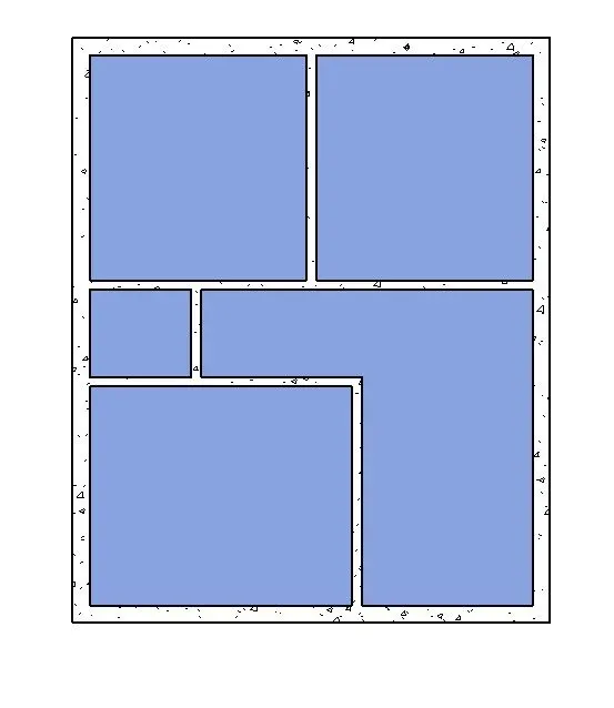
-Now go to Architecture toolbar>Select Area>Area plan>Draw boundary>Tag area by applynig Area
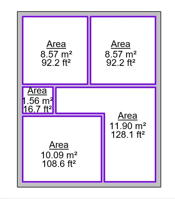
-Similarly we can tag Room in this plan.
-Go to View>Select 3D view
-Now apply material to this structure for that, First select outer wall then go to Properties>Edit>Select structure Edit>Click on material and select material for wall
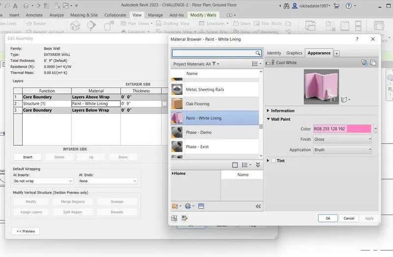
-Follow this same procedure for apply material to inner wall and floor.
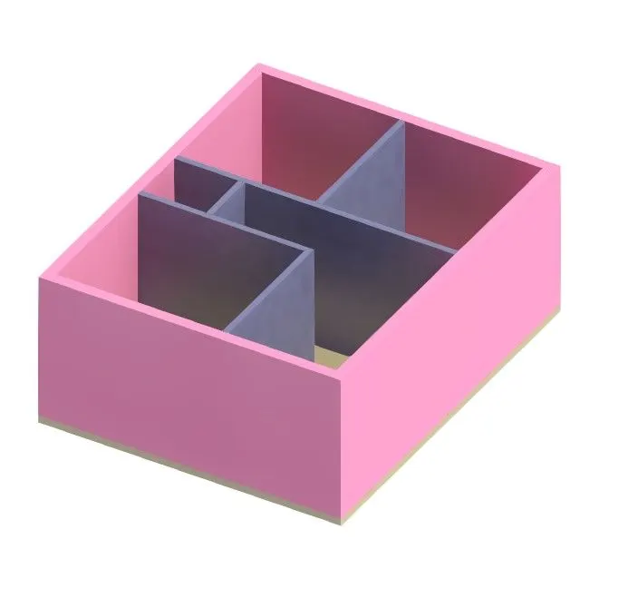
Result-
This is 3D residentail building
Aim-To give dimension to 3D residential unit.
Intodeuction-In above residential model is created. Dimension are in feet and inches.
Procedure-
-As we created the 3D model
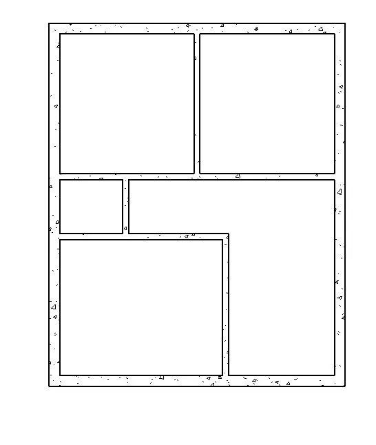
-Go to Annotate>Dimension>select linear
-Go to Annotate>Dimension>select Aligned
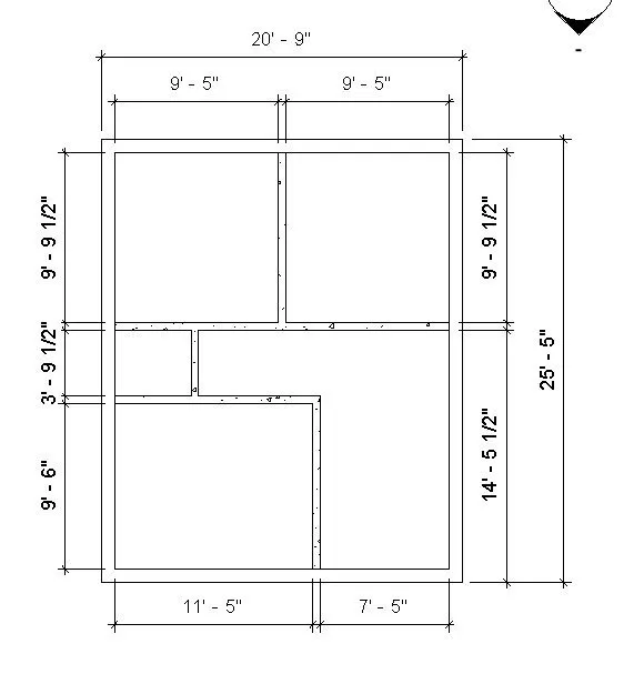
Result-
Dimension provided to each componets
Aim-To provide furniture in redential unit
Introduction-In Revit there is inbuilt family for furniture, and other components related to residential unit.
Here i am using above residential plan
Procedure-
-As we already created residential plan
-Go to Insert tab>Load Autodesk Family>Select Door>Click on door>load it
-Now go to Project Browser>Select Family>Select door>Select dimension and drag it in our drawing.
-Follow this same procedure for other elements like, window, bed, lamp etc.
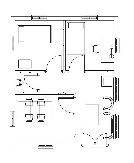
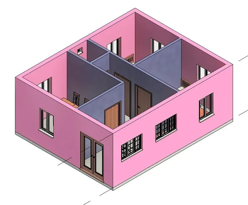
Result-
3D Residential model with door, window, beds etc.