Creation of geometries by Coordinate system methods using AutoCad
Aim-To draw P1 and P2 drawing using all co ordinate system.
Introduction-Here we are drawing a sketch on autocad software with line commamd using all 4 types of co ordinate system.
Procedure-
1.Take imperical template with decimal dimesions
2.Type l in command and a start a drawing
3.Co-ordinates methods are
(i)Absolute co-ordinate method
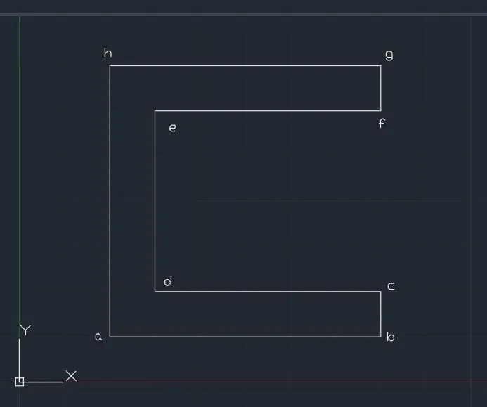
-Specify a point 2,1
-Specify b point 8,1
-Specify c point 8,2
-Specify d point 3,2
-Specify e point 3,7
-Specify f point 8,7
-Specify g point 8,8
-Specify h point 2,8
-Enter c and close the drawing.
(ii)Relative rectangular co-ordinate method
-Specify a point 2,1
-Specify b point @6,0
-Specify c point @0,1
-Specify d point @-5,0
-Specify e point @0,4
-Specify f point @5,0
-Specify g point @0,1
-Specify h point @-6,0
-Enter c and close the drawing.
(iii)Relative polar co-ordinate method
-Specify a point 2,1
-Specify b point @6<0
-Specify c point @1<90
-Specify d point @5<180
-Specify e point @4<90
-Specify f point @5<0
-Specify g point @1<90
-Specify h point @6<180
-Enter c and close the drawing.
(iv)Direct distance entry method
-Specify a point 2,1
-To specify b point move cursor in direction of b entering specific measurement i.e. 6 and repectively for all others point and at last close the drawing by type c.
For P2 drawing:
(i)Absolute co-ordinate method
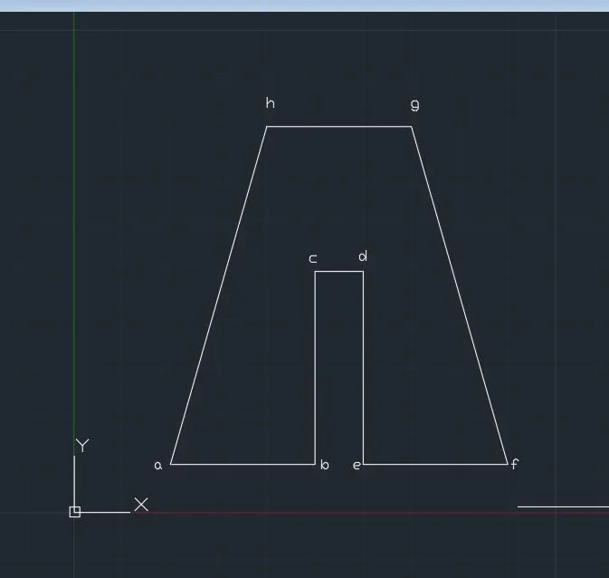
-Specify a point 2,1
-Specify b point 5,1
-Specify c point 5,5
-Specify d point 6,5
-Specify e point 6,1
-Specify f point 9,1
-Specify g point 7,8
-Specify h point 4,8
-Enter c and close the drawing.
(ii)Relative rectangular co-ordinate method
-Specify a point 2,1
-Specify b point @3,0
-Specify c point @0,4
-Specify d point @1,0
-Specify e point @0,-4
-Specify f point @3,0
-Specify g point @-2,7
-Specify h point @-3,0
-Enter c and close the drawing.
(iii)Relative polar co-ordinate method
-Specify a point 2,1
-Specify b point @3<0
-Specify c point @4<90
-Specify d point @1<0
-Specify e point @4<270
-Specify f point @3<0
-Specify g point @7<106
-Specify h point @3<180
-Enter c and close the drawing.
(iv)Direct distance entry method
-To specify b point take a cursor in b direction and type specific value i.e. 3 and respectively for all others point and at last close the drawing by type c.
Result-This is final drawing of P1 and P2.
Aim-To draw profile and trusses by using relative rectangular and polar co-ordinate method.
Introduction-Here we are drawing a sketch on autocad software with line commamd using relative rectangular and polar co-ordinate system.
Procedure-
1.Take imperical template with decimal dimesions
2.Type l in command and a start a drawing
3.Here i am using relative rectangular co-ordinate method
4.
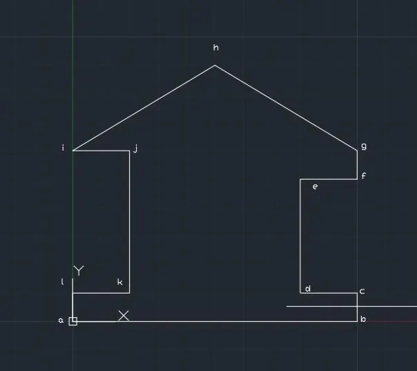
-Specify a point 0,0
-Specify b point @10,0
-Specify c point @0,1
-Specify d point @-2,0
-Specify e point @0,4
-Specify f point @2,0
-Specify g point @0,1
-Specify h point @-5,3
-Specify i point @-5,-3
-Specify j point @2,0
-Specify k point @0,-5
-Specify l point @-2,0
-Enter c and close the drawing.
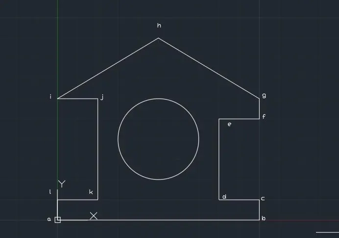
-Then command c enter take a center (5,4) and radius is 2
For 2nd truss diagram-
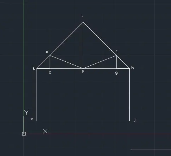
-Specify a point 1,1
-Specify b point @1,4
-Specify c point @1,0
-Specify d point @0,1
-Specify e point @2.536,-1
-Specify f point @-2.536,1
-Specify g point @0,-1
-Specify h point @1,0
-Specify i point @5<135 then from point i @5<225
-From point h simply take cursor in direction of j with value 4.
-At last simply draw a line form point c to e , e to g and e to i.
For 3rd truss-
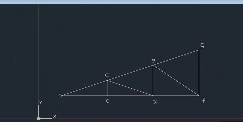
-Specify a point 1,1
-Specify b point @2,0
-Specify c point @0,0.667
-Specify d point @2,-0.667
-Specify e point @0,1.333
-Specify f point @2,-1.333
-Specify g point @0,2
-Type c and close the diagram
-At last draw a line from point b to d and d to f.
Result-This is final diagram