Creating a Floor plan, Footing detail and Isometric view using AutoCad
Aim-To draw a sketch of C.S. of load bearing wall over spread footing by using autocad.
Introduction-Here are we using line, rectangle command and some snap setting. With the help of provided dimensions which will be shown in drawing.
Procedure-
-Take rectangle by rec command of 0.9,0.5
-Now take a line command and start drawing from left end point of rectangle and move a cursor in direction we need to draw a line with specific dimension i.e. Direct dstance entry method
-From that left end point draw a line of 0.2 in horizontal direction and in vertical 0.4 then towards right 0.05 again in vertical direction 0.4 and towards left 1.15 then in downward 0.30 and draw st perpendicular line.
-By snap setting, on snap mode with perpendicular point, end point, mid point and center.
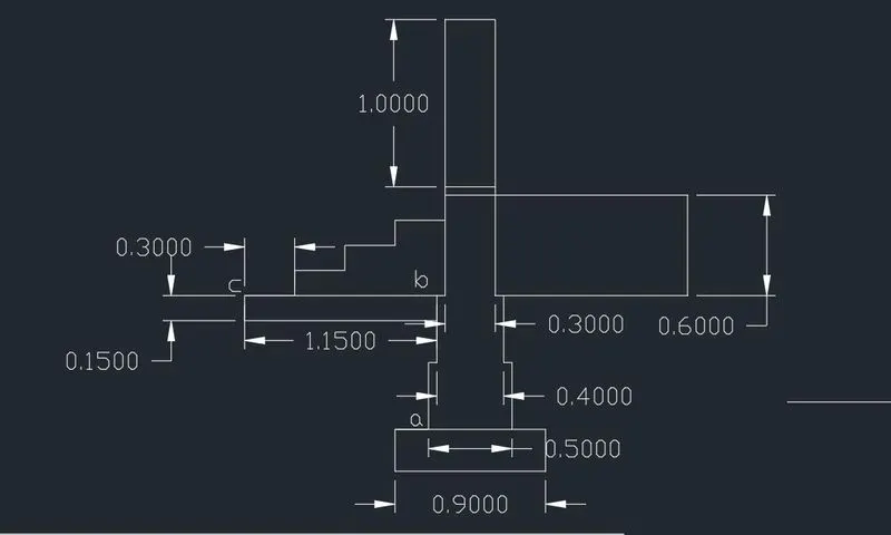
-Now from point b draw a line towards right 0.05, upward 0.6, again 0.05, again 1.0, then towards 0.3, downward 1, again 0.05 then towards right 1.15, downward 0.6 , towards left 1.15.
-From point a to b we can take mirror command to draw in right side so, select lines that we have to mirror and then type mirror take mid point of rectangle and here we have our drawing.
-From point c take line command towards right 0.3, upward 0.15, repeat it till we have 3 steps.
-At last complete sketch by drawing remaining lines.
Result-Final sketch is this
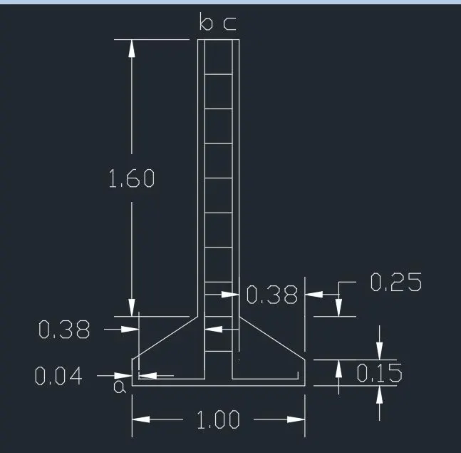
Aim-To draw a sketch of C.S. isolated footing by using autocad
Introduction-The drawing is symmetrical at center.
Procedure-
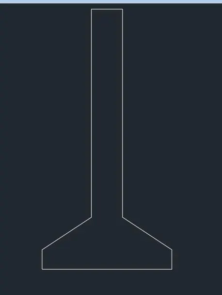
-First we are going to draw is outer drawing of footing.
-Take line command and start the drawing, click anywhere and take a 1st point then towards right it is 1.00, upward 0.15, now @-0.38,0.25 (by using relative co-ordinate relative method) and upward is 1.60.
-Select the lines which is on right hand side and take mirror command mi enter with mid point of line and at last draw a line at upper side of footing.
-
-From point a take a line command @0.04,0.04, from that point upward is 0.04 again from that point towards right 0.38 and vertically perpendicular to the final line.
-Now select recently draw lines and take mirror command so we get symmetrical drawing by joining the point b and c take offset command o enter of 0.20 towards downward continuously 9 times.
-Erase unwanted lines by e enter.
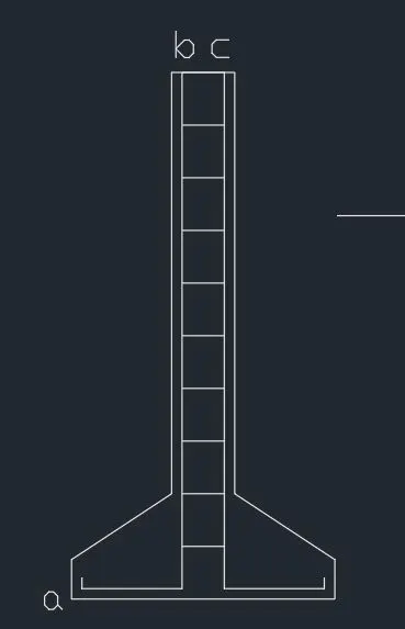
Result-This is final sketch of C.S. of isolated footing with dimensions.
Aim-To draw a line diagram of two bedroom building by using autocad.
Procedure-
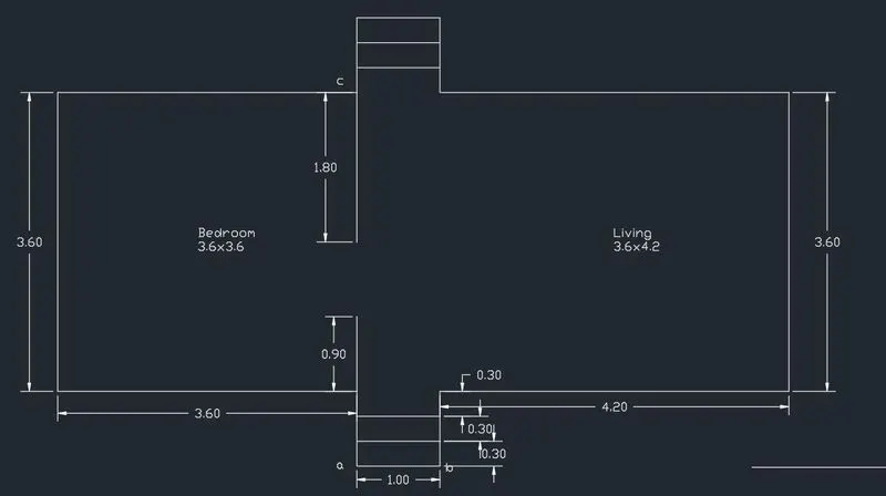
-Take a line command click anywhere and take 1st point then towards right 3.6, upward is 0.9 and from that same point downward is 0.9 then towards right 1 again upward 0.9, towards right 4.2, upward 3.6.
-From start point also upward is 3.6.
-Now select line ab take offset of 0.3 two times.
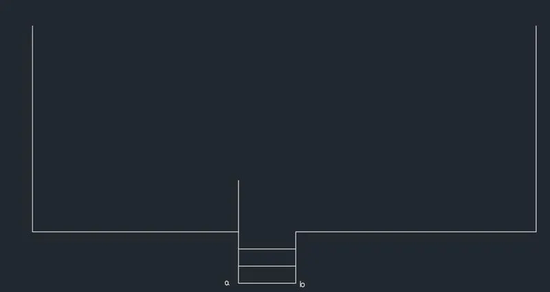
-Select steps and horizontal lines take a mirror command and take mid point of vertical line.
-From point c draw a line downwards 1.80.
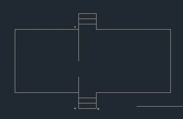
Result-This is final sketch of two bedroom of building i.e. bedroom and living room.
Aim-To draw a C.S. of load bearing wall showing foundation details by using autocad.
Procedure-
-Take a line command take 1st point anywhere and start drawing towards right 0.9, upward 0.45, towards left 0.15, upward 0.40, left 0.05, upward 0.30, left 0.05, again upward 0.60, towards left 0.05, again upward 1.0.
-Now select all lines except horizontal one and take mirror command with mid point
-At last join the lines.
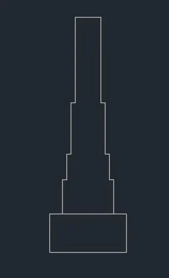
Result-This is final sketch of C.S. of load bearing wall with foundation details.
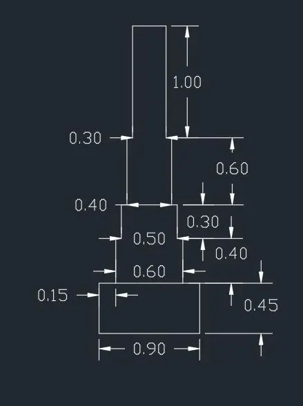
Aim-To draw a isometric view of steps by using autocad,
Introduction-Here we are draw a steps in isometric view.
Procedure-
-First set the isometric view by F5 or by selecting the iso symbol present in autocad besides of command line below.
-Now take a line command and take 1st point anywhere and start the drawing
-Take isoplane left 1.0, upward 0.15, take isoplane right 0.3 again left isoplane 1.0, now take isoplane right 0.3 and join line
-Now select this complete step and take a copy command and put it on point b respectively for other steps also same.
-From point a draw line in isoplane right 0.3 and join the line.
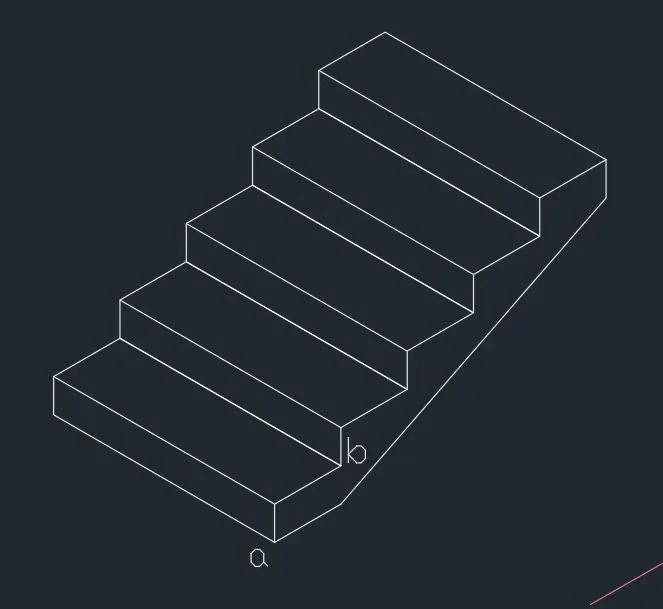
Result-This is isometric view of steps.
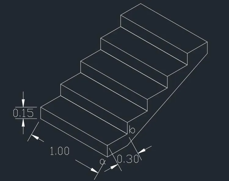
Aim-To draw a isometric view of gable wall by using autocad.
Introduction-We are drawing gable wall in isometric view.
Procedure-
-First set the isometric view by F5 or by selecting the iso symbol present in autocad besides of command line below.
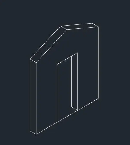
-Start with isoplane right 1, upward 2.42, towards right 1, downward 2.42 again towards right 1 and up 3.