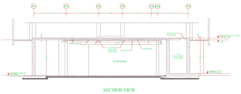
Creating Kitchen layout, Hatching of Architectural elements and sectional view of an Industrial Building in AutoCad
KITCHEN LAYOUT
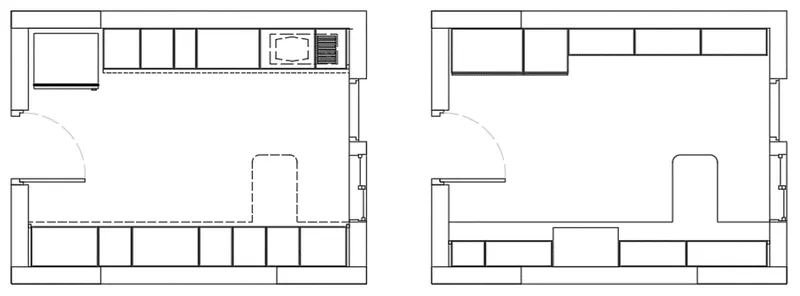
Aim: To draw the Kitchen layout as shown in the Figure above. After sketching and to provide the dimensions and text with the use of layers.
Introduction:
The Kitchen layout drawing is created in AutoCAD using the draw tools and after sketching, the dimensions and text are provided with the use of Layers. The procedure of drawing is explained and the final result is given.
Commands Used:
Units
Limits
Line
Polyline
Circle
Arc
Rectangle
Trim
Extend
Offset
Mirror
Rectangular Array
Hatch
Move
Rotate
Dimlinear
Dimstyle
Fillet
Linetype
Lineweight
Layers
Mtext
Multileader
Procedure:
Step 1
Type unit or UN in the command line and press enter
Set type of unit as decimal and precision as 0
In insertion scale set unit as millimeter.
Step 2
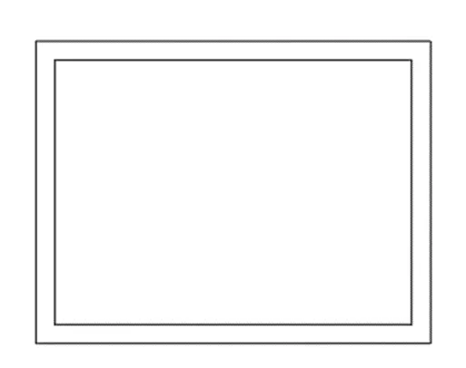
Type REC in the command line then press enter to invoke rectangle tool
Specify the first point on the screen
Type D and Press Enter to specify dimension of rectangle
Specify first length of 4760 then Enter
Specify rectangle second length 3660
Offset 230mm inward to create wall
Step 4
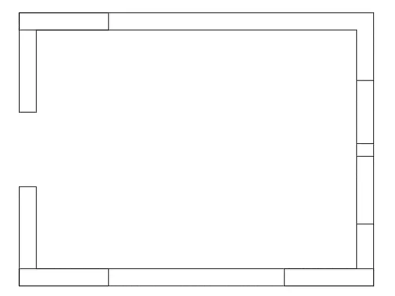
Provide door and window openings
Trim the extra lines
Create columns 1200 x 230 using rectangle
Step 5
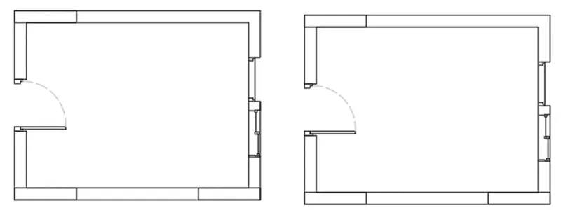
Create doors and windows
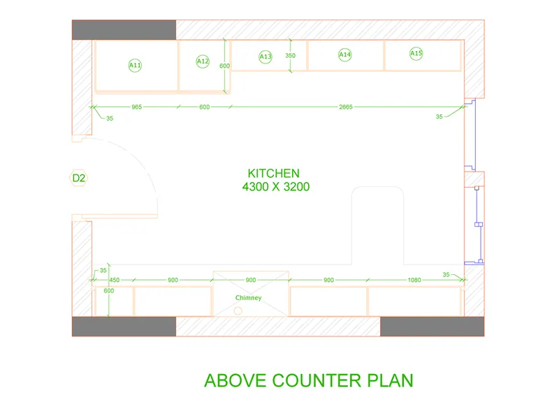
Use copy, select all and replicate to create above counter plan
Step 6
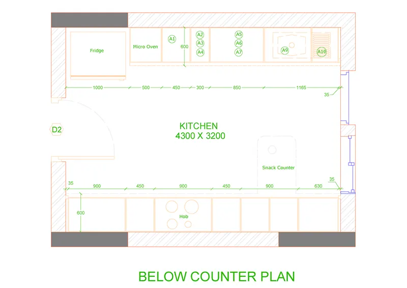
Offset the line using offset command for the respective lengths to create the components, including the fridge.
Afterwards we draw the fridge separately with other dimensions in the kitchen layout.
Draw the line opposite side to create the parts of kitchen.
Next divide the seven parts down side with different dimensions compared to the upper side portion.
Create the all components in both the plans to complete the kitchen layout
Step 7
Hatch walls and columns
Use mtext to label and to indicate the components
Use dimension command and provide the necessary dimensions complete the kitchen layout
Assign the Layers for the respective elements
RESULT
ELEVATION
Aim: To draw the elevation view in AutoCAD using the draw, modify tools with proper dimension techniques and dimension styles to the project.
Introduction:
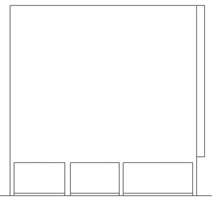
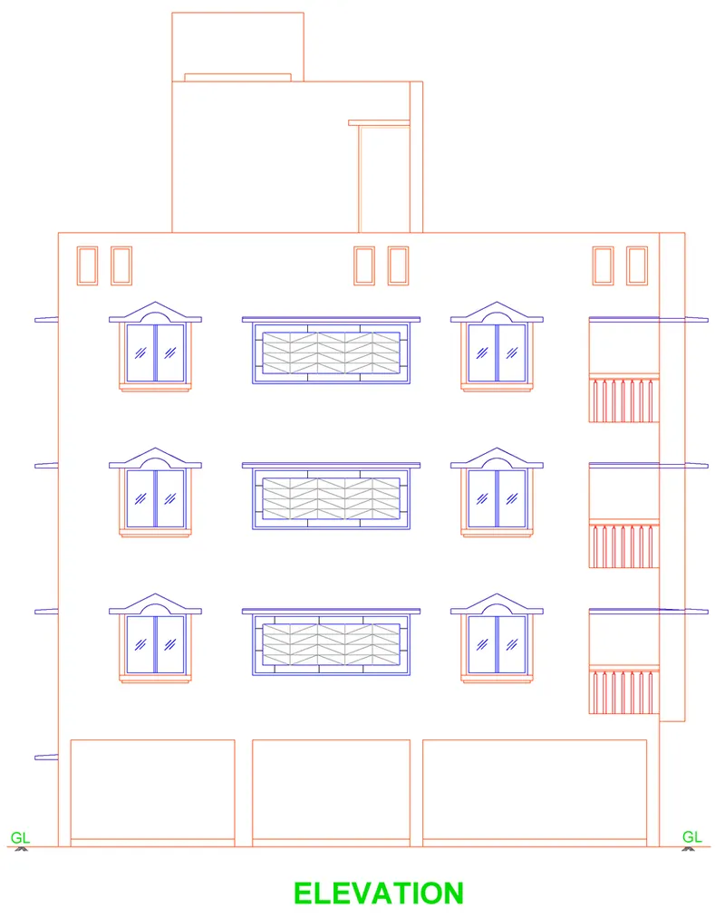
The Elevation is created in AutoCAD using XLine and line tool, the dimensions and text are provided with the use of layers. The procedure of drawing is explained and the final results are given.
Commands Used:
Units
Limits
Line
Polyline
Circle
Arc
Rectangle
Trim
Extend
Offset
Mirror
Rectangular Array
Hatch
Move
Rotate
Dimlinear
Dimstyle
Fillet
Linetype
Lineweight
Layers
Mtext
Multileader
Procedure:
Step 1
Type unit or UN in the command line and press enter
Set type of unit as decimal and precision as 0
In insertion scale set unit as millimeter.
Set upper limit and lower limit of the drawing
Step 2
Draw the construction line from front face of the plan
Draw outer boundaries and mark the columns from the projection line
Offset 150mm from the ground level.
Offset 2085 from ground floor
Offset 2450 from ground floor to create the first-floor level
Offset 12000 from ground floor to create the top-floor level
Step 3
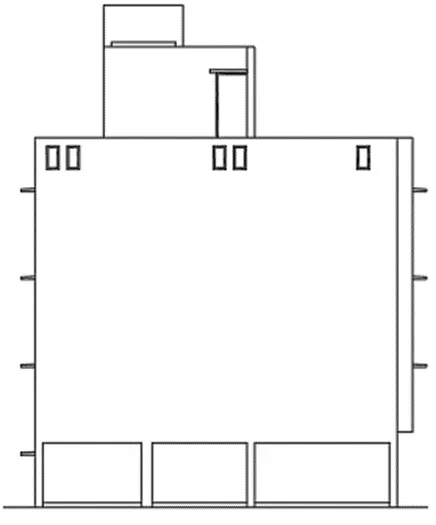
Draw head room by projecting construction line from the plan
Draw door and overhead tank
Draw chejja for windows at every floor
Use rectangle to provide opening for parapet wall
Step 4
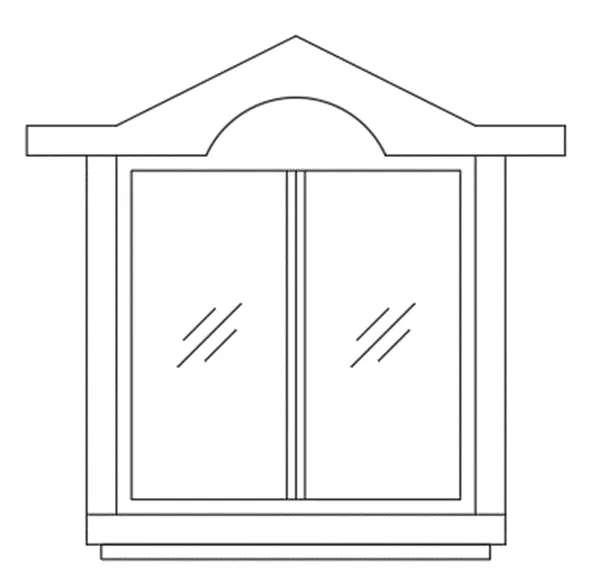
Draw a rectangle of dimensions 1200 x 1500 to create window
Provide chejja at top as shown in figure and draw projection wall to window boundary
Draw window and hatch it
Step 5
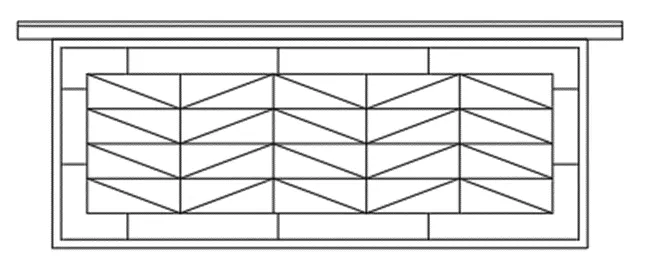
Draw a rectangle of dimensions 3075 x 1200 to create veranda opening
Provide chejja at top as shown in figure and draw projection wall to window boundary
Hatch the boundary and inside the window
Step 6
Provide windows by pasting both the windows to each floor at lintel level
Assign the layer properties
Use mtext to provide text
RESULT
SECTION VIEW OF INDUSTRIAL BUILDING
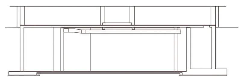
Aim: To draw the section view of industrial building as shown in the Figure above. After sketching and to provide the dimensions and text with the use of layers.
Introduction:
The section view of industrial building drawing is created in AutoCAD using the draw tools and after sketching, the dimensions and text are provided with the use of Layers. The procedure of drawing is explained and the final result is given.
Commands Used:
Units
Limits
Line
Polyline
Circle
Arc
Rectangle
Trim
Extend
Offset
Mirror
Rectangular Array
Hatch
Move
Rotate
Dimlinear
Dimstyle
Fillet
Linetype
Lineweight
Layers
Mtext
Multileader
Procedure:
Step 1
Type unit or UN in the command line and press enter
Set type of unit as decimal and precision as 0
In insertion scale set unit as millimeter.
Step 2
Draw the X-line at any point on the screen.
Next offset the line to top to a distance of 5850mm and we have to do offset of last offset line to the distance of 300mm to the top.
Next, we have to draw the vertical X-line on any point on the horizontal line.
Next do offset of line to right to a distance of 5319mm
Next do offset of line to right to a distance of 5316mm
Next offset the last line with a distance of 3900mm to the right.
Next offset the line with the distance of 4720mm to the right side.
Next offset the line with the distance of 1020mm to the right side.
Next, we do the offset for last line with the distance of 5025 to the right side.
Offset the left and right edges with the distance of 500mm.
Next, we have to trim the outer edges using the trim command
Next offset the bottom edge of the top floor to a distance of 300mm
Next offset the last line with the distance of 100mm to the bottom.
Next, we draw the sprinkler pipe along with the duct pipe.
The duct pipe thickness is 300mm and the thickness of sprinkler pipe is 100mm.
Next, we draw the manhole cover with the thickness of 750mm at the right top edge of filter feed walls as shown in the figure.
Next, we draw the thickness of pump room slab with the different layers using the line command.
Step 3
Assign the layers for the respective elements
Provide dimensions for the given Section AA using the dimlinear command.
Using hatch command, dimension command and text command complete the drawing
RESULT