Creating Bar Bending schedule, Different Door types, and Creation of standard drawing templates using AutoCad
1. Create the templates as shown in Figures. Take the size of the title block as per industry standards or you can assume it as per the size of the paper. Use text and attributes wherever required. After creating the title block you need to save it as a block with names: Custom1_titleblock and Custom2_titleblock, respectively.
AIM:
To create a template block as per the industrial standards using AutoCAD.
PROCEDURE:
Custom1 Title block:
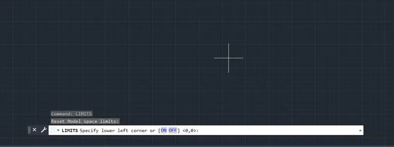
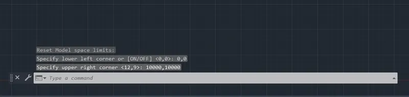
- Set the limits as per the requirements
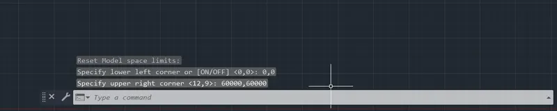
- Specify the lower left corner: 0,0
- Specify the upper right corner: 60000,60000
- Then by using the rec command create a rectangle as per the required partition.
- Using the offset command create the partitions.
- After that by using Mtext command give proper specifications as per the given drawing.
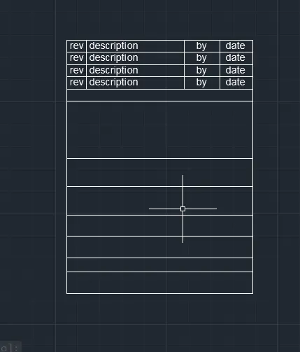
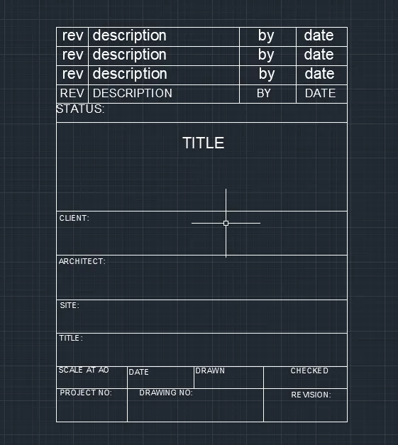
- Using the layer command differentiate the layers using different color.
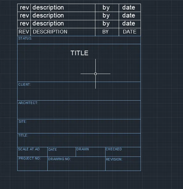
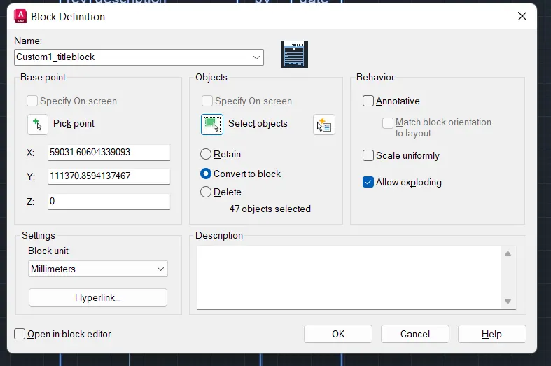
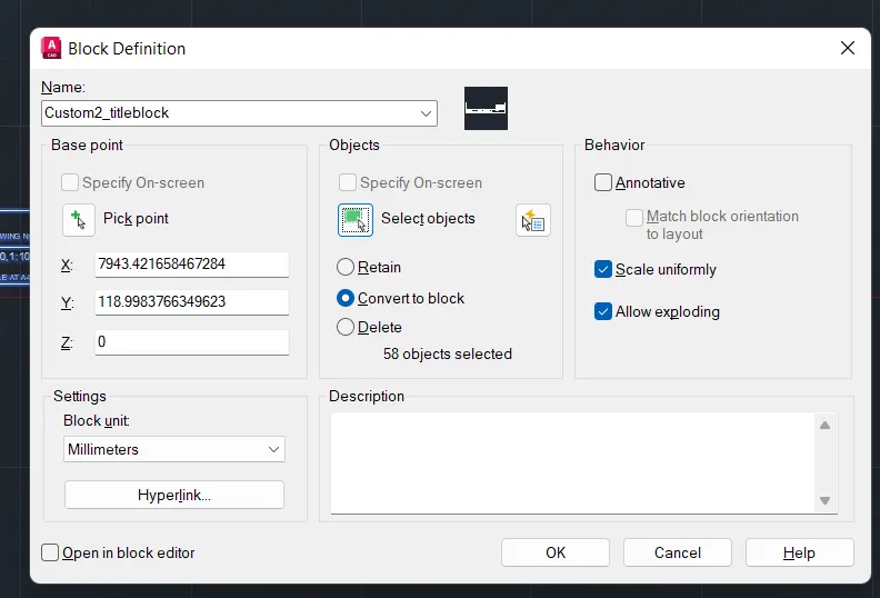
- After completion by using the BLOCK command choose the pick point and then choose the object then enter ok.
- Give block name as per the requirement.
CUSTOM 2 TITLE BLOCK:
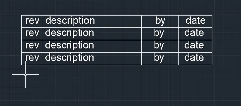
- Again choose line command to draw the table.
- Using the mtext command draft the texts.
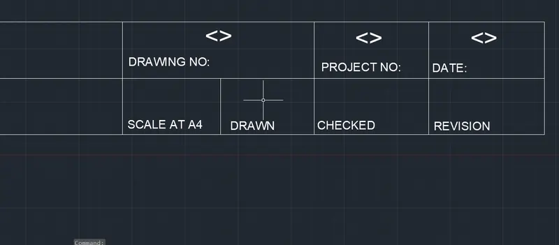

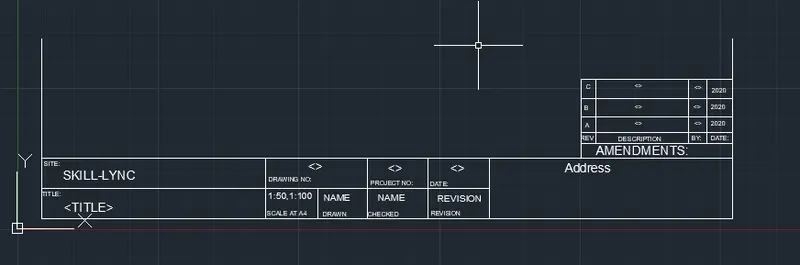
- Now, the next step is to convert it into block.
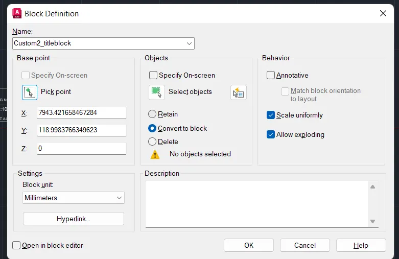
- Then click ok and it is converted into a block.
2. Create the doors type for warehouse as shown in the Figure. You need to create each door type as per standard size or given dimensions. Create the blocks of this door type after creating them.
AIM:
To create the door types for warehouse and to convert the same into blocks.
Procedure:
- Initially set the units of the drawing as decimal (millimeters).
- Now, set the limits of the drawing
- Specify the lower left corner: (0,0)
- Specify the upper right corner: (10000,10000)

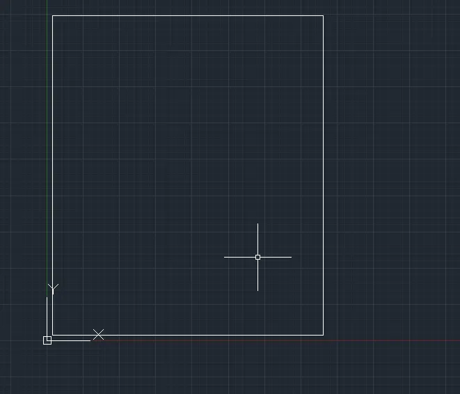
- Draw a rectangle using the command rec having dimension 2330mmx2750mm.
- Now, using the line and offset command draw the panels of the door
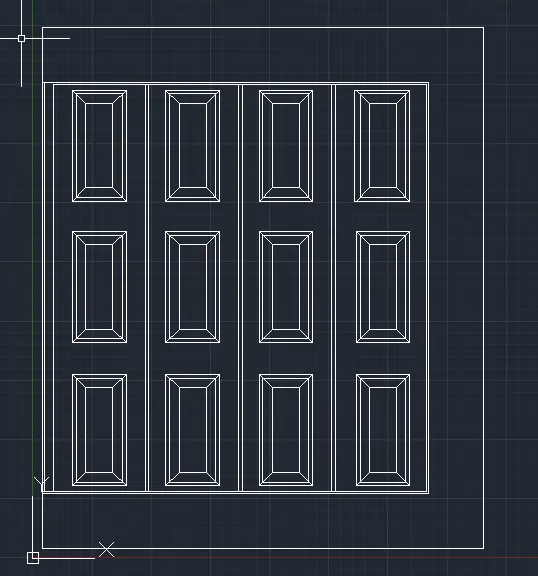
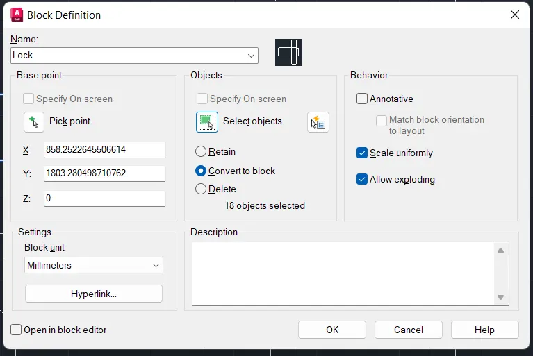
- Now, we have to create the lock for the door, which created separately.
- This can be created using rectancle and fillet command.
- Then convert it to a block.
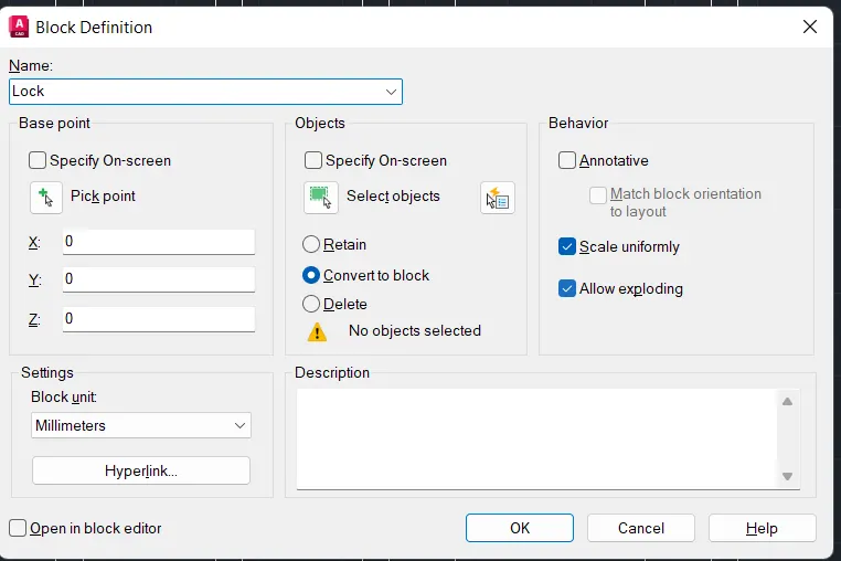
- Now, place this lock on door at appropriate position.
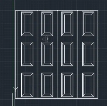
Door 2:
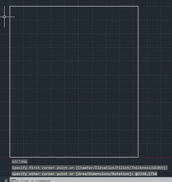
- Draw a rectangle using the command rec having dimension 2330mmx2750mm.
- Now, using the line and offset command complete the door.
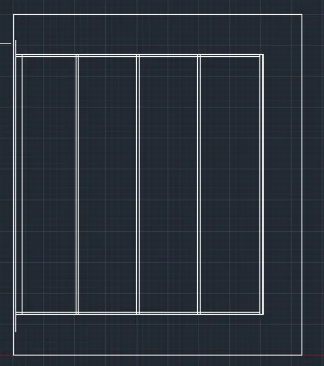
- Now, place the lock that is previously created in the current drawing by insert block option.
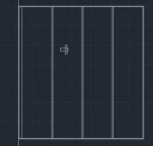
- Now provide the dimensons and text to complete the drawing.
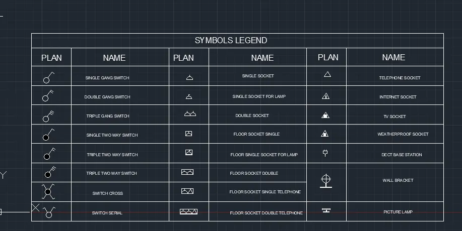
3. Create each symbol as a block with the name given in the legend. After creating the blocks arrange them in the legend as shown in the Figure.
Aim:
To create a symbol legend with each symbol as a block with the name .
Procedure:
- Initially set the units of the drawing as decimal (millimeters).
- Now, set the limits of the drawing
- Specify the lower left corner: (0,0)
- Specify the upper right corner: (5000,5000)
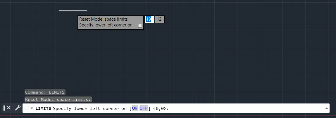

- Inorder to create a symbol legend, first of all create all the symbols individually and then convert them into blocks.
- Now, first one is single gang switch, so for that type c to draw a circle, type L to draw line.
- After drawing convert it into a block.
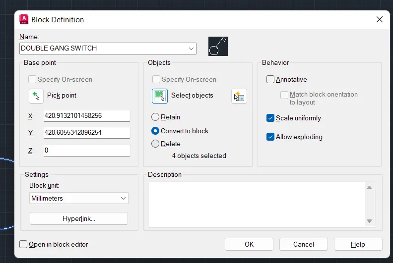
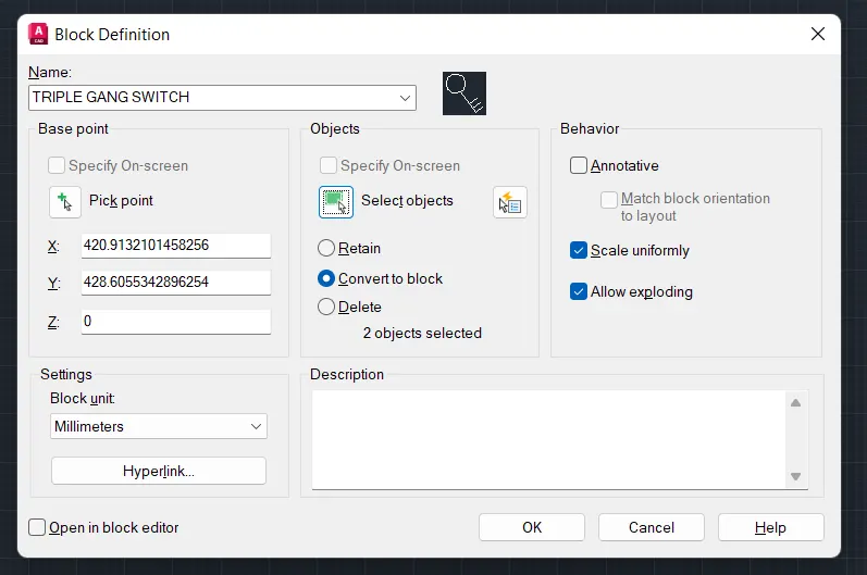
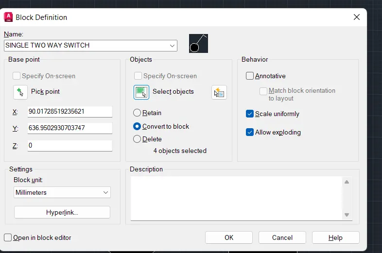
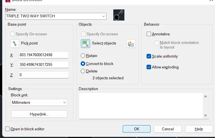
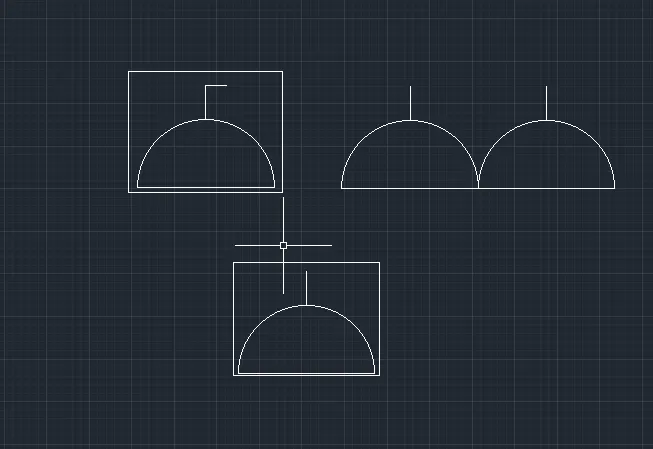
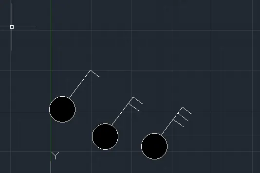
- Hence it is converted to a block.
- Similarly convert all the symbols into bocks after drafting.
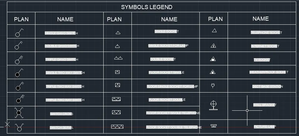
- Now, these symbols has to be inserted into a table along with their names.
- Inorder to draw a table use line command and complete the table.
- Then insert the blocks and their names into the table.
- Names can be inserted from the field option in insert tab
4. Create the door type for residential building as a block. Save the name of the blocks as type. Use given dimensions or assume dimensions as per industry standards.
Aim:
To create the door types for resisdential building as a block.
Procedure:
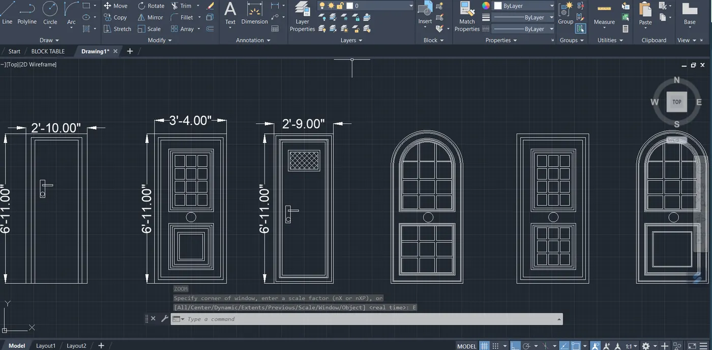
- Initially set the units of the drawing as Architectural (feet and inches).
- Now, set the limits of the drawing
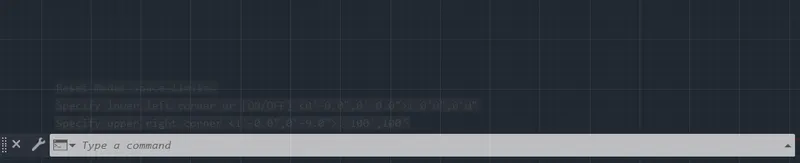
- Specify the lower left corner: (0,0)
- Specify the upper right corner: (100',100').
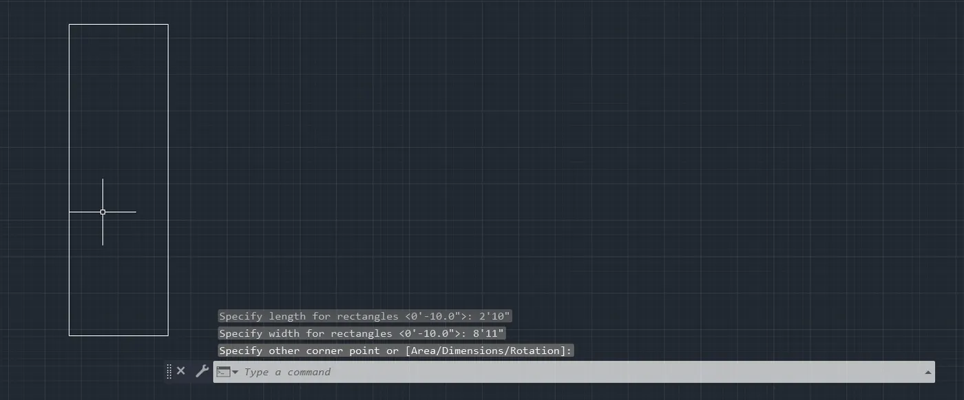
- Using rec command draw a rectangle.

- Specify length for rectangle :2'10"
- Specify width for rectangle: 8'11"
- By using offset command draw the offsets as per the requirements.

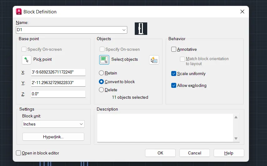
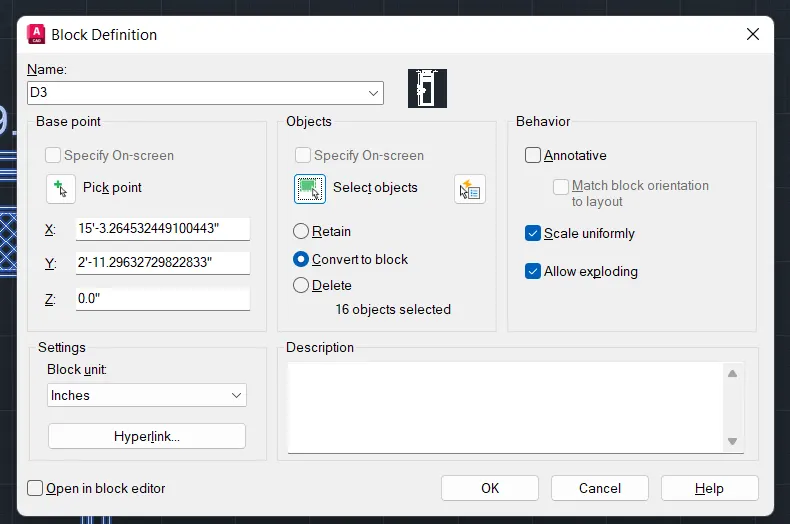
- Now, convert this door to block named Door D1.
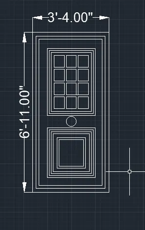
- Again choose line command and draw the out line of the door.
- Then using the offset command draw the panels of the door.
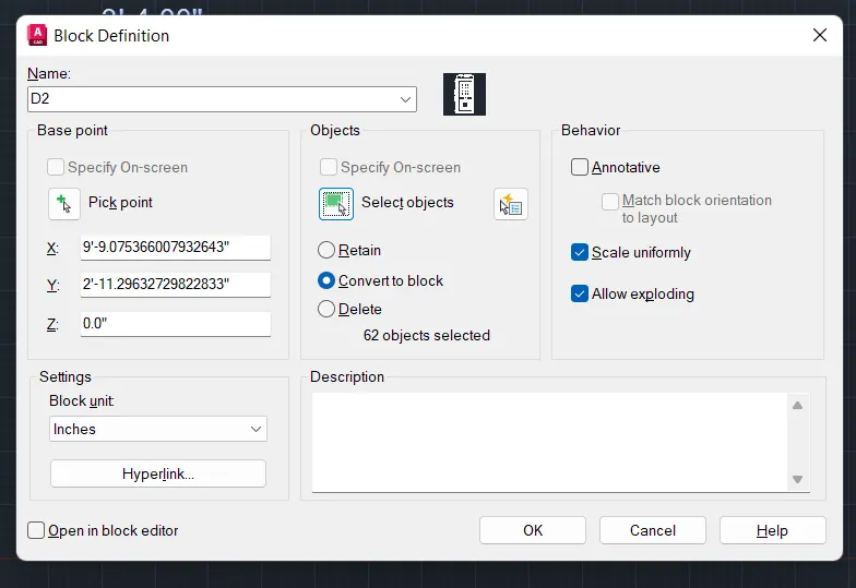
- Now, we have to convert the door so created into block and is named as D2.
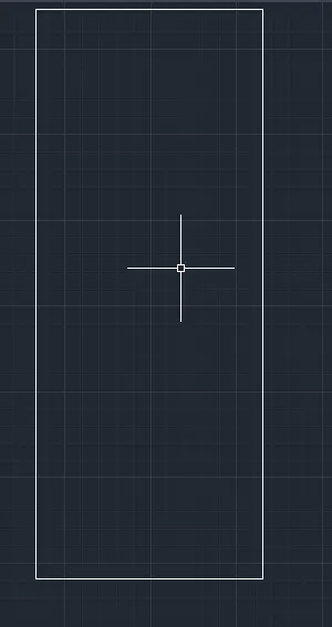
- Using line command draw the outline of the door.
- Within the center portion of the rectangle hatching is provided.
- Using hatch command hatch the pattern required in the door opening
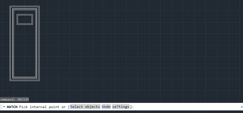
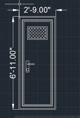
- Now, convert the door so created to block.
- Initially, choose line command an draw an outline of door.
- Then choose arc and make the top portion of the door curved.
- Then using the offset command complete the panels of the door.

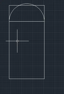
- Trim the bottom unwanted lines.
- Now, provide the dimensions and texts .

- Convert the above door to block
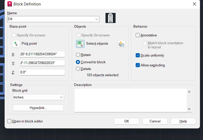
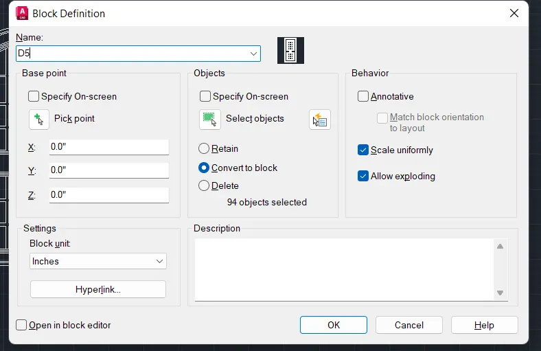
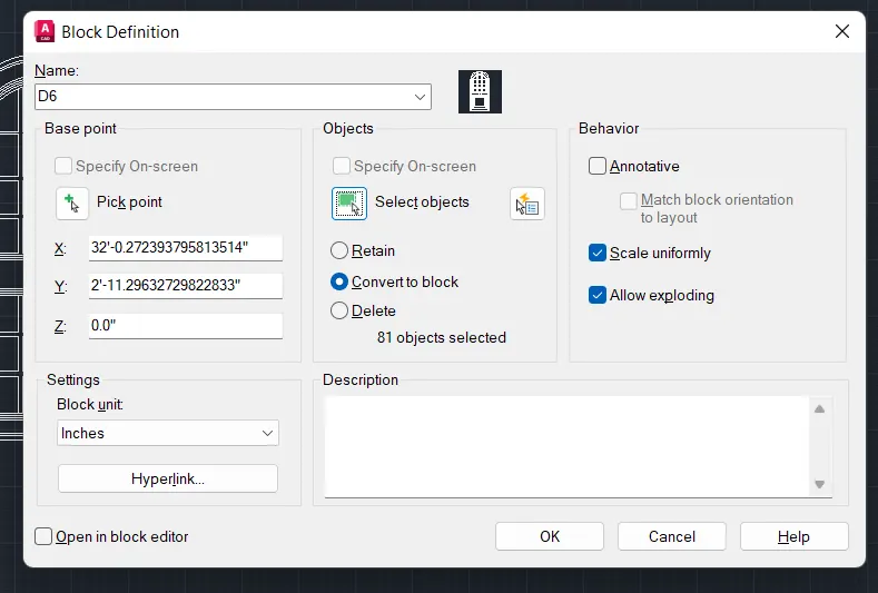
- Hence, all the doors have been created as blocks.
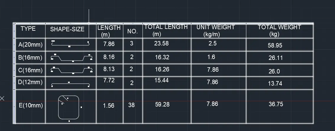
5. Create each shape as a block as shown in the Figure. Save the block and insert them on the table as shown in the Figure.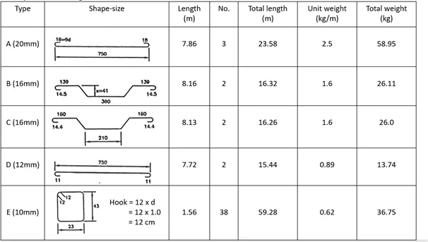
Aim:
To create each shape as a block as shown in the figure and insert these blocks into the table.
Procedure:
- Initially set the units of the drawing as Decimal (meters).
- Now, set the limits of the drawing
- Specify the lower left corner: (0,0)
- Specify the upper right corner: (1000,1000).

- Choose a line command to draw different types of reinforcements in the bar bending schedule.
- Fillet command can also be used to draw the curves.
- Initially create individual shapes and then after providing the necessary dimensions, convert them into blocks.
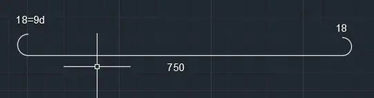
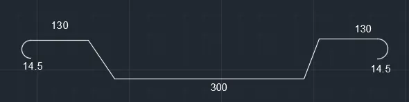
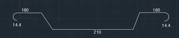
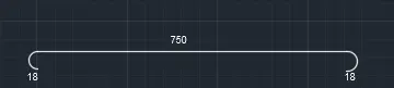
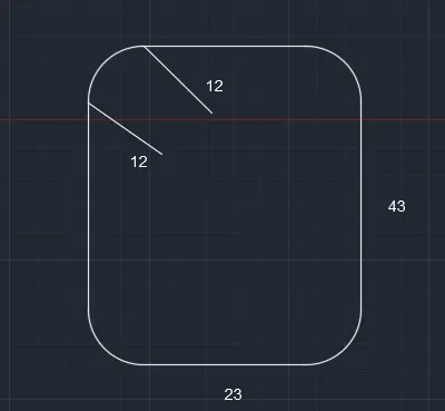
- Then place these blocks into the table so created after appropriate scaling.