Creation of Multiple viewports, Scaling the drawing and setting in Template in AutoCad
Introduction
AutoCAD has two types of viewports: Model space viewport and layout space viewport.
In large or complex drawings, displaying different views reduces the time needed to zoom or pan in a single view. this viewport can be configured from the view tab on the ribbon.
There are different model space viewports configurations like single, two: vertical, two: horizontal, etc. These configurations can be saved and restored by name with the VPORTS command or by pulling down the viewport configuration from the ribbon.
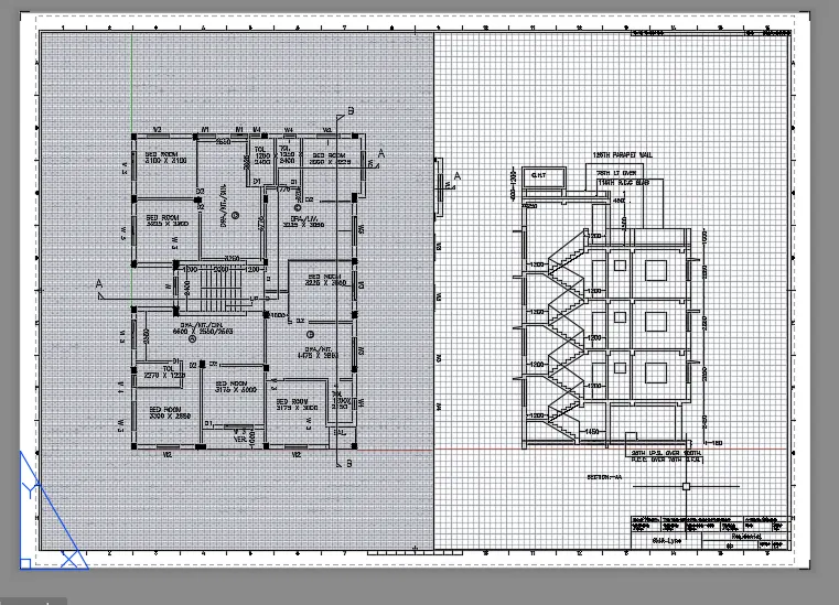
1. Create a layout of the Plan and Section A of the project in Challenges 7, using the template Tutorial-mArch.dwt in a scale as given in the Figure. Use the MV command to create the viewport of the size as shown in Figure. Also, use ATTEDIT command to edit the information in the title block. Use A1 size for the layout. Take a plot.
Aim:
To create the plan layout and section A of challenge 7, using the template Tutorial-mArch.dwt. Use the Mv command to create the viewport. Use ATTTEDIT to edit the information in the title block. Use A11 for the layout and take a plot.
Procedure:
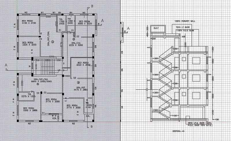
- To create the viewport, initially take the 7th-week challenge that is already made, and from that keep the plan and section A.
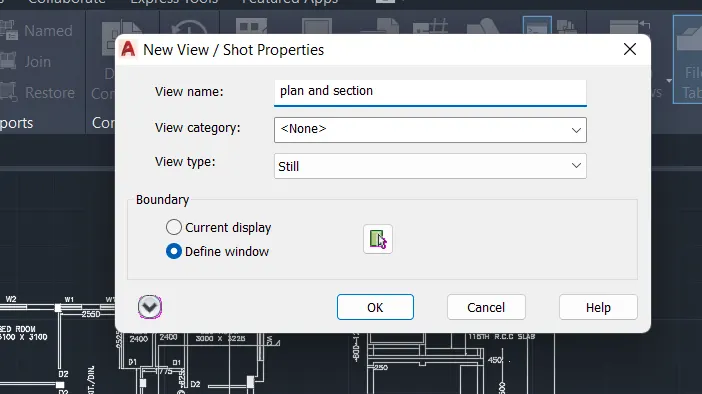
- Now, in the command prompt type V to create the model view of the plan and section.
- Then provide the view name and choose the boundary option.
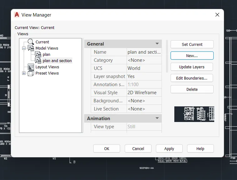
- Using the layout command, choose the required layout.

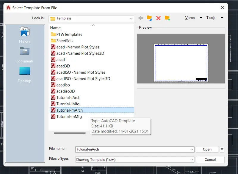
- Now, use the command MV to create multiple viewports and create the viewports as given in the question.
- Then type ms in command prompt to zoom in and out the views in the viewport and PS command to return back to paper space where zooming in and out is not possible
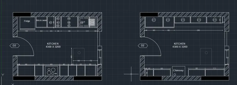
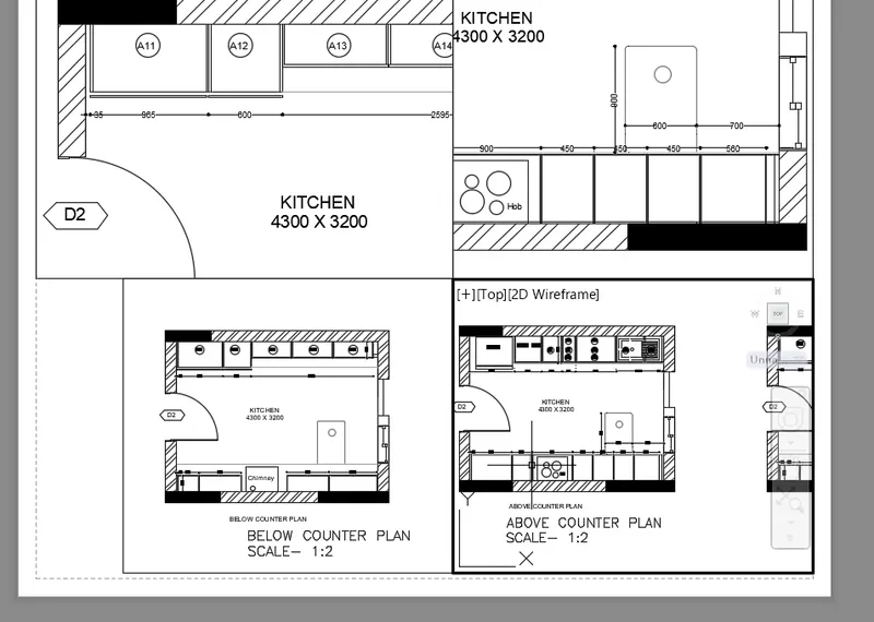
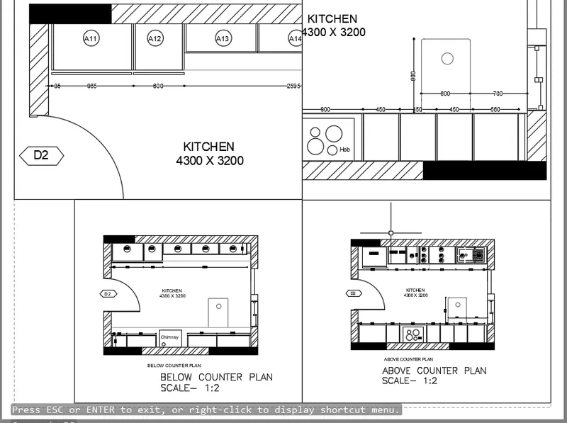
2. Create a layout of the Kitchen drawn in Challenge 9 as shown in Figure. Use the scale as shown in the Figure. Use A4 Size page for the layout. Take a plot.
Aim:
To create the layout of the kitchen drawn in challenge 9 and use an A4 size page for the layout and take a plot.
Procedure:
- To create the viewport, initially take the 9th-week challenge that is already created.
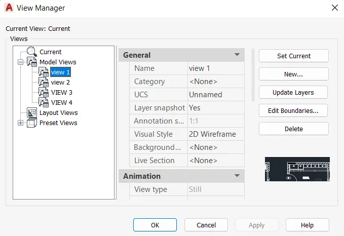
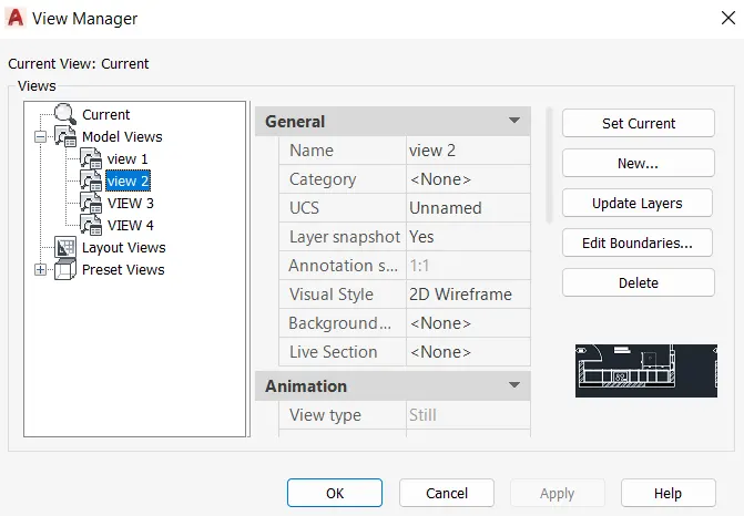
- Now, click ok then apply and again ok.
- Hence, the model view is created.
- Now, go to the layout option in the window.
- Now, type page setup in the command prompt, and the page setup manager dialogue box opens.
- By using layout command create a layout according to the requirement.

- Now, type MV to create multiple viewports and create viewports as necessary.
- Then provide the views as given in the question.
- Then type ms in command prompt to zoom in and out the views in the viewport and PS command to return back to paper space where zooming in and out is not possible
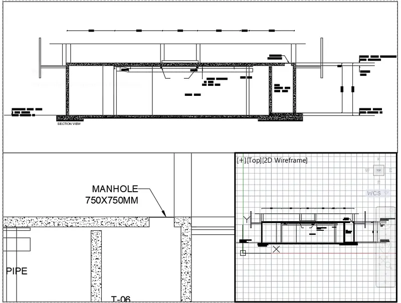
3. Create a layout of the section created in Challenges 9.
Use scale as mentioned in the Figure. Use MV command create multiple viewports. Take a plot.
Aim:
To create the layout of the section created in challenge 9 and to take the plot.
Procedure:
- To create the viewport, initially take the 9th-week challenge that is already created and in that take the industrial section
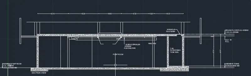

- Now, in the command prompt type V to create the model view of the section.
- Then provide the view name and choose the boundary option
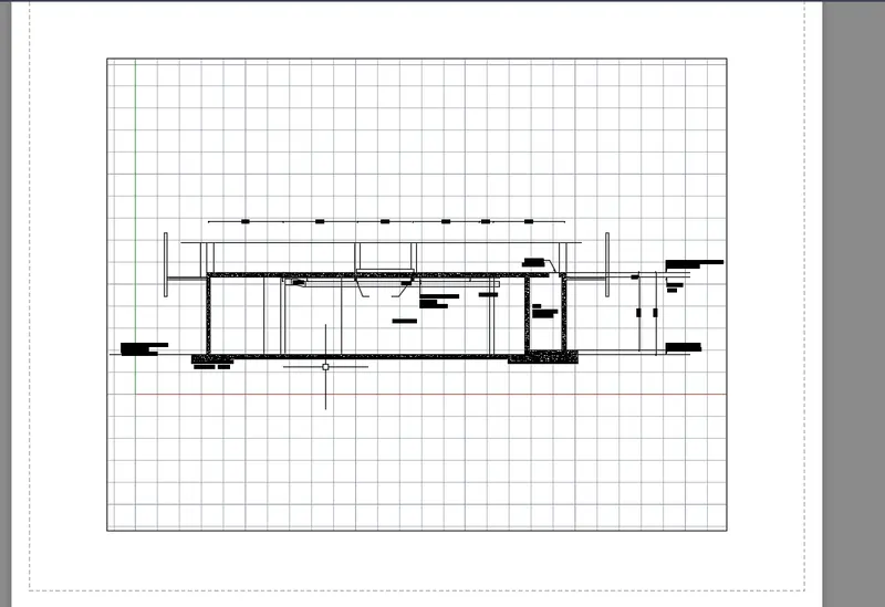
- Now, click ok then apply and again ok.
- Hence, the model view is created.
- Now, go to layout option and select new and type the name of the layout as Section
- Using the MSpace command shift from paper space to model space.

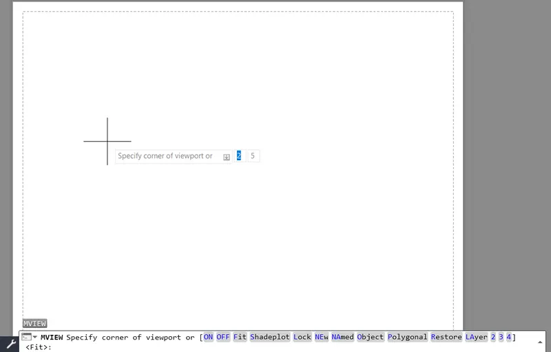
- Now, type MV to create multiple viewports and create viewports as necessary.
- Then provide the views as given in the question.
- Then type ms in command prompt to zoom in and out the views in the viewport and PS command to return back to paper space where zooming in and out is not possible.

RESULT:
All the drawings are drawn using the proper commands and with the given specifications. Mainly layout command and MV command is used in this drawing to technically specify the different components in the drawing.