Creating Kitchen layout, Hatching of Architectural elements and sectional view of an Industrial Building in AutoCad
1.Create the layouts of the Kitchen and provide hatches pattern as shown. Also, use blocks wherever required. Provide appropriate dimensions in the plan. Assume the size of doors, appliances and others as per the standards.
AIM:
To create the layout of the kitchen and hatch them using proper AutoCAD commands.
PROCEDURE:
- Draw a rectangle of proper requirement using rec command.
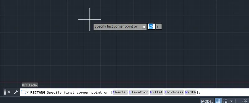
- Specify length of rectangle : 4300mm
- Specify width of rectangle : 3200mm
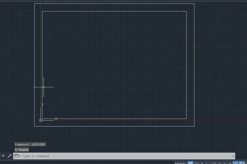
- Using offset command provide proper partition spaces.
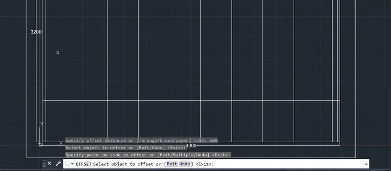
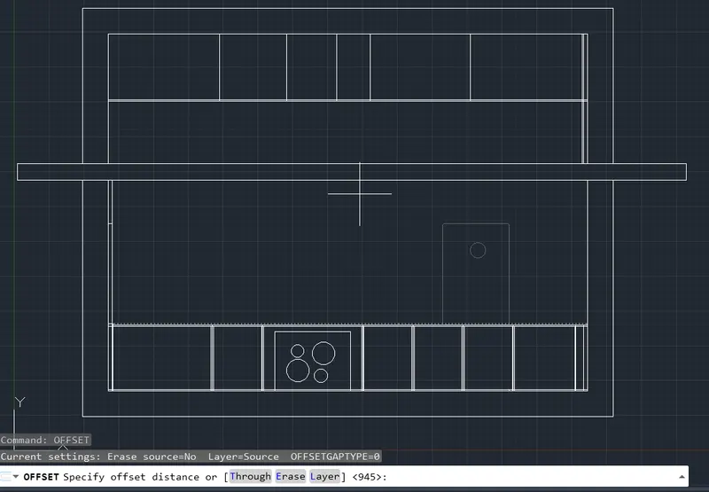
- Then, trim off the unwanted portions with trim command.
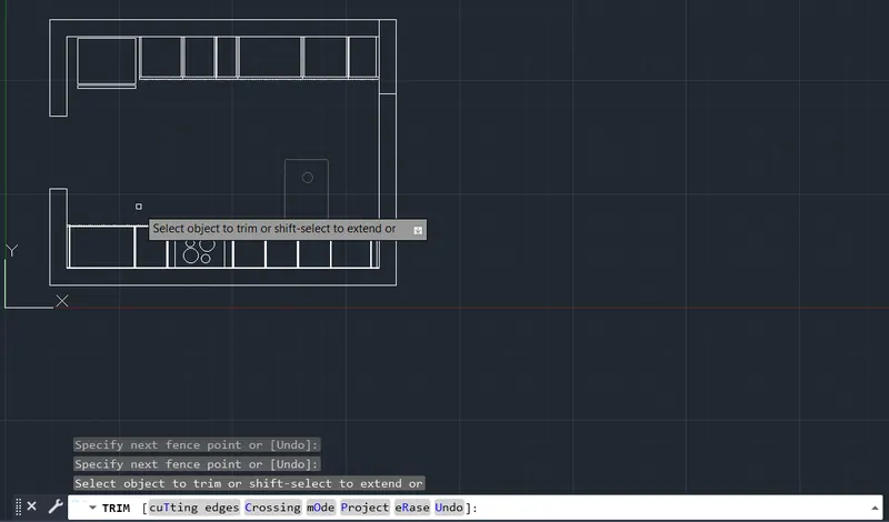
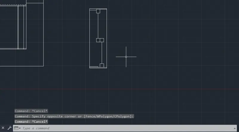
- Draw door component with the help of arc and line command.
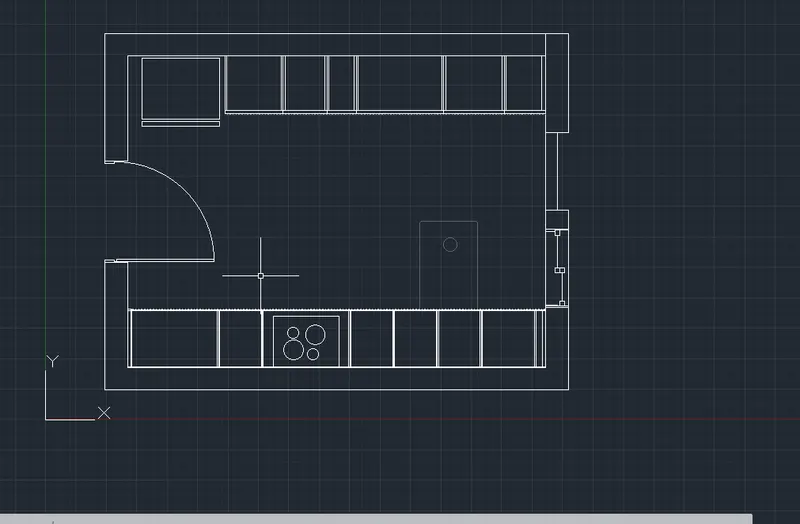
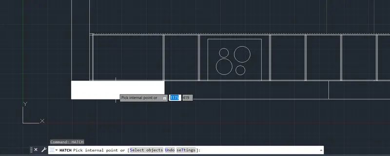
- Using, Hatch command provide hatch to the wall as per the given requirement.
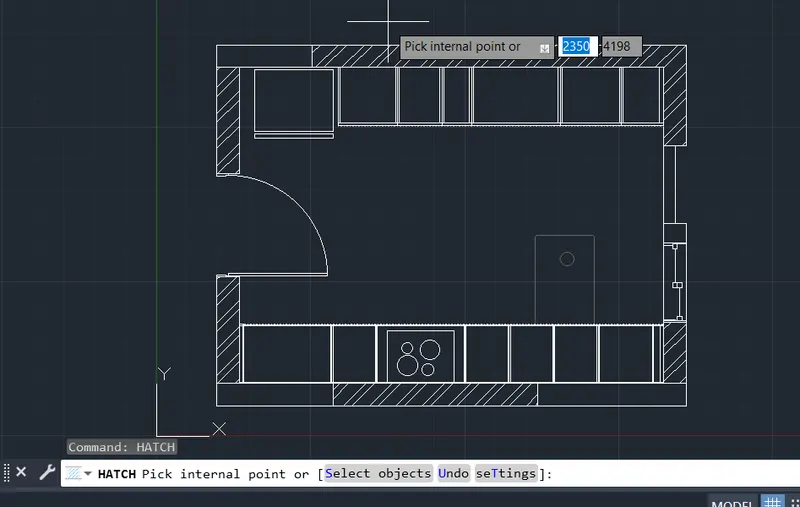
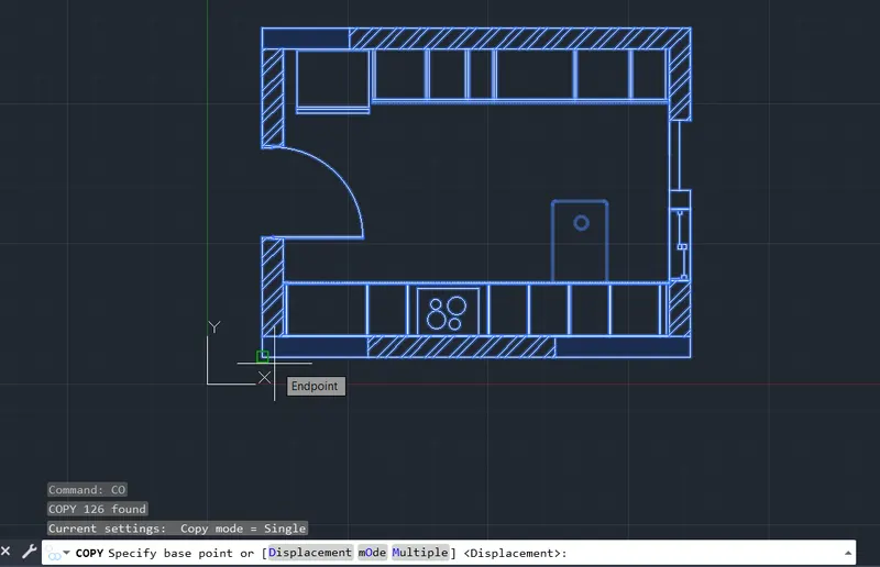
- After that, copy the first kitchen room and create another kitchen space.
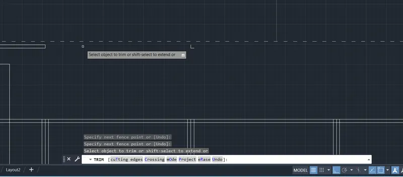
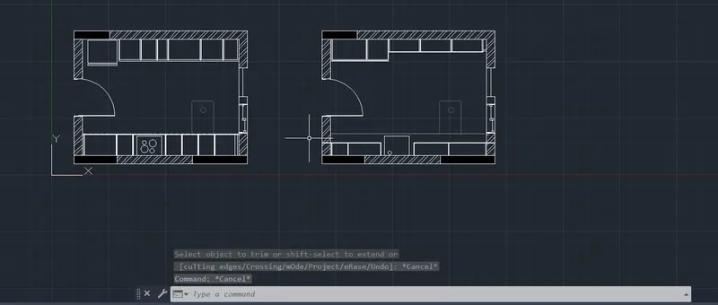
- Then, again use proper hatching tools to specify the wall and components.
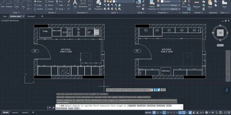
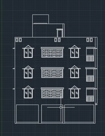
2. Create the elevation of the plan created in the Challenges 7 and apply proper hatch in the walls, doors, windows, and other architectural elements. Refer to the dimensions in Plans and sections in Challenges 7.
Aim:
To create the elevation of the plan that was already created and to apply proper htch in the walls, doors,windows and other architectural elements.
Procedure:
- Initially set the units as Decimal (mm).
- Now, set the limits of the drawing
- Specify the lower left corner: (0,0)
- Specify the upper right corner: (10000,10000)

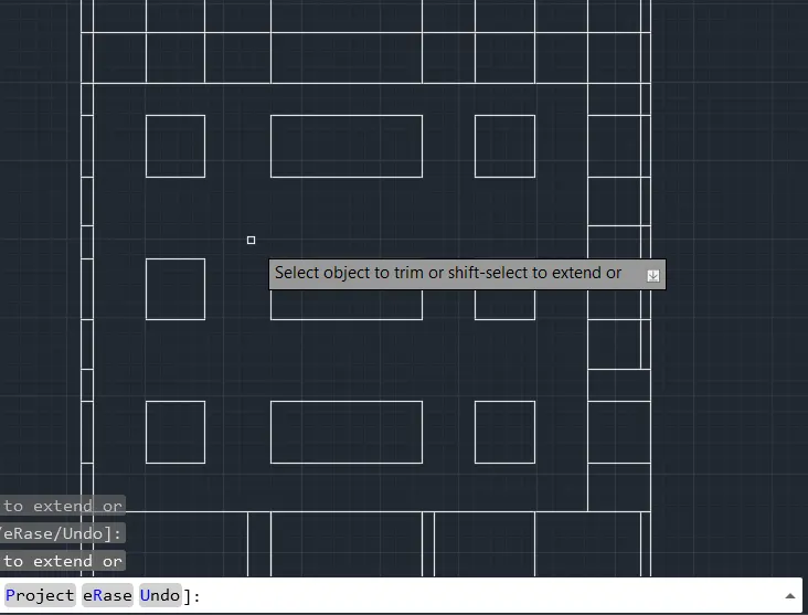
- Using the Xline take reference from the challenge 7 drawing.
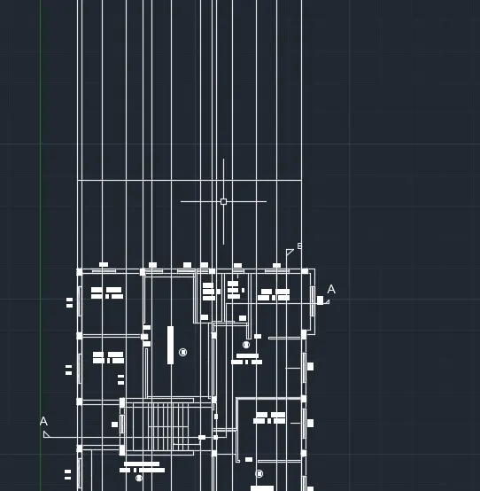
- With the help of offset command draw windows and floor levels.
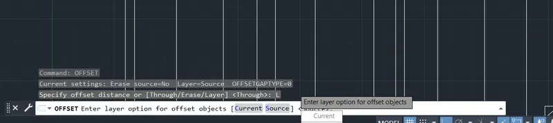
- After that, by using trim command trim off the unwanted lines.
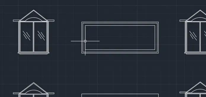
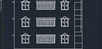
- Using the hatch command, hatch the windows as per the drawing requirement.
- Provide text using the Mtext command.
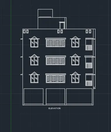
3. Create the section view of an industrial building as shown in Figure. Provide appropriate hatches and dimensions wherever required. Also, provide annotations to the drawing.
Aim:
To create the section view of an industrial building and provide appropriate hatching and dimensions as required and also provide annotations to the drawing.
Procedure:
- Initially set the units as Decimal (mm).
- Now, set the limits of the drawing
- Specify the lower left corner: (0,0)
- Specify the upper right corner: (10000,10000)
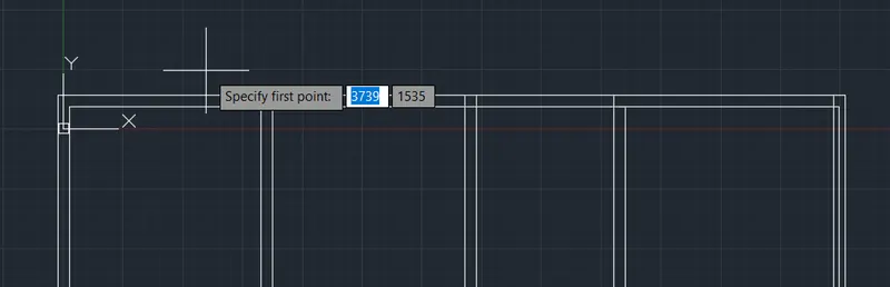
- Use line command to create the outline of industrial building.
- Offset command can be used to offset the lines wherever required.
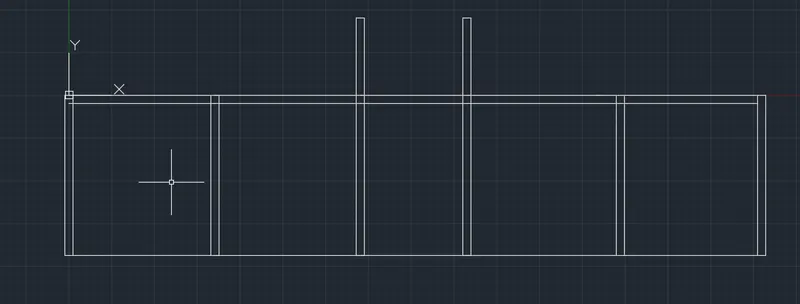
- By using trim command, trim off the unwanted components.
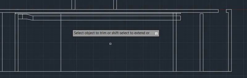
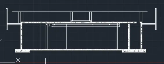
- Now, provide necessary hatching (AR.CONC)in the drawing.
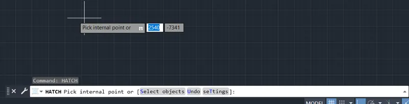
- Using the hatch command, provide proper hatching as per the scale.
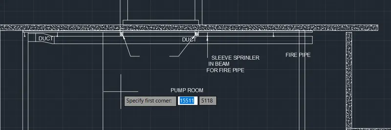
- After completion of all the components, provide text using the Mtext command.


- Then, by using the Mleader command provide proper texts for the components.
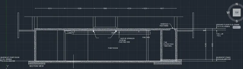
RESULT:
All the drawings are drawn using the proper commands and with the given specifications. Mainly hatch command is used in this drawings to technically specify the different components in the drawing.