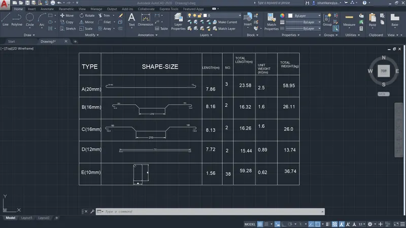
Creating Bar Bending schedule, Different Door types, and Creation of standard drawing templates using AutoCad
1. AIM- TO CREATE THE TEMPLATES BY USING AUTOCAD
INTRODUCTION-> AUTOCAD IS SOFTWARE. IT IS USE FOR SKETCHING AND DRAFTING THE DRAWING
COMMAND USING TO CREATE THE TEMPLATES
- Line- Start the Line command by clicking the Line button on the Draw panel on the Ribbon, or by entering L and then pressing Enter. Draw line segments by picking several random points. Terminate the command by pressing Enter, Esc, or the spacebar. Press Enter or the spacebar to repeat the Line command.
- Dimensions- You can select objects or points on objects to dimension, and then click to place the dimension line. When you hover over an object, the DIM command automatically generates a preview of a suitable dimension type to use. Supported dimension types include vertical, horizontal, and aligned linear dimensions.
- Text- Select text command from the Annotation menu of the Home tab of this software. We have two types of text commands in auto cad. One is Multiline text, and the other is Single line text. You can use any one of the text commands according to your requirement.
- Fillet- Select the Fillet command from the ribbon panel, Or Type F on the command line or command prompt and press Enter. then select the first object, Type R or Radius. Enter. Then Specify the radius of the Fillet and press Enter and Select the second object.
- Trim- Click Home tab Modify panel Trim. Find. Select the objects to serve as cutting edges. Press Enter when you finish selecting the cutting edges. Select the objects to trim and press Enter a second time when you finish selecting the objects to trim.
- Offset- We can offset any object through a point or at a specified distance. We can create as many parallel lines and curves as with the help of the offset command.
- Layer command- The layer command is used to control and manage the drawings in AutoCAD for different purposes. It increases the display performance of the AutoCAD by hiding the portion of our drawing when needed. It also improves the visual complexity of the drawing.
- Hatch command-Go to the Draw panel on the Home tab>You will see a Hatch creation tab>Further specify the pattern on the Pattern panel>Choose your desired method>Pick Points or Select Boundary Objects>After filling the area, hit Enter to apply the hatch.
- Construction lines- Click Home tab Draw panel Construction Line> Specify a point to define the root of the construction line > Specify a second point through which the construction line should pass and enter.
-
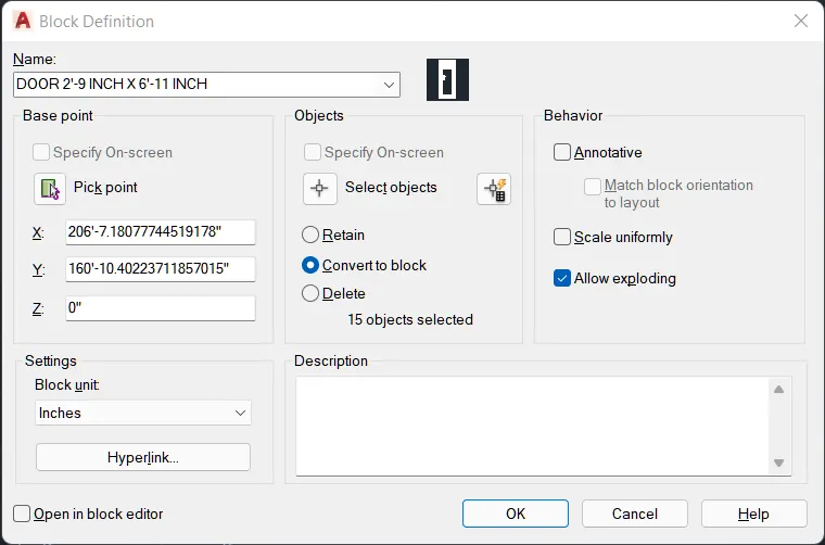
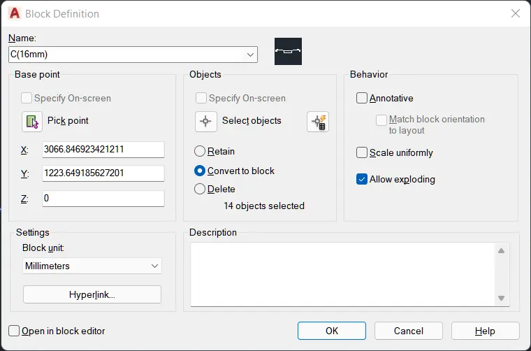
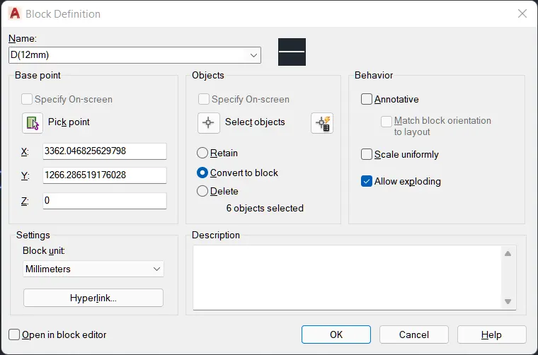
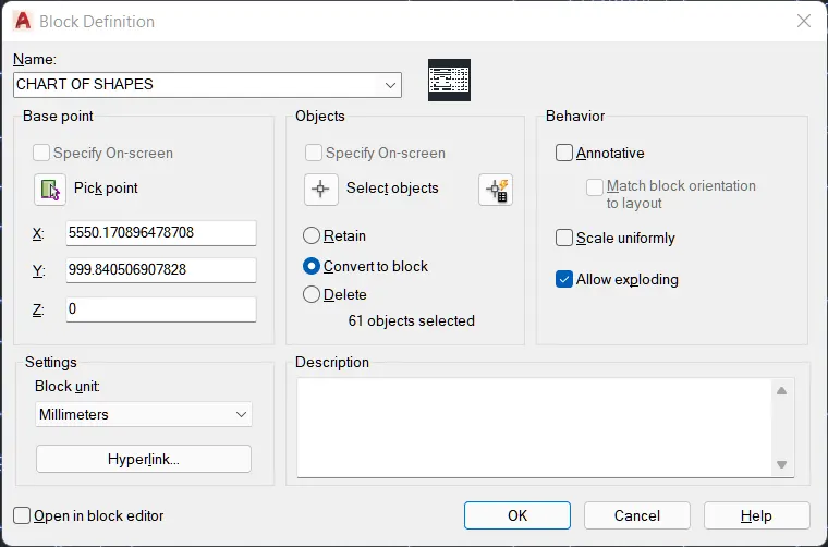
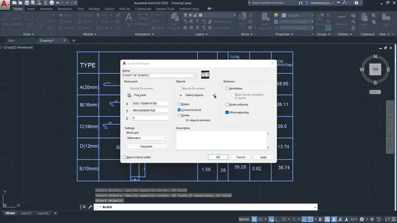
Block command- Choose Home tab> Block panel> Create to start the BLOCK command. The Block Definition dialog box opens.
PROCEDURE->
- SELECT UNIT COMMAND > SELECT DECIMAL> SELECT PRECISION 0(ZERO)-> SELECT SCALE MM-> PRESS OK
- SELECT XLINE COMMAND> SELECT VERTICAL OPTION> SPECIFY POINT PRESS ENTER
- SELECT XLINE COMAND AGAIN > SELECT HORIZONTAL OPTION > SPECIFY POINT PRESS ENTER
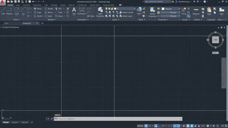
- SELECT OFFSET COMMAND > SPECIF DISTANCE > SELECT OBJECT > SPECIFY SIDE > PRESS ENTER
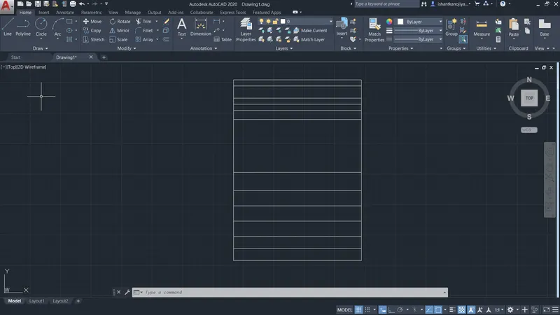
- CREATE LAYER FOR REFERENCE LINE
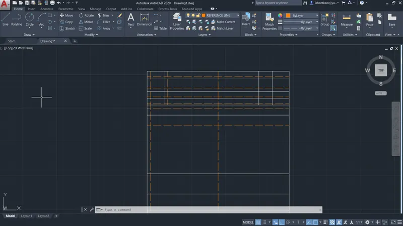
- SELECT ATTDEF COMMAND > SPECIFY TAG > SPECIFY PROMPT > SPECIFY DEFAULT > SPECIFY POINT >PRESS ENTER
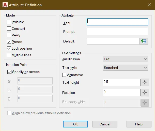
- SPECIFY ALL TAGS AND PLACE THEM AT THEIR POINT
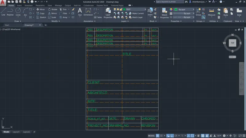
- DELETE REFERENCE LINE
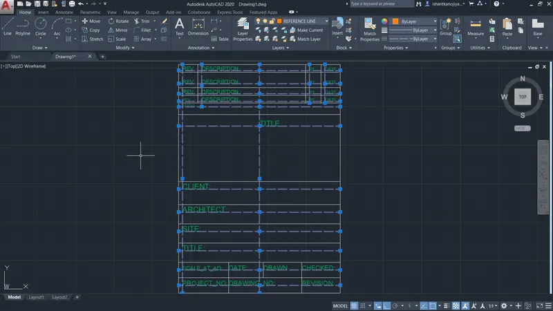
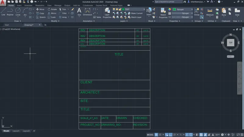
- CONVERT BLOCK
- SELECT B(BLOCK) COMMAND -> TYPE BLOCK NAME(Custom1_titleblock)-> SPECIFY PICKPOINT -> SPECIFY OBJECT (HOLE OBJECT)-> SELECT CONVERT INTO BLOCK > PRESS OK
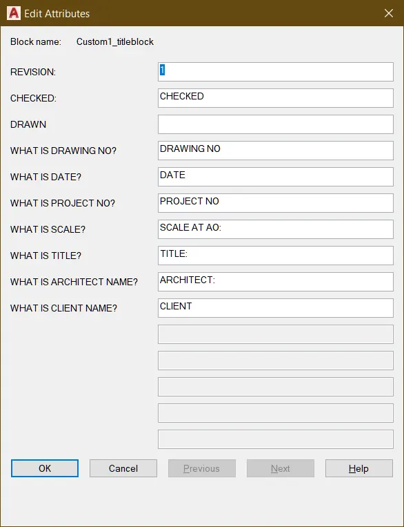
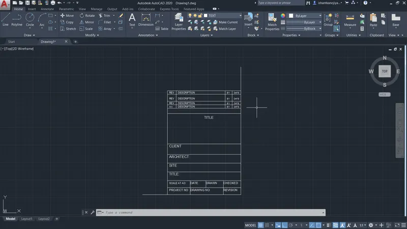
RESULT:
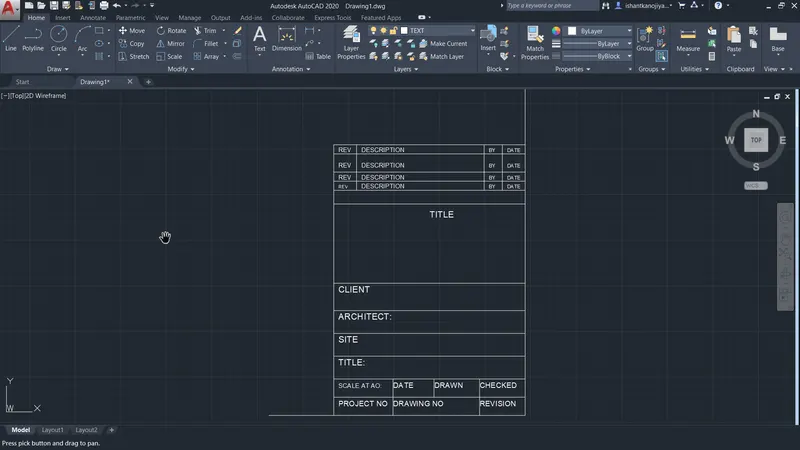
2. PROCEDURE
- SELECT UNIT COMMAND > SELECT DECIMAL> SELECT PRECISION 0(ZERO)-> SELECT SCALE MM-> PRESS OK
- SELECT XLINE COMMAND> SELECT VERTICAL OPTION> SPECIFY POINT PRESS ENTER
- SELECT XLINE COMAND AGAIN > SELECT HORIZONTAL OPTION > SPECIFY POINT PRESS ENTER
- SELECT OFFSET COMMAND > SELECT DISTANCE > SELECT OBJECT >SPECIFY SIDE PRESS ENTER
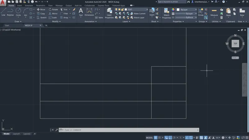
- OFFSET THE LINES
- SKETCH THE REFERENCE LINE FOR PROPER ALIGNMENT OF TEST
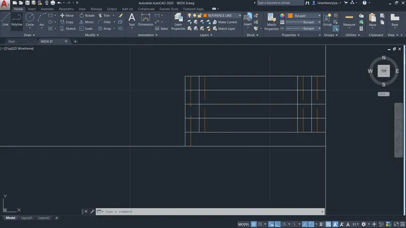
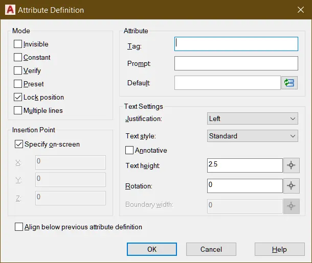
- SELECT ATTDEF COMMAND > SPECIFY TAG> SPECIFY PROMPT> SPECIFY DEFAULT> PRESS OK
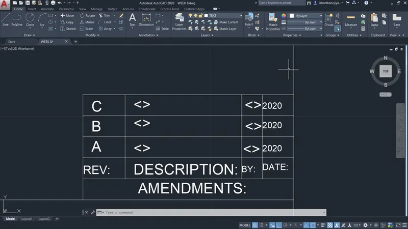
- SPECIFY TAGS IN AT THEIR LOCATION
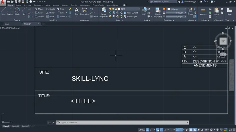
- SPECIFY ALL TAGS
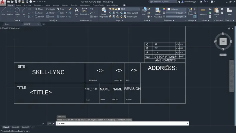
- CONVERT INTO BLOCK
- SELECT BLOCK COMMAND> SELECT PICK POINT> SELECT OBJECT> SPECIFY BLOCK NAME> SELECT CONVERT INTO BLOCK> PRESS ENTER
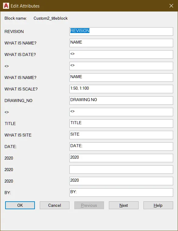
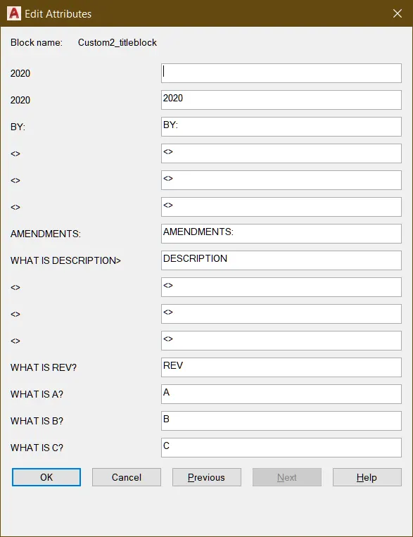
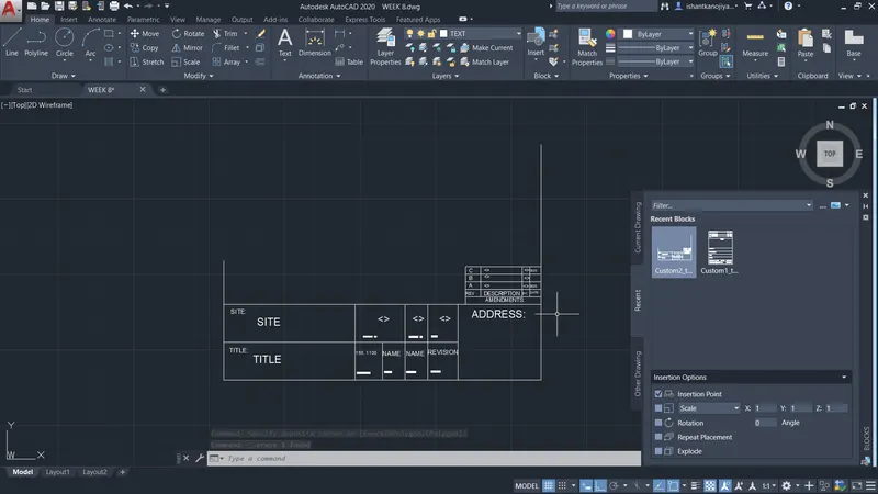
RESULT:
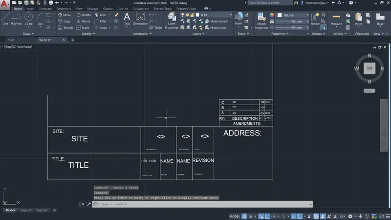
2. AIM: TO CREATE THE DOORS TYPE FOR THE WAREHOUSE AND CONVERT IT INTO A BLOCK USING AUTOCAD
INTRODUCTION: AUTOCAD IS SOFTWARE. IT IS USE FOR SKETCHING AND DRAFTING THE DRAWING
COMMAND USING TO CREATE THE TEMPLATES
- Line- Start the Line command by clicking the Line button on the Draw panel on the Ribbon, or by entering L and then pressing Enter. Draw line segments by picking several random points. Terminate the command by pressing Enter, Esc, or the spacebar. Press Enter or the spacebar to repeat the Line command.
- Dimensions- You can select objects or points on objects to dimension, and then click to place the dimension line. When you hover over an object, the DIM command automatically generates a preview of a suitable dimension type to use. Supported dimension types include vertical, horizontal, and aligned linear dimensions.
- Text- Select text command from the Annotation menu of the Home tab of this software. We have two types of text commands in auto cad. One is Multiline text, and the other is Single line text. You can use any one of the text commands according to your requirement.
- Fillet- Select the Fillet command from the ribbon panel, Or Type F on the command line or command prompt and press Enter. then select the first object, Type R or Radius. Enter. Then Specify the radius of the Fillet and press Enter and Select the second object.
- Trim- Click Home tab Modify panel Trim. Find. Select the objects to serve as cutting edges. Press Enter when you finish selecting the cutting edges. Select the objects to trim and press Enter a second time when you finish selecting the objects to trim.
- Offset- We can offset any object through a point or at a specified distance. We can create as many parallel lines and curves as with the help of the offset command.
- Layer command- The layer command is used to control and manage the drawings in AutoCAD for different purposes. It increases the display performance of the AutoCAD by hiding the portion of our drawing when needed. It also improves the visual complexity of the drawing.
- Hatch command-Go to the Draw panel on the Home tab>You will see a Hatch creation tab>Further specify the pattern on the Pattern panel>Choose your desired method>Pick Points or Select Boundary Objects>After filling the area, hit Enter to apply the hatch.
- Construction lines- Click Home tab Draw panel Construction Line> Specify a point to define the root of the construction line > Specify a second point through which the construction line should pass and enter.
-
Block command- Choose Home tab> Block panel> Create to start the BLOCK command. The Block Definition dialog box opens.
PROCEDURE:
- SELECT UN COMMAND> SELECT DECIMAL>SELECT PRECISION 0.0> SELECT SCALE MM> PRESS OK
- SELECT XLINE> SELECT VERTICAL> SPECIFY SIDE PRESS ENTER
- SELECT XLINE> SELECT HORIZONTAL> SPECIFY SIDE PRESS ENTER
- SELECT FLITE COMMAND > SELECT FIRST LINE > SELECT SECOND LINE> PRESS ENTER
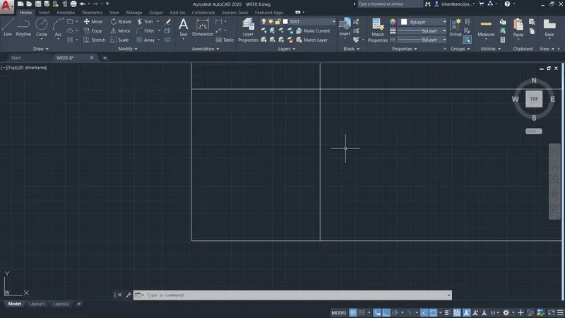
- SKETCH THE DOORS
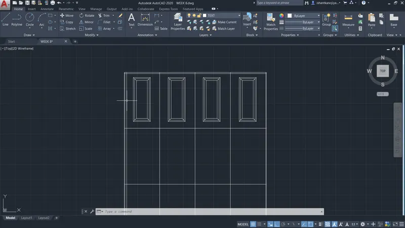
- USING COPY COMMAND
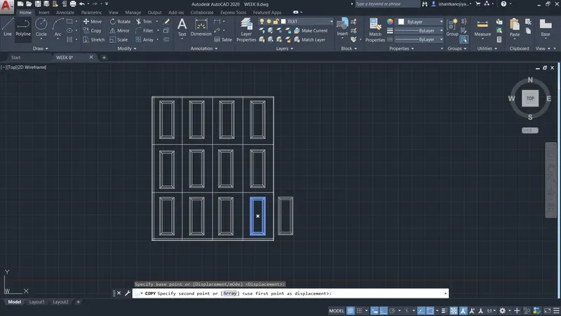
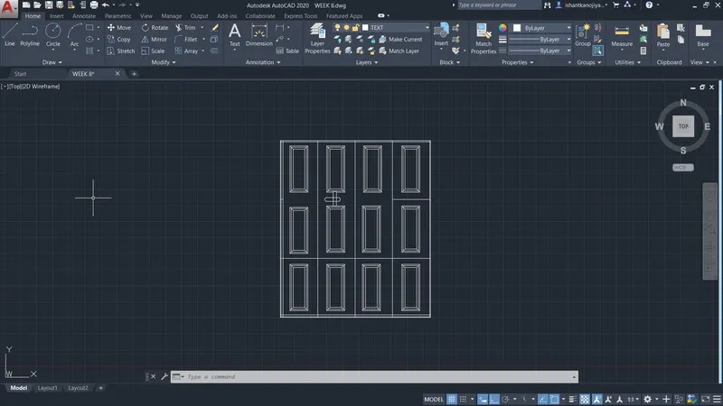
- USING DIMENSION TOOL FOR DIMENSIONING THE LINES
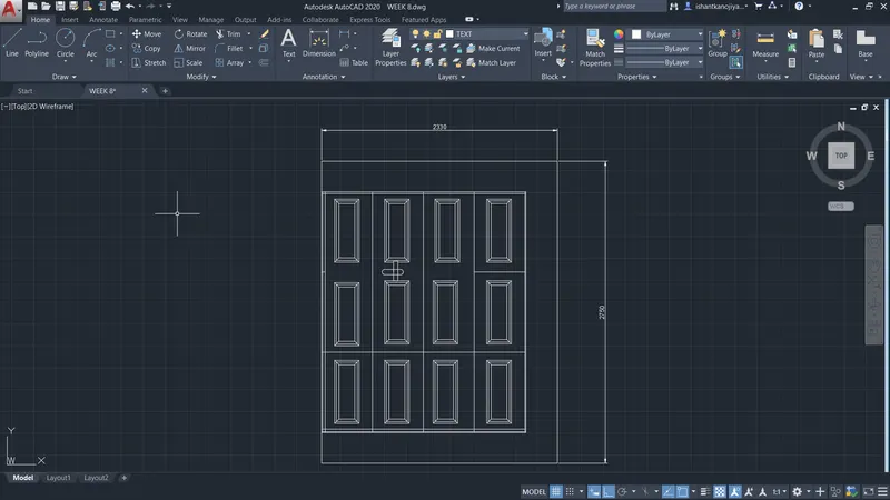
- USING TEXT COMMAND FOR TEXTING
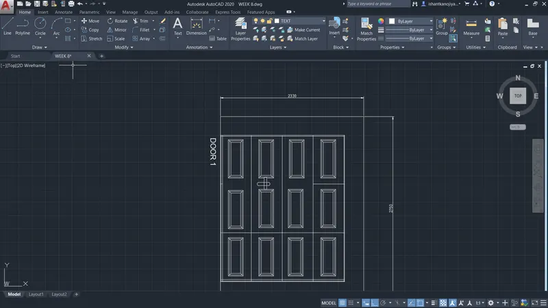
RESULT
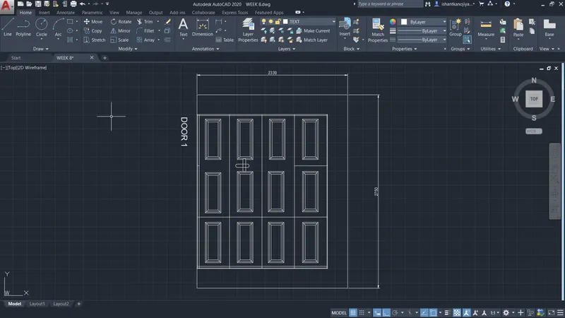
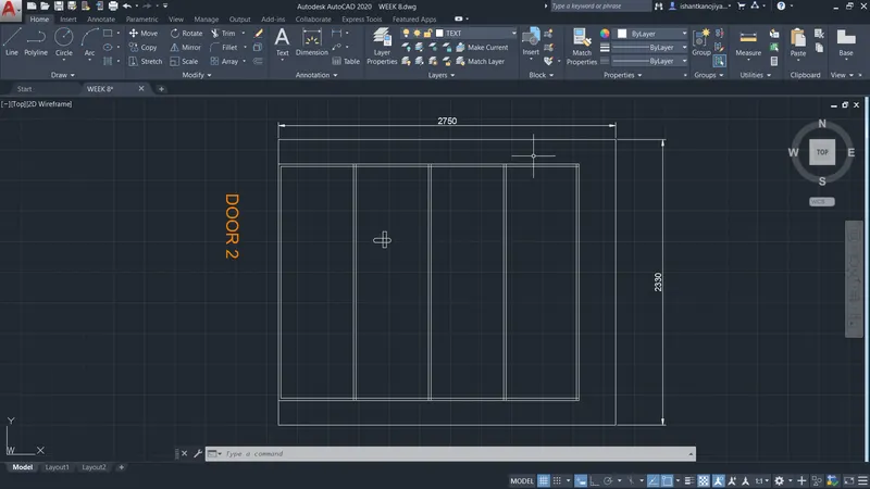
DOOR 2
PROCEDURE:
SAME AS DOOR 1
- SELECT UN COMMAND> SELECT DECIMAL>SELECT PRECISION 0.0> SELECT SCALE MM> PRESS OK
- SELECT XLINE> SELECT VERTICAL> SPECIFY SIDE PRESS ENTER
- SELECT XLINE> SELECT HORIZONTAL> SPECIFY SIDE PRESS ENTER
- SELECT FLITE COMMAND > SELECT FIRST LINE > SELECT SECOND LINE> PRESS ENTER
- OFFSET THE LINE AND TRIM THE LINES
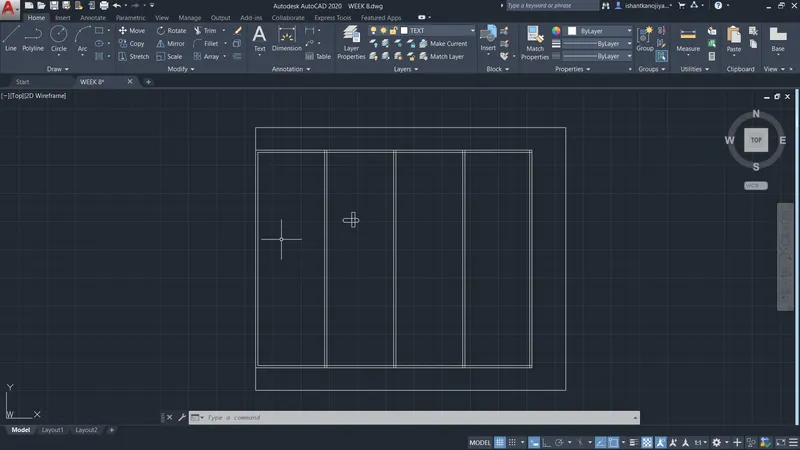
- USING DIMENSION TOOL FOR DIMENSIONING THE LINES
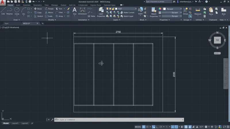
- USING TEXT COMMAND FOR TEXTING
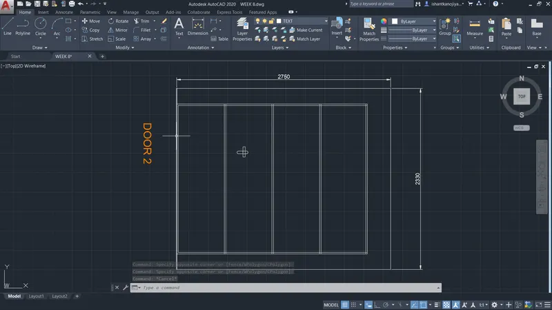
RESULT
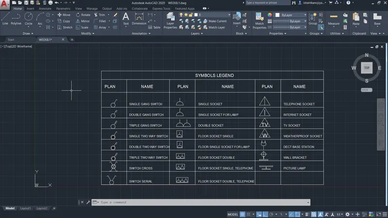
3. AIM: TO CREATE THE SYMBOL AS A BLOCK WITH THE NAME USING AUTOCAD.
INTRODUCTION: AUTOCAD IS SOFTWARE. IT IS USE FOR SKETCHING AND DRAFTING THE DRAWING
COMMAND USING TO CREATE THE TEMPLATES
- Line- Start the Line command by clicking the Line button on the Draw panel on the Ribbon, or by entering L and then pressing Enter. Draw line segments by picking several random points. Terminate the command by pressing Enter, Esc, or the spacebar. Press Enter or the spacebar to repeat the Line command.
- Dimensions- You can select objects or points on objects to dimension, and then click to place the dimension line. When you hover over an object, the DIM command automatically generates a preview of a suitable dimension type to use. Supported dimension types include vertical, horizontal, and aligned linear dimensions.
- Text- Select text command from the Annotation menu of the Home tab of this software. We have two types of text commands in auto cad. One is Multiline text, and the other is Single line text. You can use any one of the text commands according to your requirement.
- Fillet- Select the Fillet command from the ribbon panel, Or Type F on the command line or command prompt and press Enter. then select the first object, Type R or Radius. Enter. Then Specify the radius of the Fillet and press Enter and Select the second object.
- Trim- Click Home tab Modify panel Trim. Find. Select the objects to serve as cutting edges. Press Enter when you finish selecting the cutting edges. Select the objects to trim and press Enter a second time when you finish selecting the objects to trim.
- Offset- We can offset any object through a point or at a specified distance. We can create as many parallel lines and curves as with the help of the offset command.
- Layer command- The layer command is used to control and manage the drawings in AutoCAD for different purposes. It increases the display performance of the AutoCAD by hiding the portion of our drawing when needed. It also improves the visual complexity of the drawing.
- Hatch command-Go to the Draw panel on the Home tab>You will see a Hatch creation tab>Further specify the pattern on the Pattern panel>Choose your desired method>Pick Points or Select Boundary Objects>After filling the area, hit Enter to apply the hatch.
- Construction lines- Click Home tab Draw panel Construction Line> Specify a point to define the root of the construction line > Specify a second point through which the construction line should pass and enter.
-
Block command- Choose Home tab> Block panel> Create to start the BLOCK command. The Block Definition dialog box opens.
PROCEDURE:
- SELECT UN COMMAND > SELECT DECIMAL> SELECT PRECISION 0.0> SELECT SCALE MM> PRESS OK
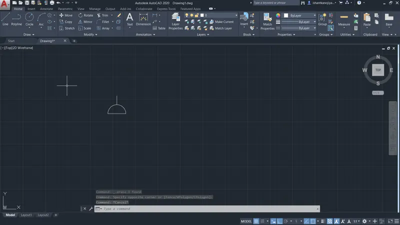
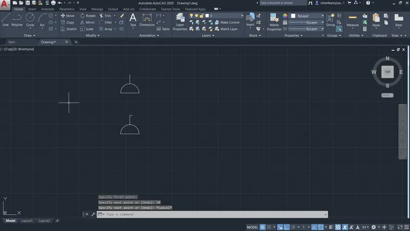
- SKETCH THE PLAN/SYMBOL ONE BY ONE
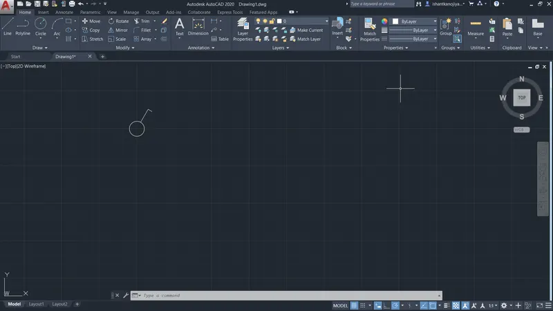
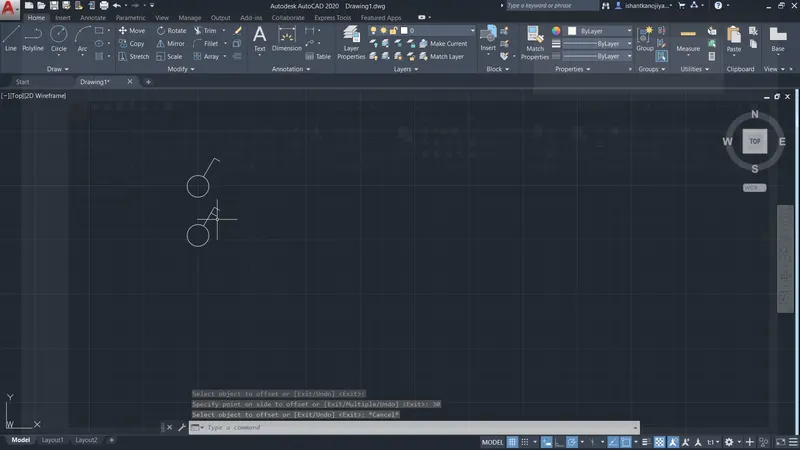
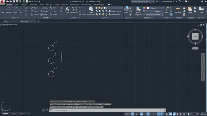
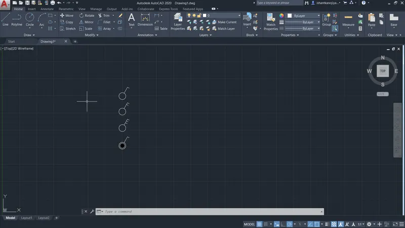
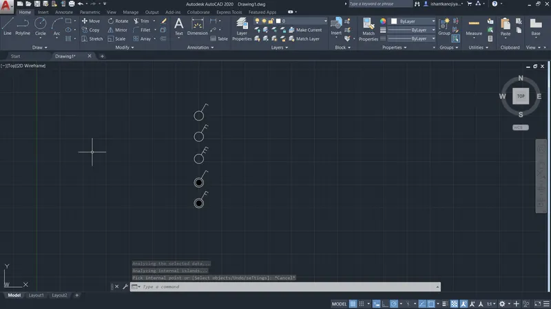
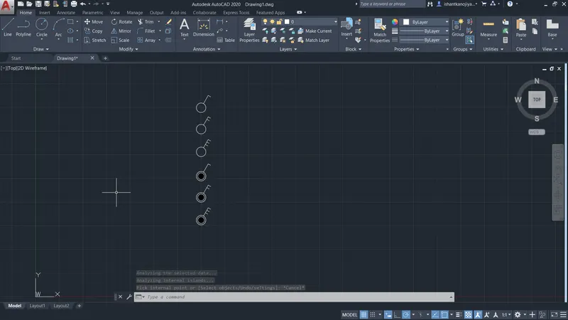
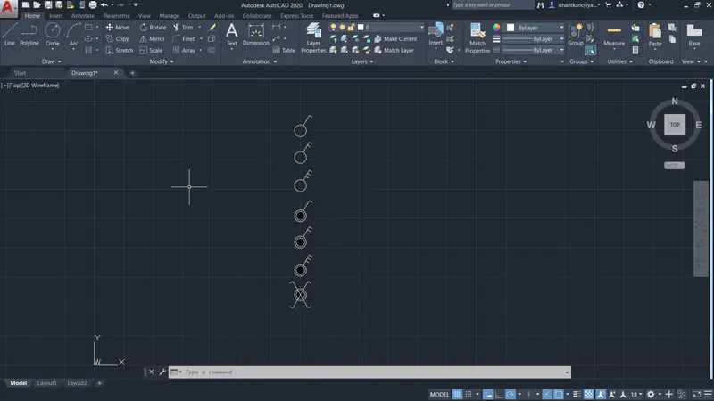
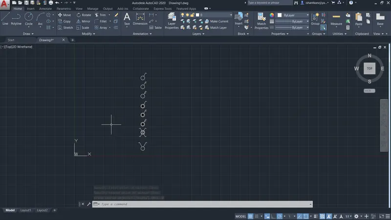
- USING TEXT TOOL FOR TEXTING
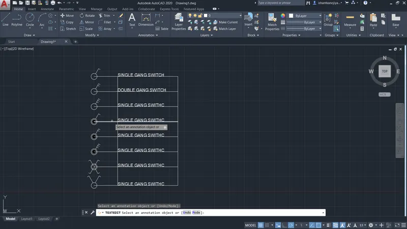
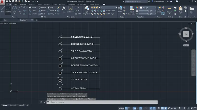
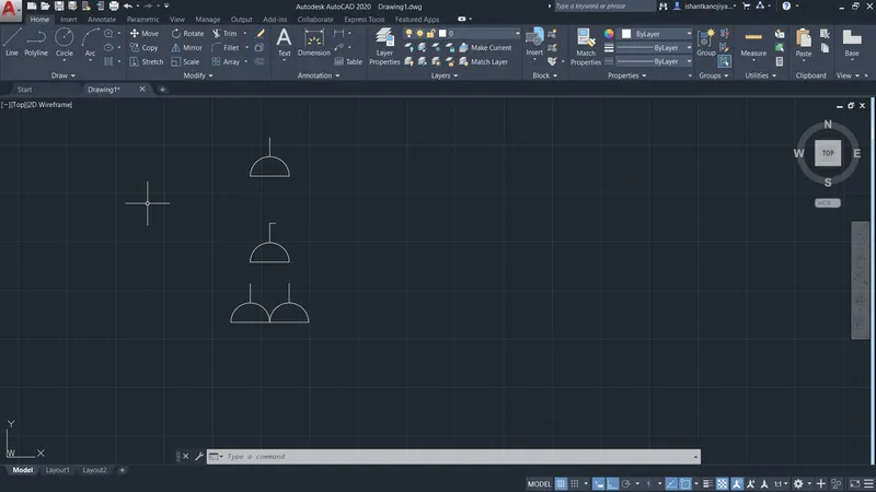
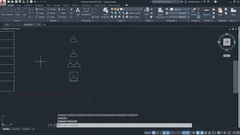
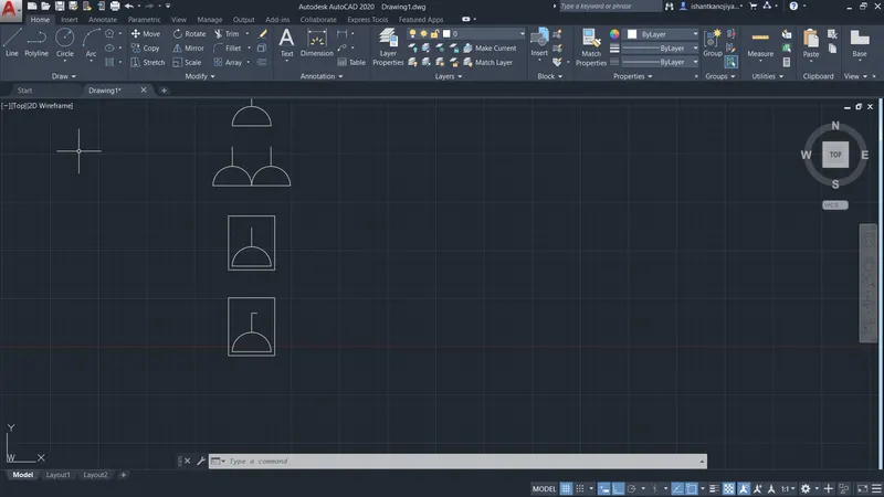
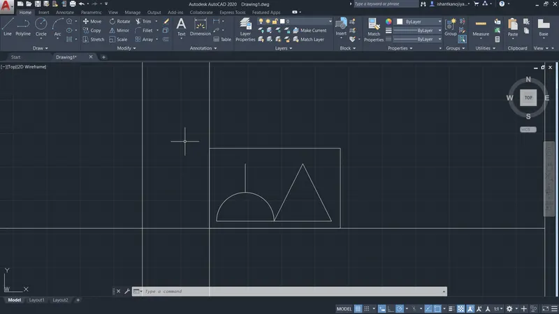
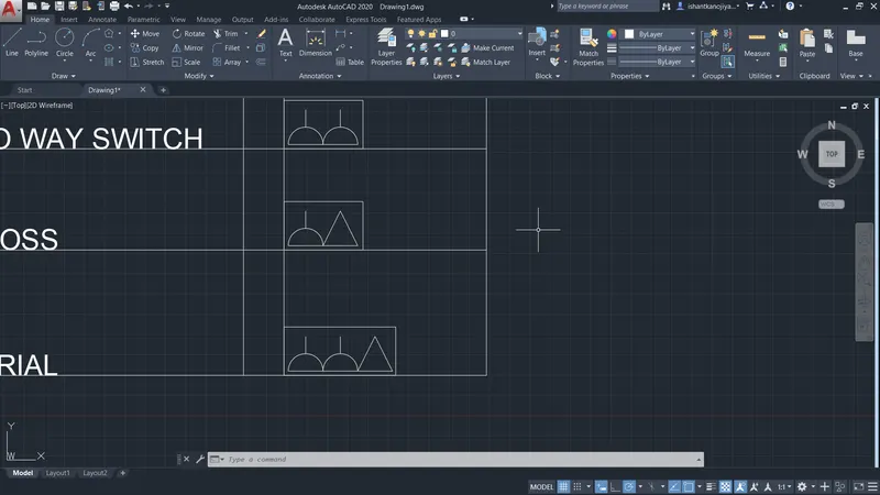
- NAMING OF SOCKET
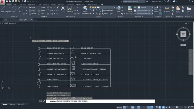
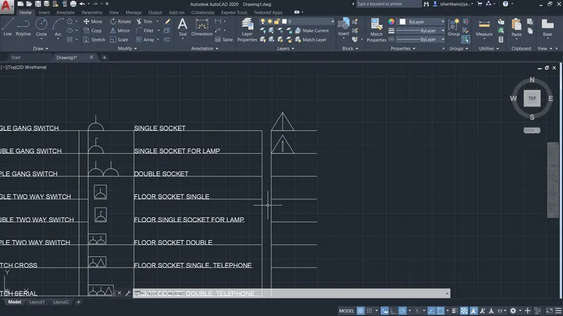
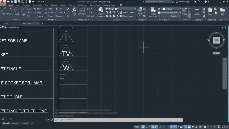
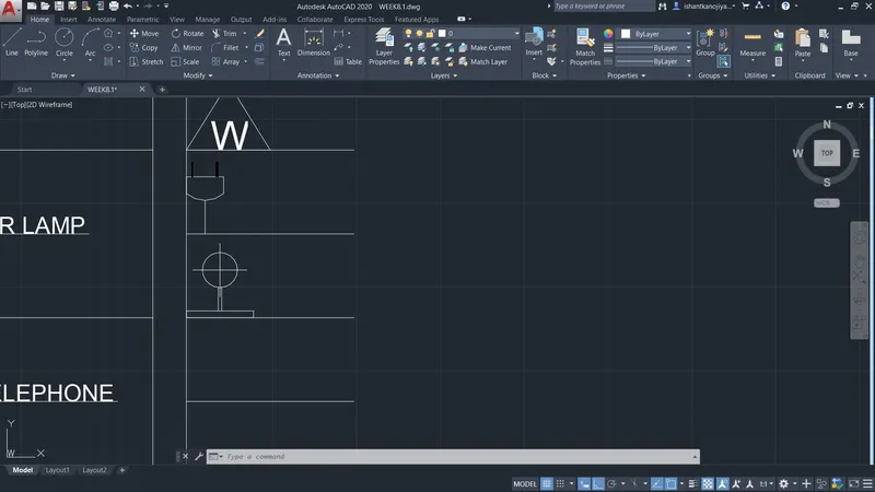
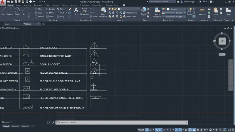
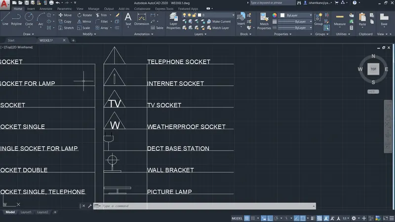
- SKETCH THE BOX PROPERLY
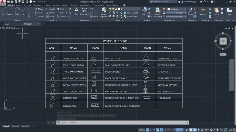
- CONVERT INTO A BLOCK
- SELECT BLOCK COMMAND> SELECT PICK POINT> SELECT OBJECT> SPECIFY NAME> PRESS OK
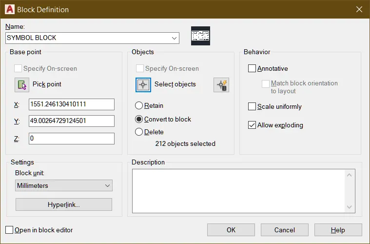
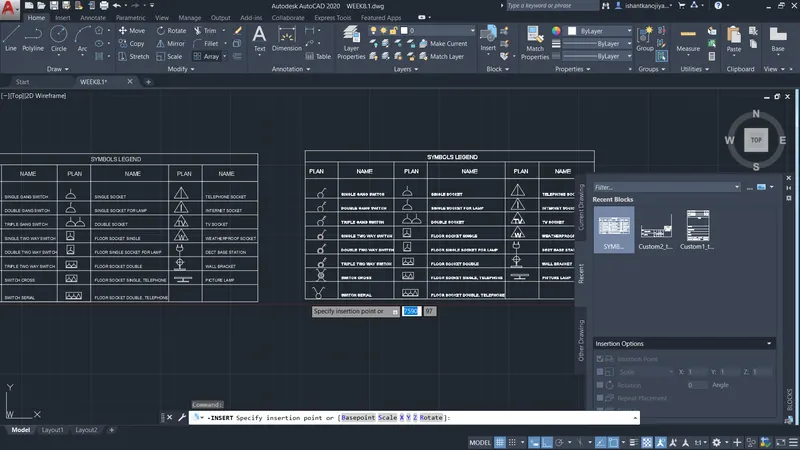
- BLOCK HAS BEEN CREATED
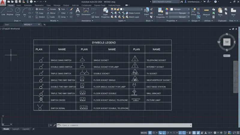
RESULT
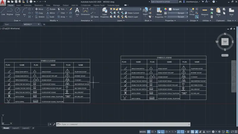
4. AIM: TO CREATE THE DOOR TYPE FOR RESIDENTIAL BUILDINGS AS A BLOCK USING AUTOCAD.
INTRODUCTION: AUTOCAD IS SOFTWARE. IT IS USE FOR SKETCHING AND DRAFTING THE DRAWING
COMMAND USING TO CREATE THE TEMPLATES
- Line- Start the Line command by clicking the Line button on the Draw panel on the Ribbon, or by entering L and then pressing Enter. Draw line segments by picking several random points. Terminate the command by pressing Enter, Esc, or the spacebar. Press Enter or the spacebar to repeat the Line command.
- Dimensions- You can select objects or points on objects to dimension, and then click to place the dimension line. When you hover over an object, the DIM command automatically generates a preview of a suitable dimension type to use. Supported dimension types include vertical, horizontal, and aligned linear dimensions.
- Text- Select text command from the Annotation menu of the Home tab of this software. We have two types of text commands in auto cad. One is Multiline text, and the other is Single line text. You can use any one of the text commands according to your requirement.
- Fillet- Select the Fillet command from the ribbon panel, Or Type F on the command line or command prompt and press Enter. then select the first object, Type R or Radius. Enter. Then Specify the radius of the Fillet and press Enter and Select the second object.
- Trim- Click Home tab Modify panel Trim. Find. Select the objects to serve as cutting edges. Press Enter when you finish selecting the cutting edges. Select the objects to trim and press Enter a second time when you finish selecting the objects to trim.
- Offset- We can offset any object through a point or at a specified distance. We can create as many parallel lines and curves as with the help of the offset command.
- Layer command- The layer command is used to control and manage the drawings in AutoCAD for different purposes. It increases the display performance of the AutoCAD by hiding the portion of our drawing when needed. It also improves the visual complexity of the drawing.
- Hatch command-Go to the Draw panel on the Home tab>You will see a Hatch creation tab>Further specify the pattern on the Pattern panel>Choose your desired method>Pick Points or Select Boundary Objects>After filling the area, hit Enter to apply the hatch.
- Construction lines- Click Home tab Draw panel Construction Line> Specify a point to define the root of the construction line > Specify a second point through which the construction line should pass and enter.
-
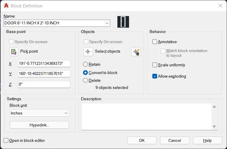
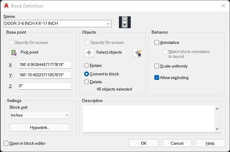
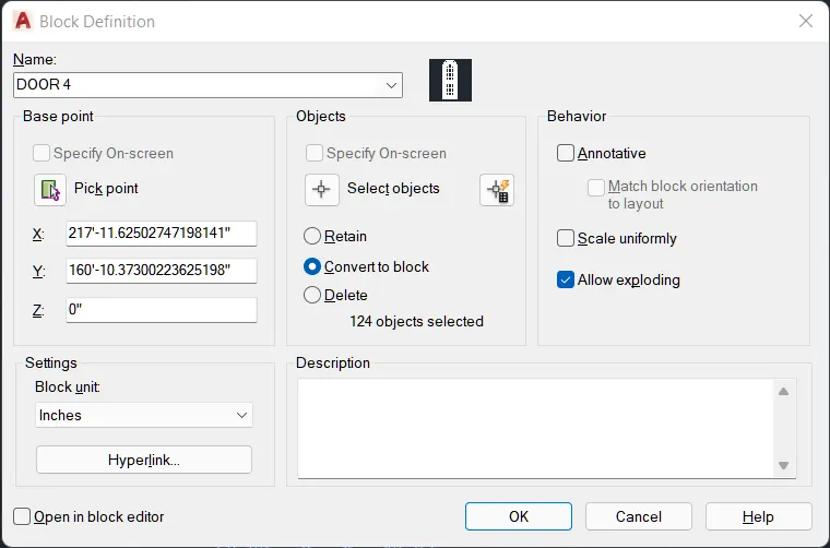
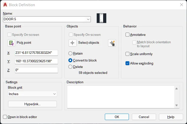
Block command- Choose Home tab> Block panel> Create to start the BLOCK command. The Block Definition dialog box opens.
PROCEDURE:
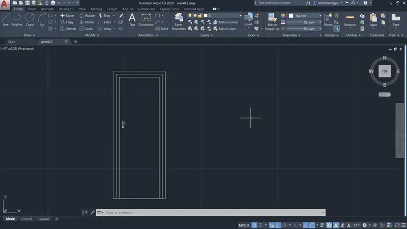
- SELECT UN COMMAND> SELECT ENGINEERING > SELECT PRECISION 0'0"> SELECT SCALE INCHES> PRESS OK
- SELECT RECTANGLE COMMAND> SELECT FIRST POINT> SELECT DIMENSION> SPECIFY SIDE(LENGTH,WIDTH)> SPECIFY SIDE PRESS ENTER
- SELECT OFFSET COMMAND >SELECT DISTANCE> SELECT OBJECT> SELECT SIDE PRESS ENTER
- SKETCH THE HANDEL
- SELECT TEXT COMMAND FOR TEXTING
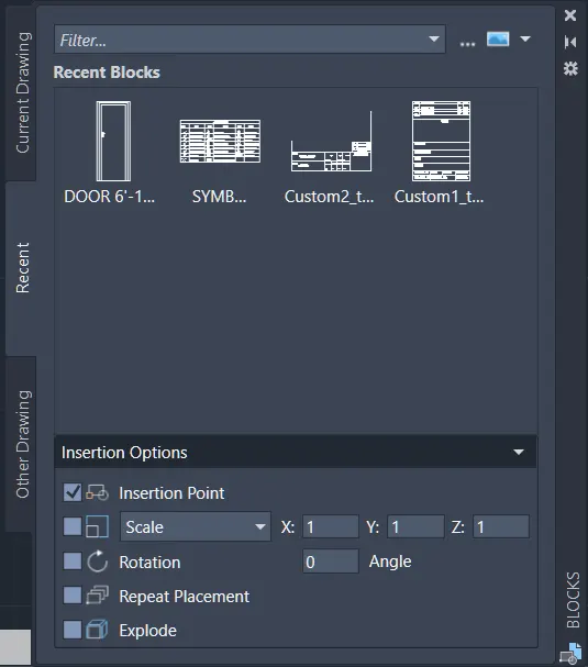
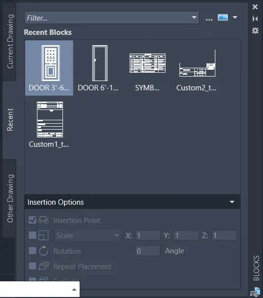
- SELECT BLOCK COMMAND> SELECT PICK POINT > SELECT OBJECT> SPECIFY SIDE> SELECT CONVERT INTO BLOCK> PRESS OK
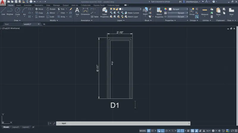
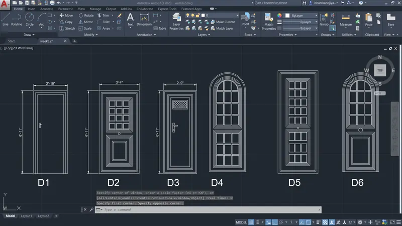
SKETCHING D1
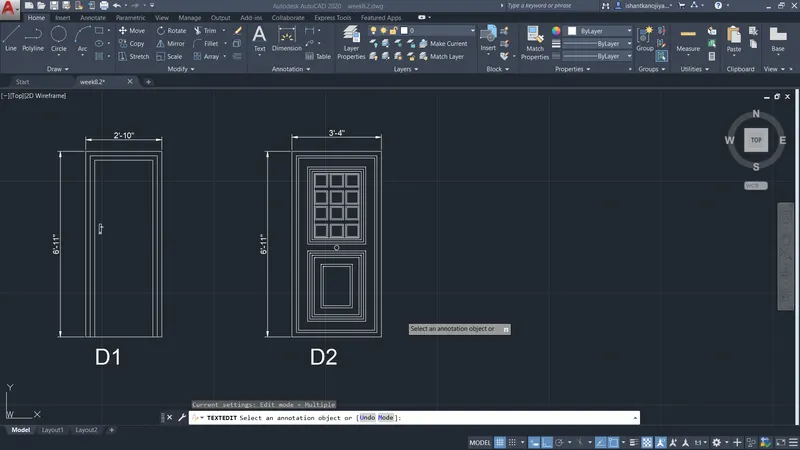
SKETCHING D2
SKETCHING D3
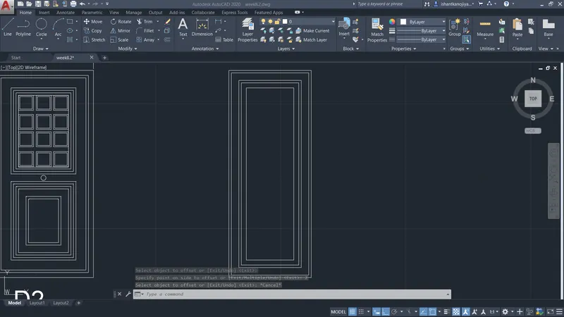
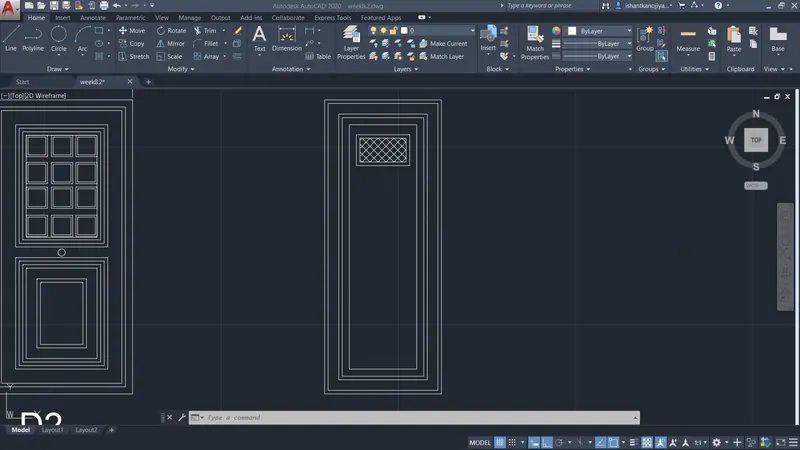
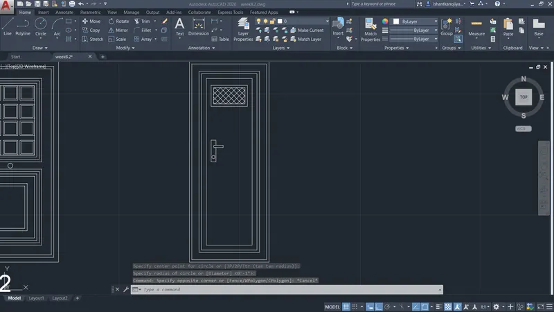
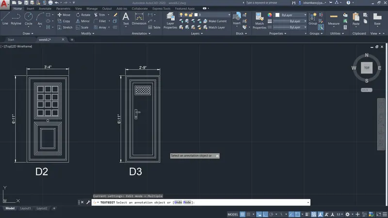
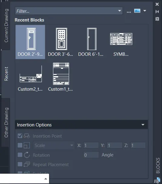
SKETCHING D4
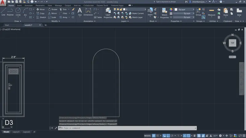
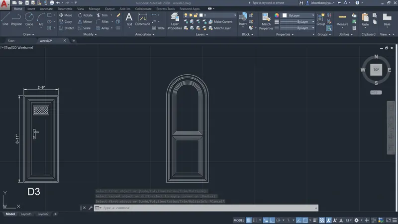
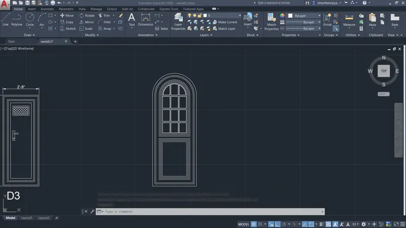
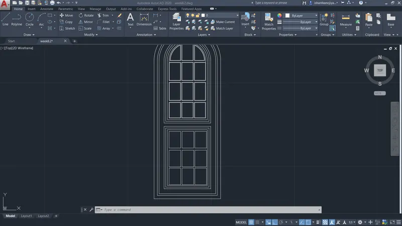
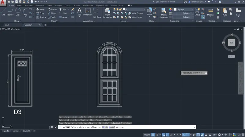
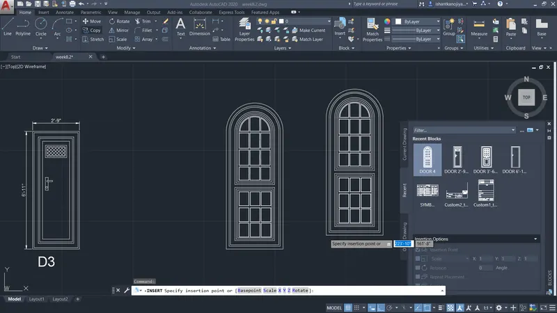
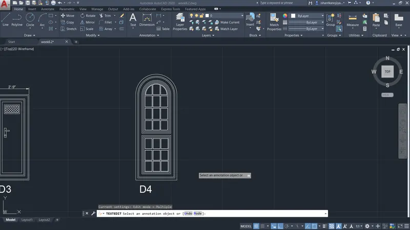
SKETCHING D5
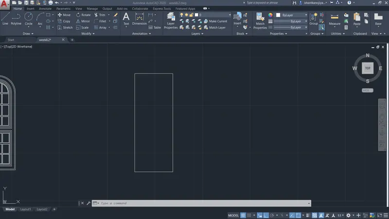
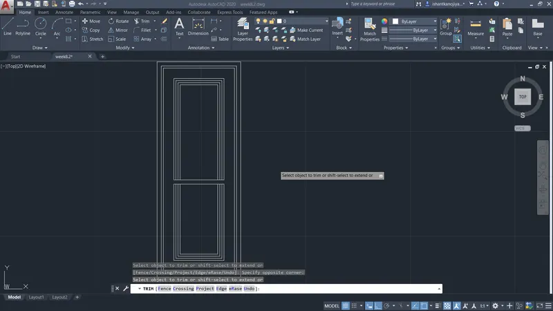
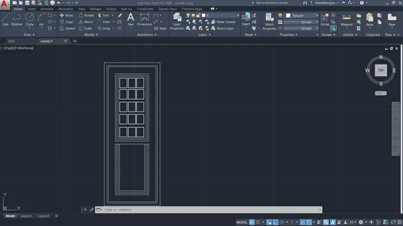
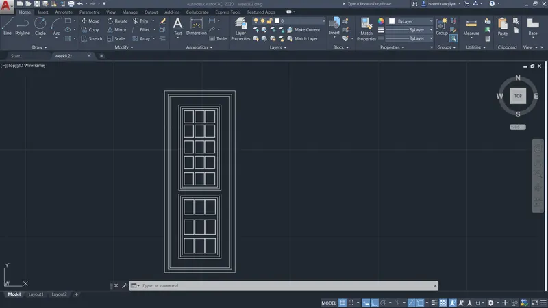
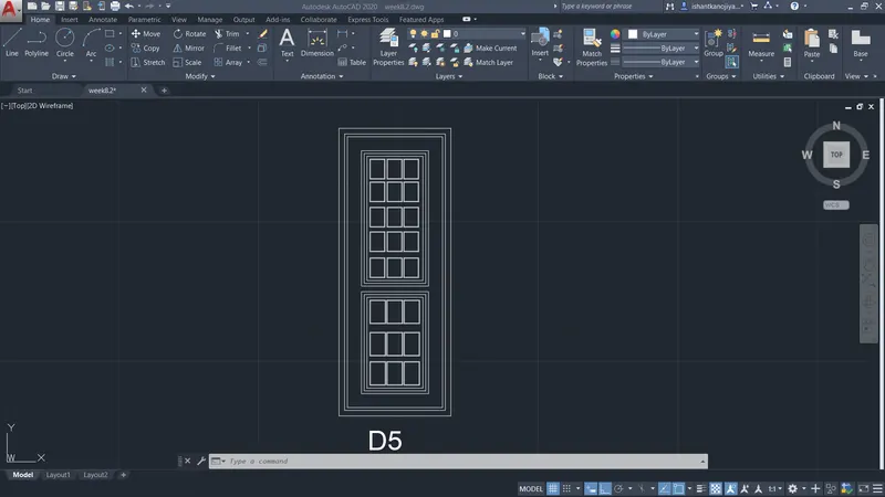
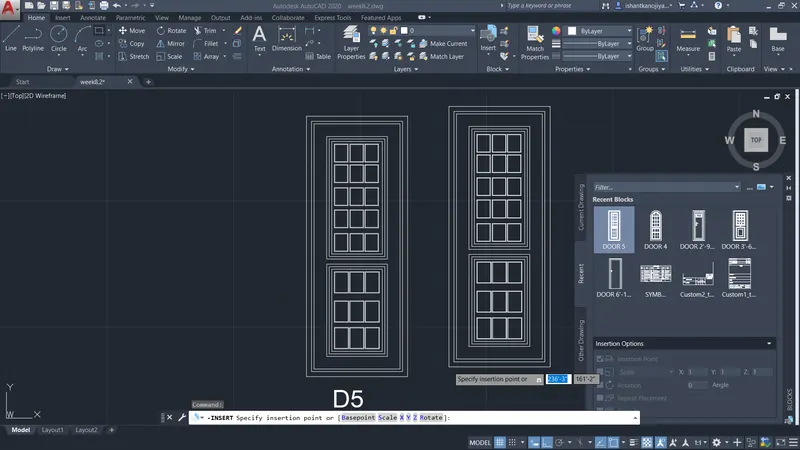
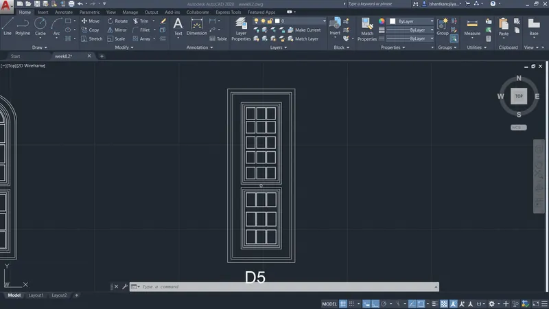
SKETCHING D6
- COPY THE DOOR 4
- EDIT THE DOOR 4
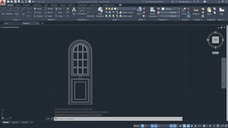
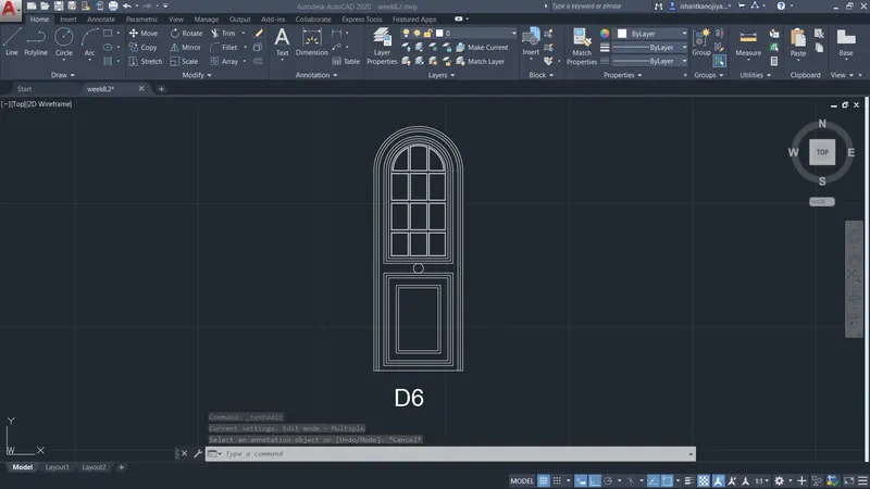
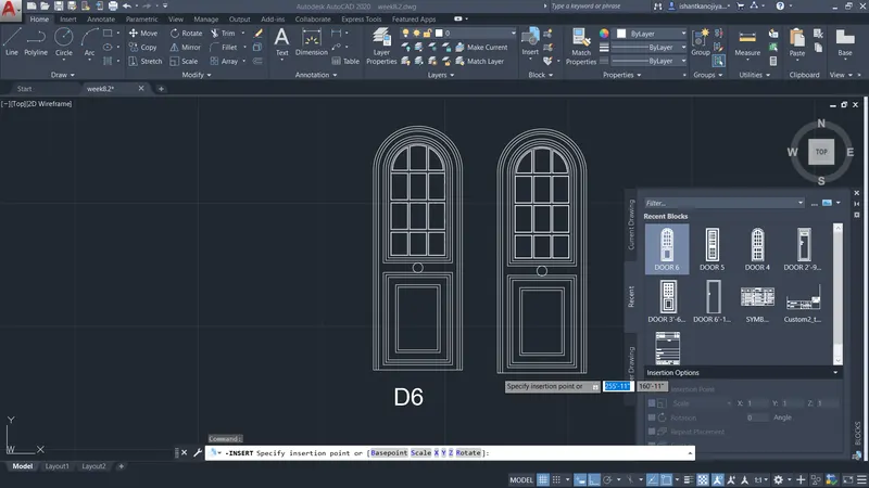
RESULT
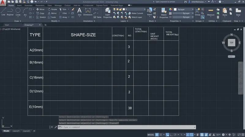
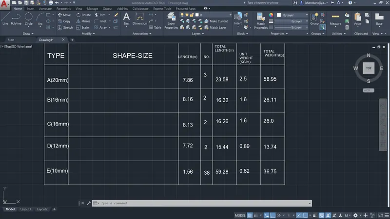
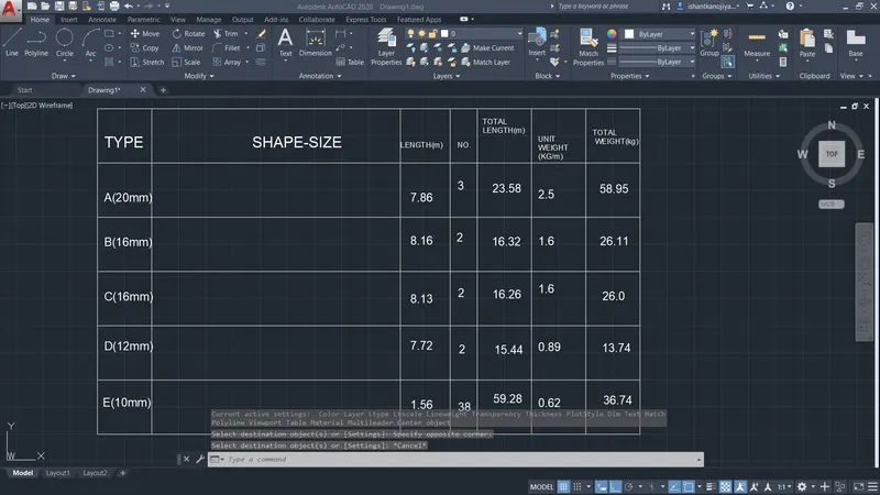
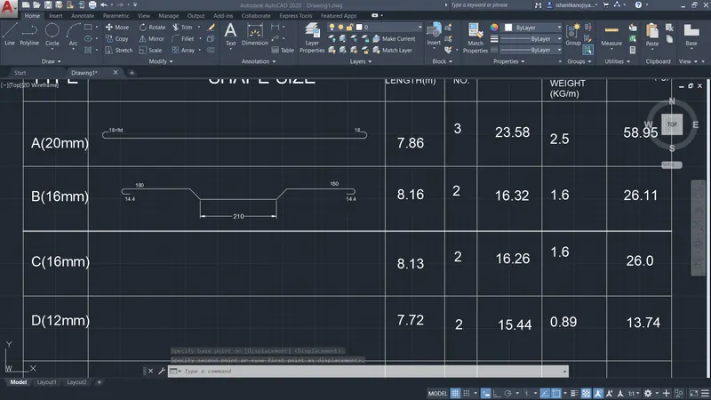
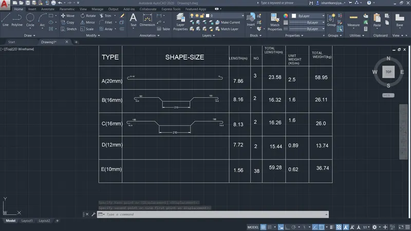
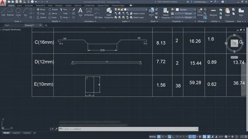
5. AIM: TO CREATE THE SHAPES AS BLOCK AND INSERT INTO THE TABLE USING AUTOCAD
INTRODUCTION: AUTOCAD IS SOFTWARE. IT IS USE FOR SKETCHING AND DRAFTING THE DRAWING
COMMAND USING TO CREATE THE TEMPLATES
- Line- Start the Line command by clicking the Line button on the Draw panel on the Ribbon, or by entering L and then pressing Enter. Draw line segments by picking several random points. Terminate the command by pressing Enter, Esc, or the spacebar. Press Enter or the spacebar to repeat the Line command.
- Dimensions- You can select objects or points on objects to dimension, and then click to place the dimension line. When you hover over an object, the DIM command automatically generates a preview of a suitable dimension type to use. Supported dimension types include vertical, horizontal, and aligned linear dimensions.
- Text- Select text command from the Annotation menu of the Home tab of this software. We have two types of text commands in auto cad. One is Multiline text, and the other is Single line text. You can use any one of the text commands according to your requirement.
- Fillet- Select the Fillet command from the ribbon panel, Or Type F on the command line or command prompt and press Enter. then select the first object, Type R or Radius. Enter. Then Specify the radius of the Fillet and press Enter and Select the second object.
- Trim- Click Home tab Modify panel Trim. Find. Select the objects to serve as cutting edges. Press Enter when you finish selecting the cutting edges. Select the objects to trim and press Enter a second time when you finish selecting the objects to trim.
- Offset- We can offset any object through a point or at a specified distance. We can create as many parallel lines and curves as with the help of the offset command.
- Layer command- The layer command is used to control and manage the drawings in AutoCAD for different purposes. It increases the display performance of the AutoCAD by hiding the portion of our drawing when needed. It also improves the visual complexity of the drawing.
- Hatch command-Go to the Draw panel on the Home tab>You will see a Hatch creation tab>Further specify the pattern on the Pattern panel>Choose your desired method>Pick Points or Select Boundary Objects>After filling the area, hit Enter to apply the hatch.
- Construction lines- Click Home tab Draw panel Construction Line> Specify a point to define the root of the construction line > Specify a second point through which the construction line should pass and enter.
-
Block command- Choose Home tab> Block panel> Create to start the BLOCK command. The Block Definition dialog box opens.
PROCEDURE:
- SELECT UN COMMAND >SELECT DECIMAL > SELECT PRECISION 0.0> SELECT SCALE MM> PRESS OK
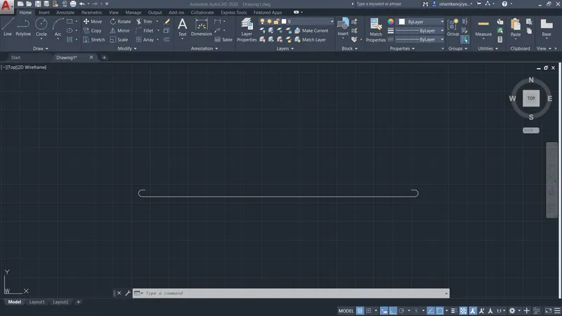
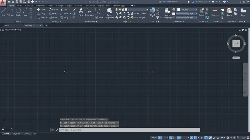
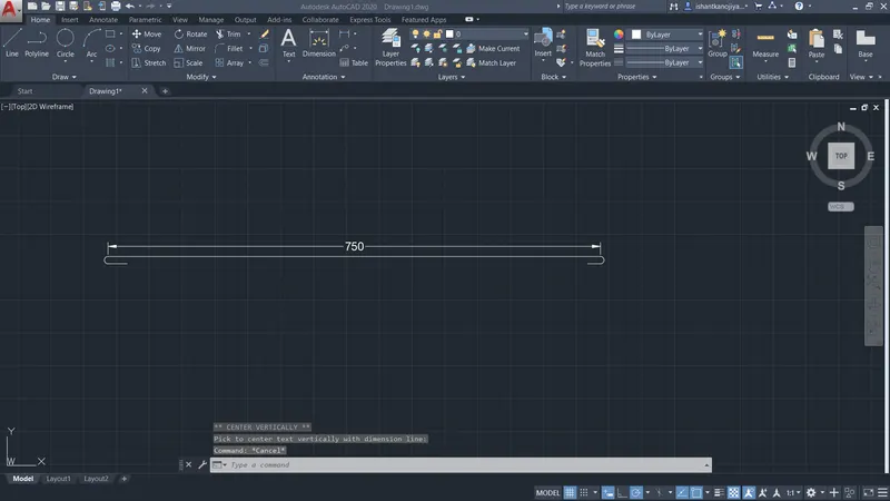
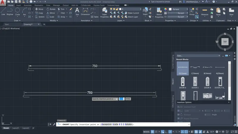
- SELECT LINE COMMAND> DISTANCE 750MM> SELECT OFFSET 18MM
- SELECT FLITE COMMAND> SPECIFY RADIUS 2MM> SELECT SELECT OBJESTS
- SELECT THE REFERENCE LINE DELECT IT
- SKETCH THE REST LINE
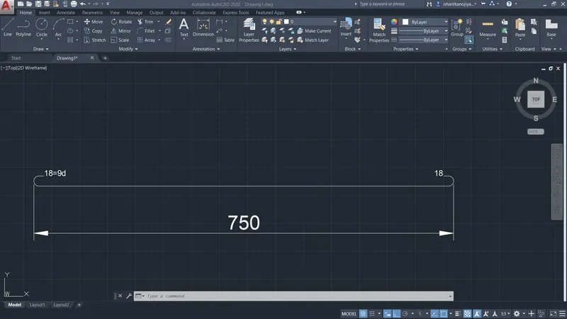
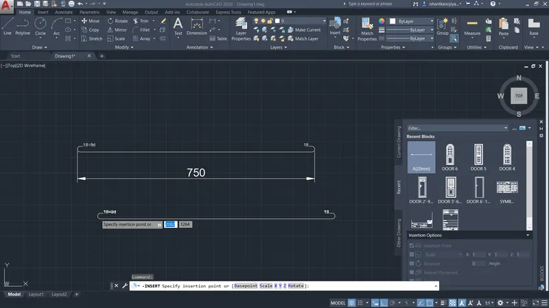
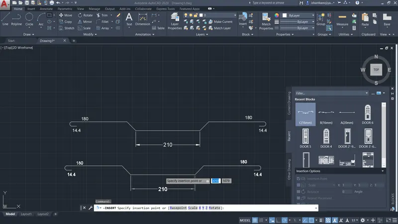
- NEXT DIAGRAM (B16mm)
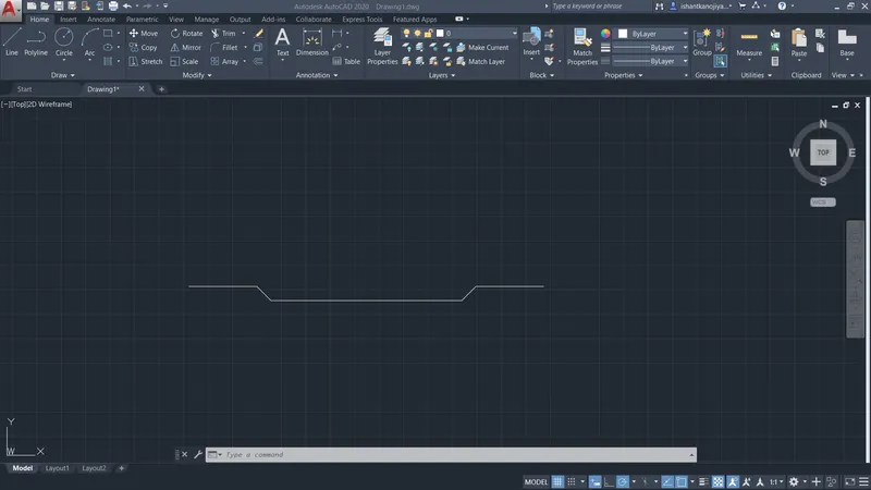
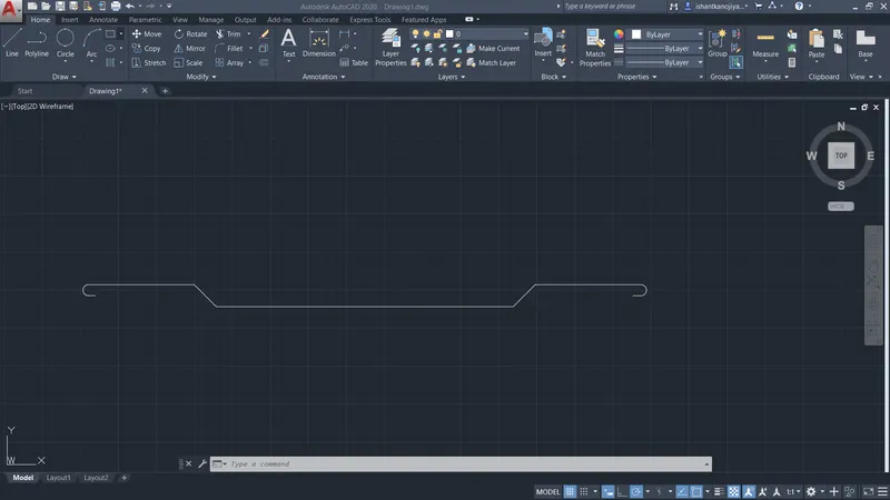
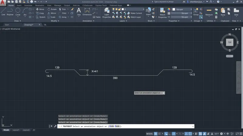
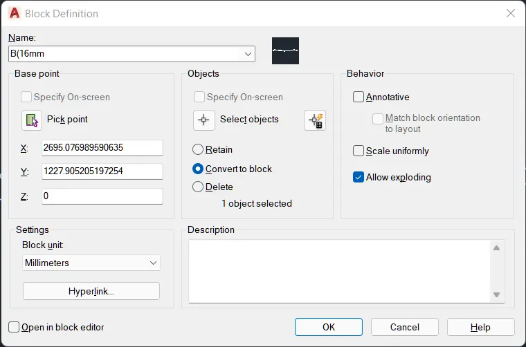
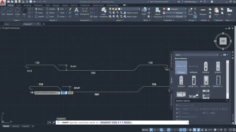
- SKETCHING (C 12mm)
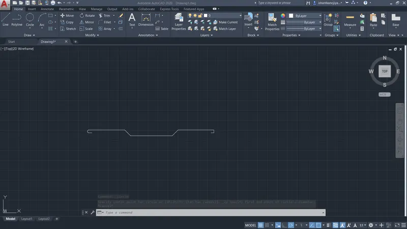
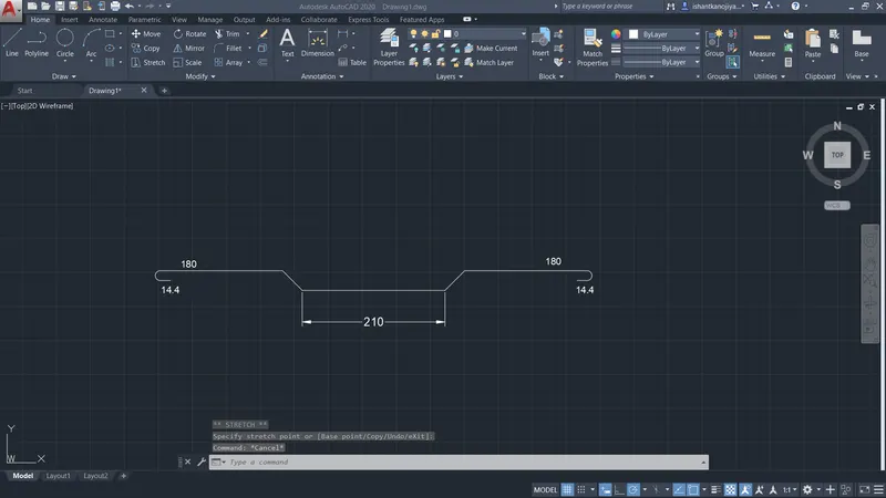
- SKETCHING (D 12mm)
- SKETCHING (E10mm)
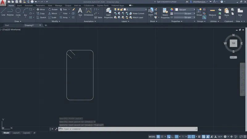
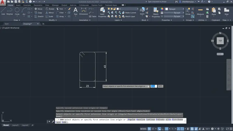
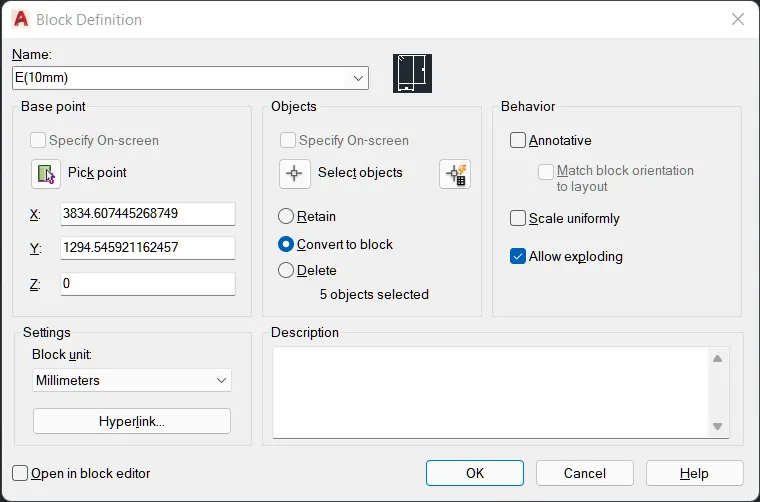
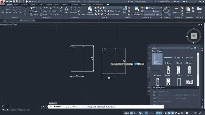
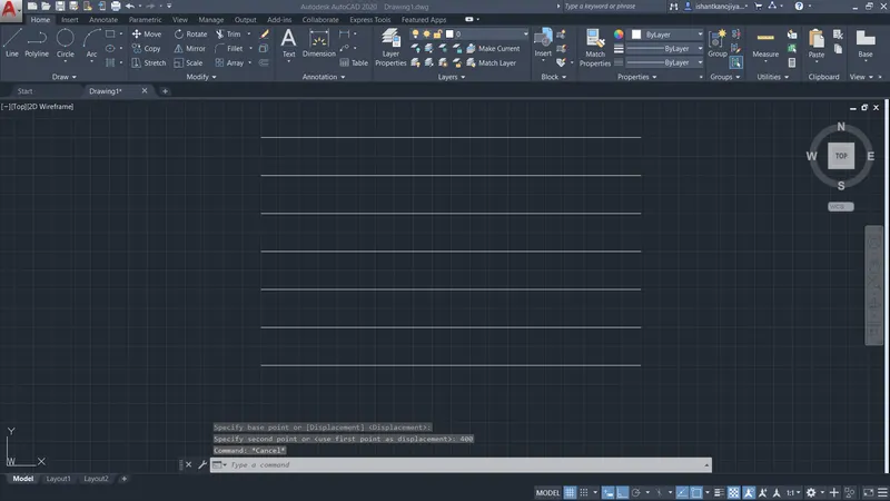
SKETCHING THE TABLE AND PLACE THE TAG (LIKE (NO OF BARS @ DIA),(TOTAL LENGTH), TOTAL WEIGHT)
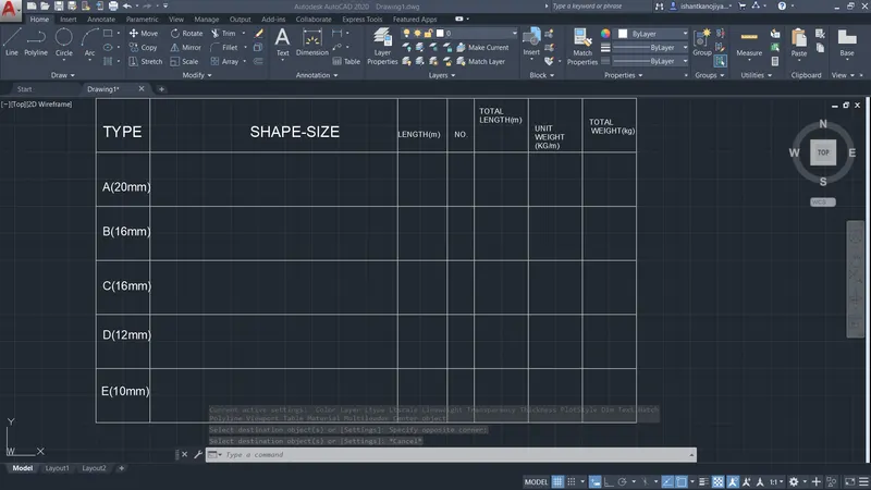

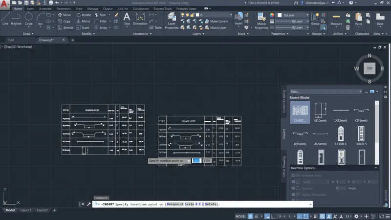
RESULT