Creating Bar Bending schedule, Different Door types, and Creation of standard drawing templates using AutoCad
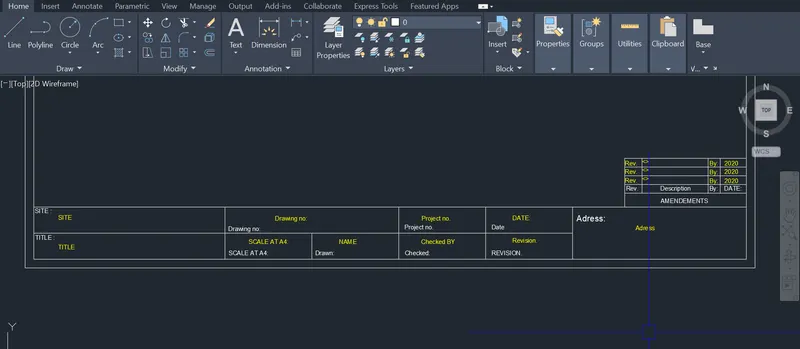
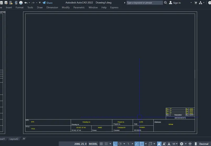
AIM & INTRODUCTION: To draw a templates as shown in Figures. Take the size of the title block as per industry standards or you can assume Use text and attributes wherever required and create the title block you need to save it as a block with names: Custom1_titleblock and Custom2_titleblock, respectively.
Procedure :
Command used:
- Line
- Rectangle
- Join
- Block
- Attdef
- Attedit
- Erase
- Trim
- Battman
- copy
- Mtext
- Open new drawing file
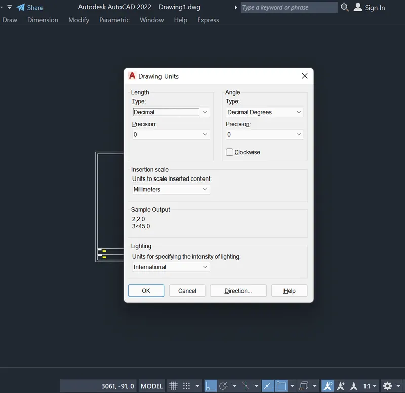
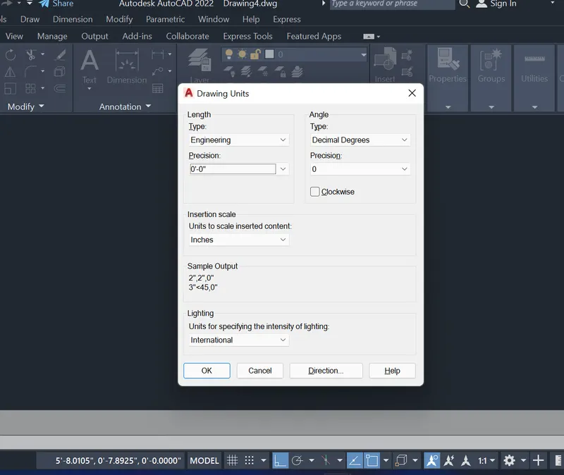
- Select units
- Un
- Creating a Custom-1 Title block Block
Image attached
- Draw a rectangle of standard size of A3 ( 297 x 420)
- Rectangle > specify point >297,420
- Offset > 5> select object: select rectangle > select inner side of rectangle
- Explode the previous rectangle by using explode command
- EXPLODE > select the inner rectangle > enter
- Create a table by offsetting the line
- Offset the inner vertical line in to 3 parts
- OFFSET > Select the inner vertical line > Specify distance: 100> Enter.
- Copy > select the line > Array > Enter number of items to array: 6> second point or [Fit]: 15
- Trim the unused lines by using “TRIM” command.
- OFFSET > the last line > Specify distance: 30> Enter.
- OFFSET > the last line > Specify distance: 10> Enter.
- Copy > select the line > Array > Enter number of items to array: 4> second point or [Fit]: 5
- Create text by “ MTEXT” command
Creating attribute text by using ATTDEF command:
- ATTDEF >
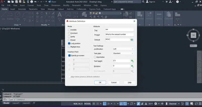 > specify location.
 - Repeat Attribute command for remaining text (For similar text we can copy the same attribute)
Create a block
- B >
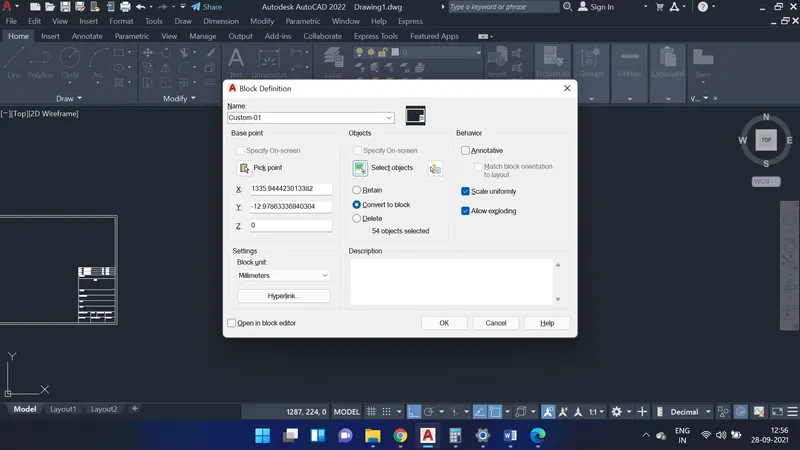 > select block in source option
 - Select object > select drawing > enter
- Specify base point > enter
- Creating a custom-2 Block
- Draw a rectangle of standard size of A3 ( 297 x 420)
- Rectangle > specify point >297,420
- Offset > 5> select object: select rectangle > select inner side of rectangle
- Explode the previous rectangle by using explode command
- EXPLODE > select the inner rectangle > enter
- Create a table by offsetting the line
- OFFSET > Select object: Select the vertical line > Specify distance : 100 > specify direction
- OFFSET > Select object: Select the last line > Specify distance : 100 > specify direction
- OFFSET > Select object: Select the last line > Specify distance : 100 > specify direction
- OFFSET > Select object: Select the horizontal line > Specify distance : 15 > specify direction
- OFFSET > Select object: Select the last line > Specify distance : 15 > specify direction
- OFFSET > Select object: Select the last line > Specify distance : 8 > specify direction
- Copy > select the line > Array > Enter number of items to array: 4> second point or [Fit]: 5
- Create text by “ MTEXT” command
Creating attribute text by using ATTDEF command:
- ATTDEF >
 > specify location
 - Repeat Attribute command for remaining text ( For similar text we can copy the same attribute )
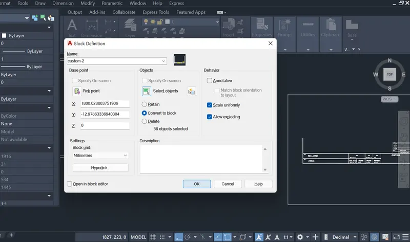
Create a block
- B > object ref image > select block in source option
- Select object > select drawing > enter
Specify base point > enter
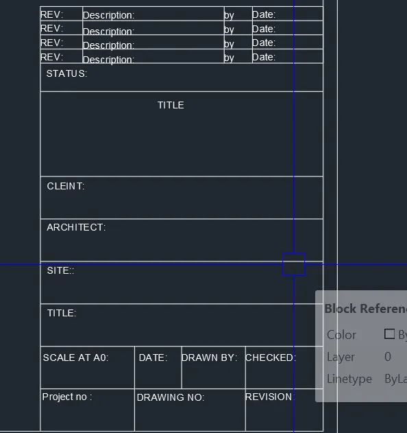
Result:
- Custom1_titleblock
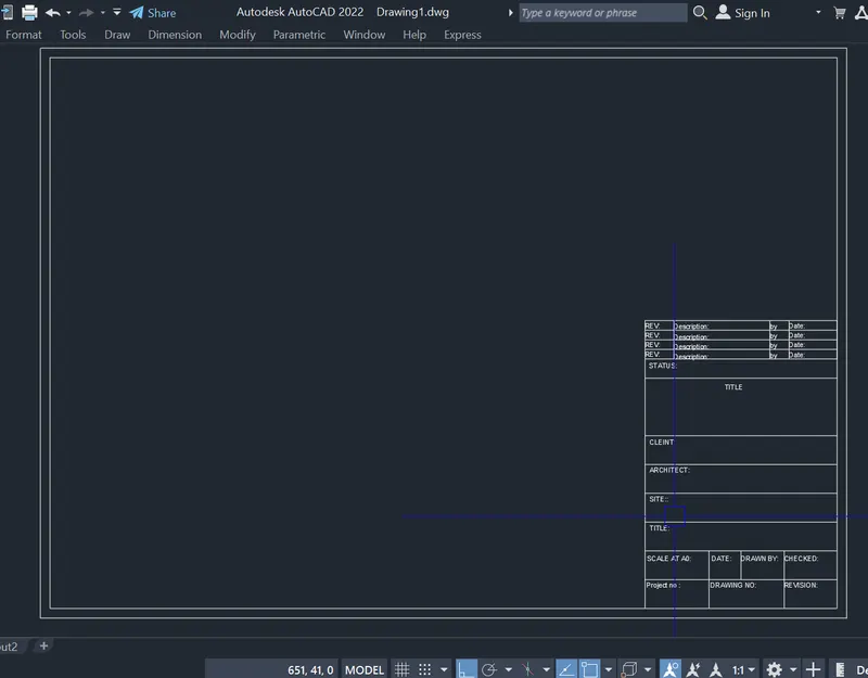
- Custom2_titleblock:
 +
+
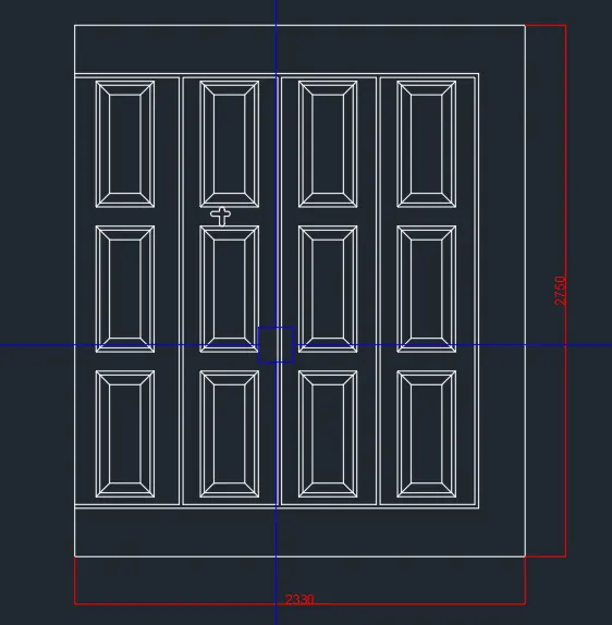
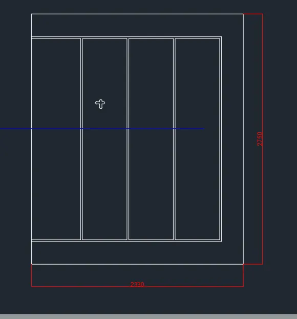
AIM & INTRODUCTION:To draw the doors type for warehouse as shown in the Figure. You need to create each door type as per standard size or given dimensions and create the blocks of this door type after creating them.
Procedure :
Open new drawing file
- Select units
- Un
- Draw a rectangle of size of 2330mm x 2750mm
- Rectangle > specify point >2330,2750
- Offset > Specify distance:250> select object: select rectangle > select inner side of rectangle
- Explode the previous rectangle by using explode command
- EXPLODE > select the inner rectangle > enter
- Extend the horizontal lines
- EXTEND > select the base line > select the extend line
- Divide the line in to four parts
- DIV > Select the horizontal line > Enter number of parts:4
- Draw the lines which is offset from points at a distance
- XL > vertical > intersect the line in vertical direction
- Offset > specify distance :10 >select the line > specify at both directions
- Do the same procedure for all 4 points
- Draw a rectangle of 300 X 650 mm
- Offset > Specify distance:20 > select object: select rectangle > select inner side of rectangle
- Offset > Specify distance:50> select object: select rectangle > select inner side of rectangle
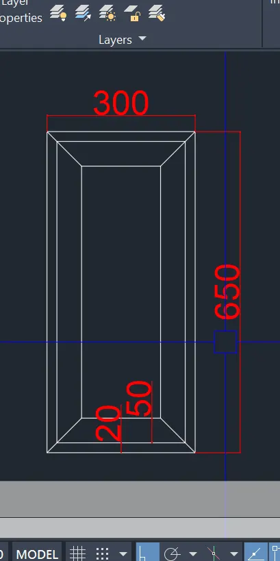
- Join tie corners of given rectangle with line command.
Create a block for door-1
- B >
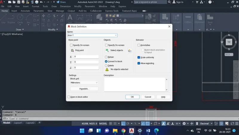 > select block in source option
 - Select object > select drawing > enter
- Specify base point > enter
Result:
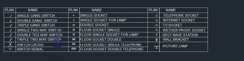
AIM & INTRODUCTION: To create block table as shown in figure by using auto cad
Procedure :
Open new drawing file
- Select units
- Un
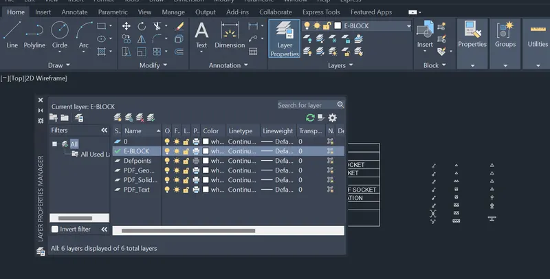
- Create a layer
- LA > Select new layer option > Name the layer.
- Create a block with lines and circles
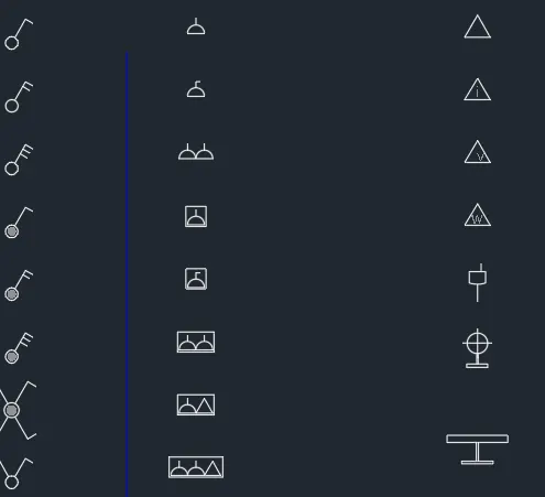
- Create a table with lines
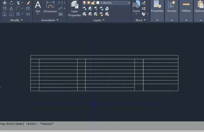
Insert a block in table
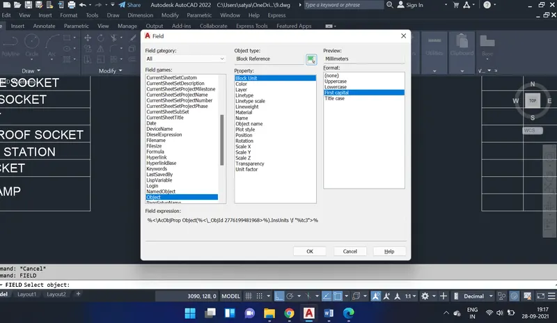
Insert name the block
- Feild > select the object option in feild name> select object: select the block to display > select Object name in property >select first capital in format
OK > Specify point in table
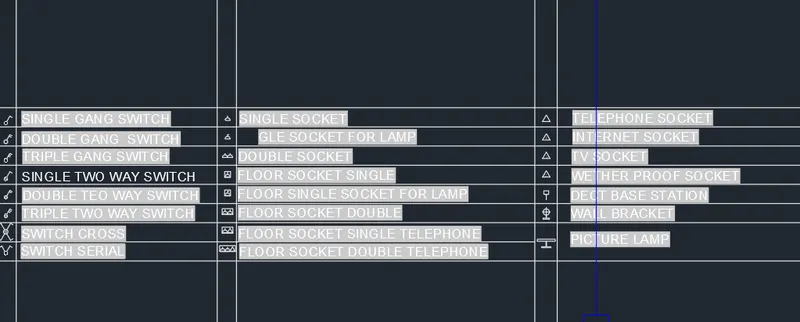
Explode the text to remove the background of text
Result:
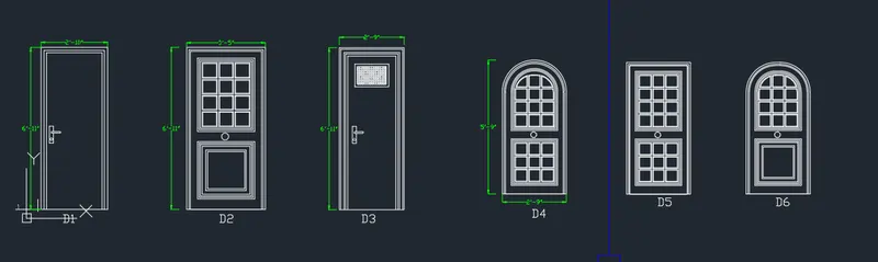
AIM & INTRODUCTION: To create block table as shown in figure by using auto cad
Procedure :
Open new drawing file in Imperical
- Select units
- Un
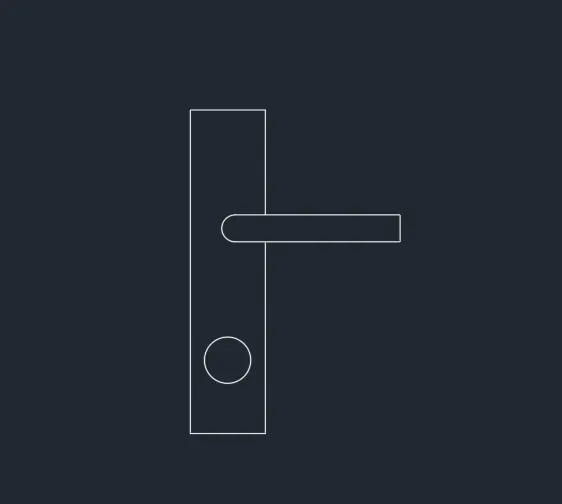
1) Creating a door (D1):
Rectangle > Specify point > 2'-10",6'-11"
Offset >2">select previous rectangle > Specify direction
Offset >1">select previous rectangle > Specify direction
Creating a door lock (D1):
Rectangle > Specify point >2",9"
Rectangle > Specify point >1",5"
Rotate > select base point > angle :-90
explode rectangle
fillet > radius> 1" > selecr corners of horizontal lines > enter
circle > specify center point > enter radius : 1"
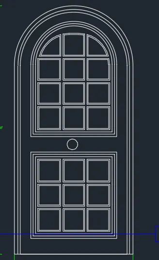
2) Creating a door (D2):
Rectangle > Specify point > 2'-10",6'-11"
Offset >2">select previous rectangle > Specify direction
Offset >1">select previous rectangle > Specify direction
Offset >3">select previous rectangle > Specify direction
Offset >2">select previous rectangle > Specify direction
Offset >1">select previous rectangle > Specify direction
circle > specify center point > enter radius : 2"
Rectangle > Specify point >8",8"
Offset >1">select previous rectangle > Specify direction
ARRAY >SELECT THE RECTANGLE OF 8".8"> RECTANGLE > SPECIFY BETWEEN DISTANCE AND NUMBER OF ROWS AND CIOLUMNS IN OPTION
Rectangle > Specify point > 2'-5",2'-6"
Offset >1">select previous rectangle > Specify direction
Offset >1">select previous rectangle > Specify direction
Offset >2">select previous rectangle > Specify direction
Offset >1">select previous rectangle > Specify direction
TRIM the unused lines
Extend the bottom lines
3) Creating a door (D3):
Rectangle > Specify point > 2'-10",6'-11"
Offset >2">select previous rectangle > Specify direction
Offset >1">select previous rectangle > Specify direction
Creating a door lock (D3):
Rectangle > Specify point >2",9"
Rectangle > Specify point >1",5"
Rotate > select base point > angle :-90
explode rectangle
fillet > radius> 1" > selecr corners of horizontal lines > enter
circle > specify center point > enter radius : 1"
Create rectangle 1',1'-5"
Rectangle > Specify starting point >1',1'-5"
Offset > Specify distance :1" >specify direction
Hatch > specify internal area > select angle pattren> set angle as 45
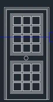
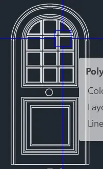
Result:
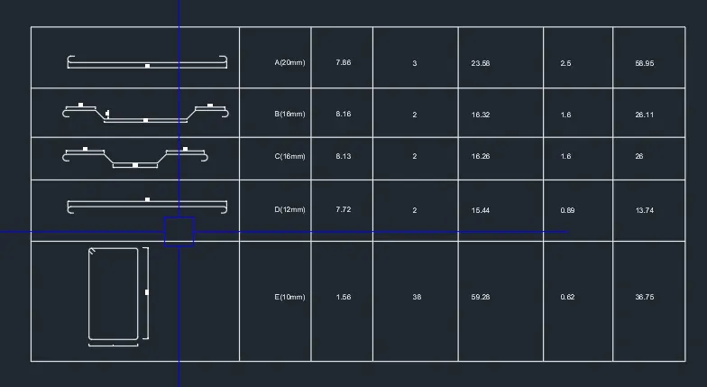
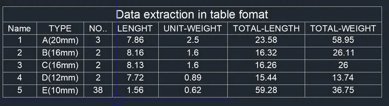
AIM & INTRODUCTION: To draw each shape as a block as shown in the Figure and insert the block in a table.
Procedure :
Create shapes as per dimensions by using line and arc command
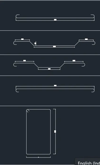
Create attributes for the shapes
- ATTDEF > > specify location.
- Repeat Attribute command for remaining text (For similar text we can copy the same attribute)
- Create a table using lines and insert
- extract the data of attributes
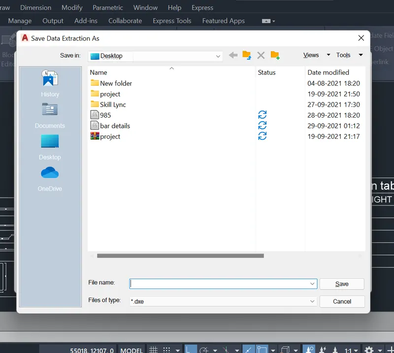
- select location
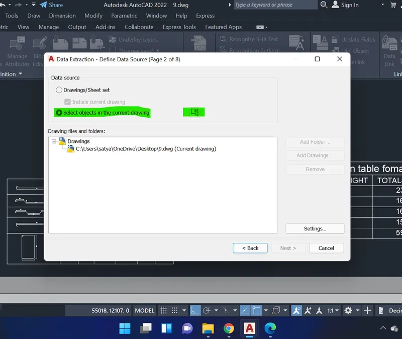
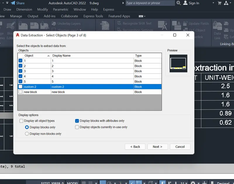
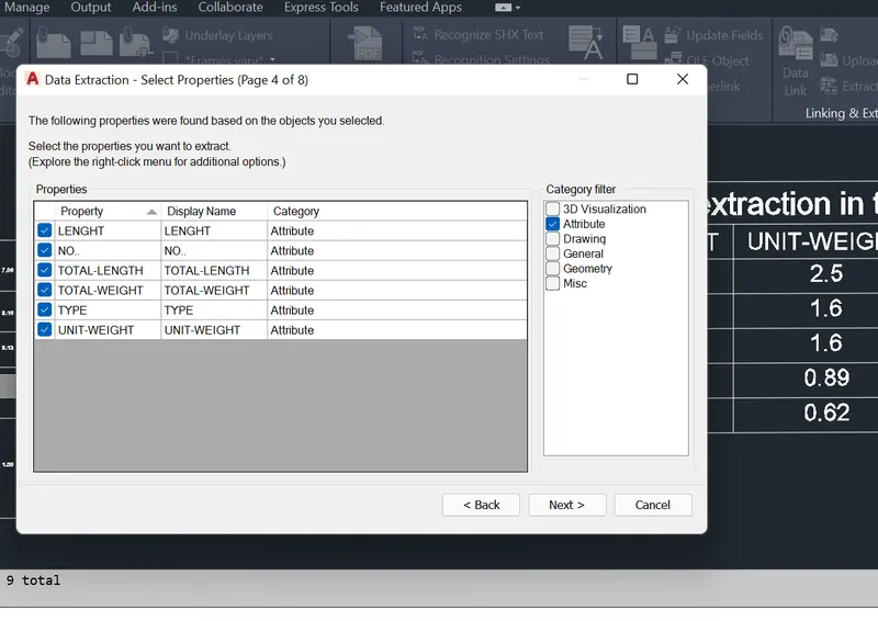

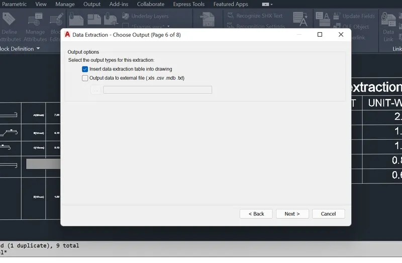
- SPECIFY POINT TO PLACE TABLE DETAILS
- Results: