Creating Bar Bending schedule, Different Door types, and Creation of standard drawing templates using AutoCad
TITLE TEMPLATE BLOCK
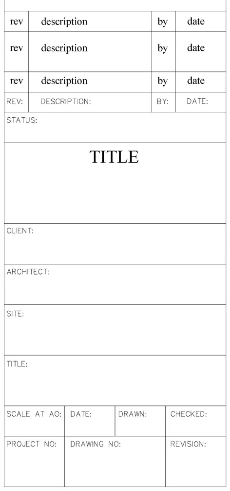
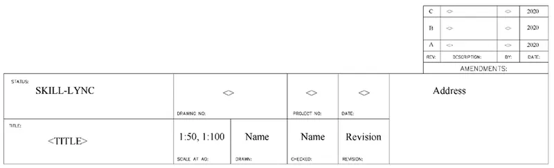
Aim: To create the templates as shown in figures using text and attributes and saving it as a block in AutoCAD.
Introduction: The templates are created in AutoCAD using various tools / commands. The size of the title block is assumed as per the size of the paper. The procedure of drawing is explained and the final result is given.
Commands used:
Block
Insert
Attributes
Field
Rectangle
Line
Text
Array
Mirror
Copy
Offset
To create a template of title block to the paper size of 210 x 297 follow the below procedure
Procedure:
Step 1
Type unit or UN in the command line and press enter
Set type of unit as decimal and precision as 0
In insertion scale set unit as millimeter.
Set the limits by typing LIM specify the left corner points and right corner points
Type Z in command line press enter then A to zoom.
Step 2
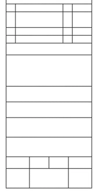
Type REC in the command line then press enter to invoke rectangle tool
Specify the first point on the screen
Type D and Press Enter to specify dimension of rectangle
Specify first length of 100 then Enter
Specify rectangle second length 210
Draw the rows and columns to fill the texts as per requirement
Step 3
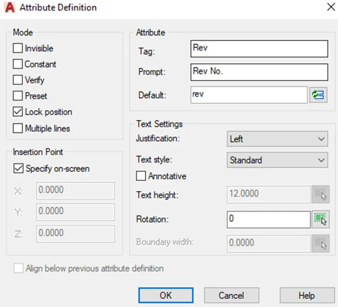
Create attributes to create the text inside it
Type ATTDEF in the command line to invoke attribute definition dialogue box.
Follow the same process for all texts. Type rev, description, by, date on the first row by text height 3 and Title text height of 5, use style Times New Roman. Then remaining with text height 2.5 using Dim font style.
Use multiline text to create remaining text to fill the cells of the template.
Step 4
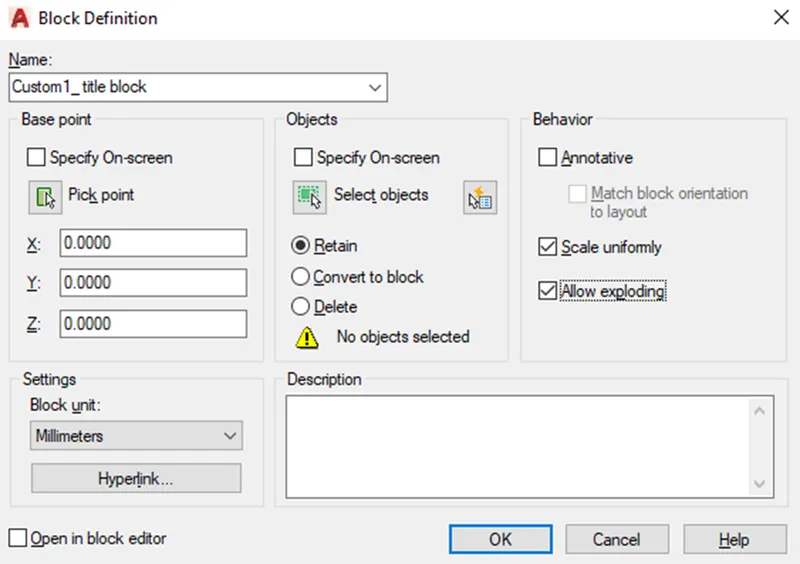
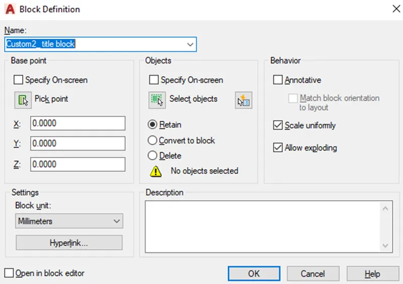
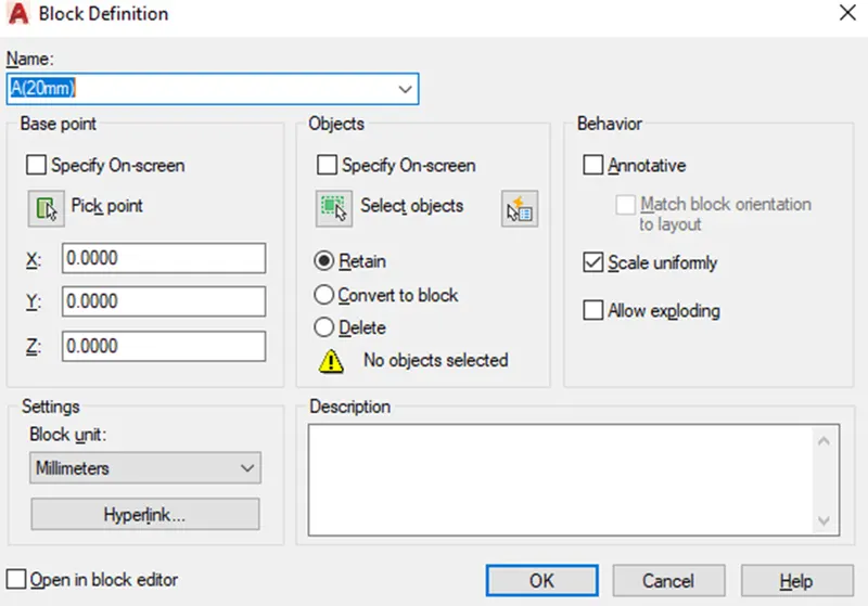
Type B in the command line to create block by block definition dialogue box. Create a block with name as Custom1_ title block, select pick point to insert the block after creating, select the object including the text. Give scale uniformly and tick allow exploding. Select convert to block option.
Step 5
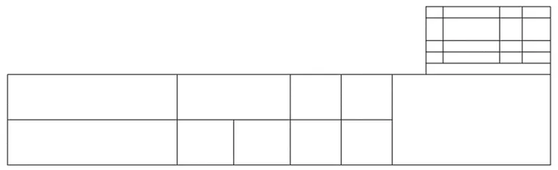
Repeat the same steps followed to create Custom1_ title block to create Custom2_ title block
Type REC in the command line then press enter to invoke rectangle tool
Specify the first point on the screen
Type D and Press Enter to specify dimension of rectangle
Specify first length of 297 then Enter
Specify rectangle second length 50
Draw the rows and columns to fill the texts as per requirement
Step 6
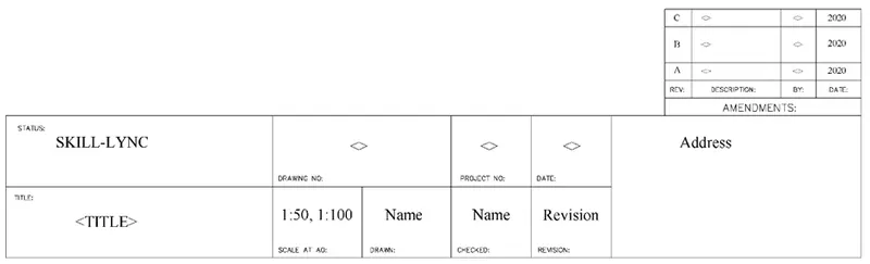
Use multiline text to create text elements. Type Status, Tile, drawing no, Scale, Project No., Date in the cells of the template.
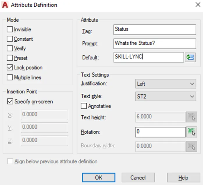
Create attributes to create the text inside it
Type ATTDEF in the command line to invoke attribute definition dialogue box.
Follow the same process for all texts. Type Skill Lync, Title, Name, date with text height of 4, use style Times New Roman. Then remaining with text height 2 using Dim font style.
Step 7
Type B in the command line to create block by block definition dialogue box. Create a block with name as Custom2_ title block, select pick point to insert the block after creating, select the object including the text. Give scale uniformly and tick allow exploding. Select convert to block option.
RESULTS
DOORS FOR WAREHOUSE
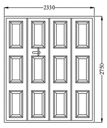
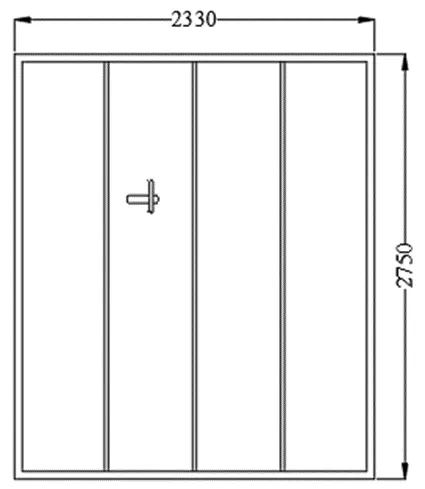
Aim: To create the doors type for warehouse as shown in the Figure as per given dimensions and saving it as a block in AutoCAD.
Introduction: The doors type for warehouse are created in AutoCAD using various tools / commands. Each door type is created as per given dimensions. The procedure of drawing is explained and the final result is given.
Commands used:
Rectangle
Line
Polyline
Offset
Trim
Fillet
Copy
Move
Divide
Explode
Procedure:
Step 1
Type unit or UN in the command line and press enter
Set type of unit as decimal and precision as 0
In insertion scale set unit as millimeter.
Set the limits by typing LIM specify the left corner points and right corner points
Type Z in command line press enter then A to zoom.
Step 2
Type REC in the command line then press enter to invoke rectangle tool
Specify the first point on the screen
Type D and Press Enter to specify dimension of rectangle
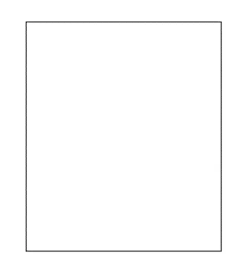
Specify first length of 2330 then Enter
Specify rectangle second length 2750
Step 3
Offset rectangle to 50 mm as a frame.
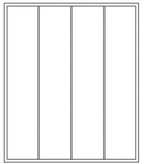
Use divide DIV command to divide the top line into 4 segments. From the division point, draw lines vertically to divide it into shutters of 25 mm.
Step 4
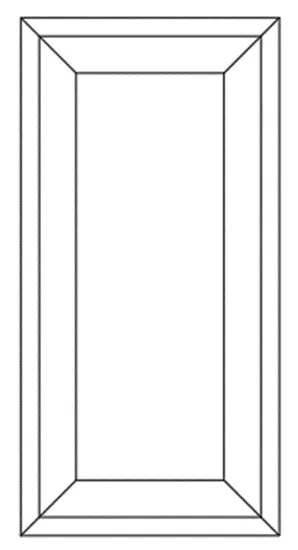
Create a rectangle of 350 x 700 to create the panels. Offset 25 mm from the 1st rectangle and offset 50 mm from the 2nd rectangle. Draw lines joining the corners of the outside and inside rectangle.
Step 5
Use copy command and paste in each shutter panel
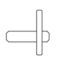
Create handle using rectangle and chamfer command
Type DIM in the command box and press enter to measure the dimensions
Step 6
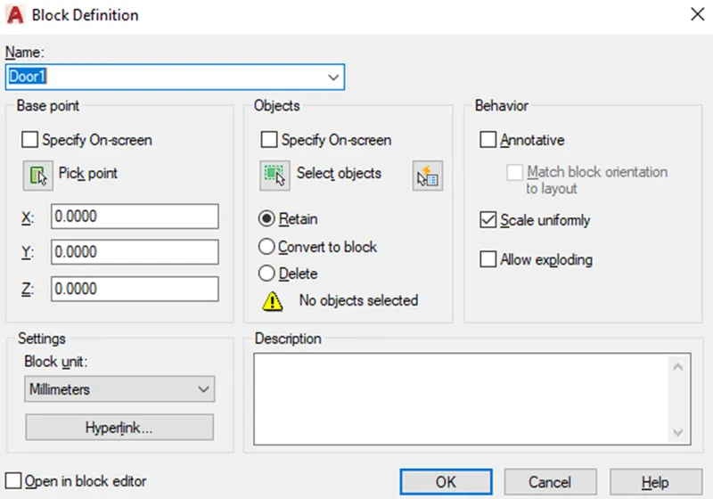
Type B in the command line to create block by block definition dialogue box. Create a block with name as Door1 and Door 2.
RESULTS
ELECTRICAL SYMBOLS LEGEND
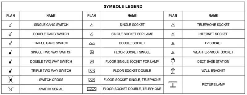
Aim: To create each electrical symbol using AutoCAD and saving them as block
Introduction: Each electrical symbol is created in AutoCAD using various tools / commands. Each door type is created as per given dimensions. The procedure of drawing is explained and the final result is given.
Commands used:
Rectangle
Line
Polyline
Offset
Trim
Fillet
Copy
Move
Divide
Explode
Circle
Procedure:
Step 1
Type unit or UN in the command line and press enter
Set type of unit as decimal and precision as 0
In insertion scale set unit as millimeter.
Set the limits by typing LIM specify the left corner points and right corner points
Type Z in command line press enter then A to zoom.
Step 2
Draw each electrical symbol using draw tools and modify tools in AutoCAD and arrange them in Legend Table.
Save each symbol as block with the respective name
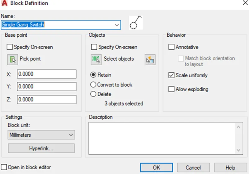
Step 3
Draw a table to create Electrical Symbols Legend with required rows and columns
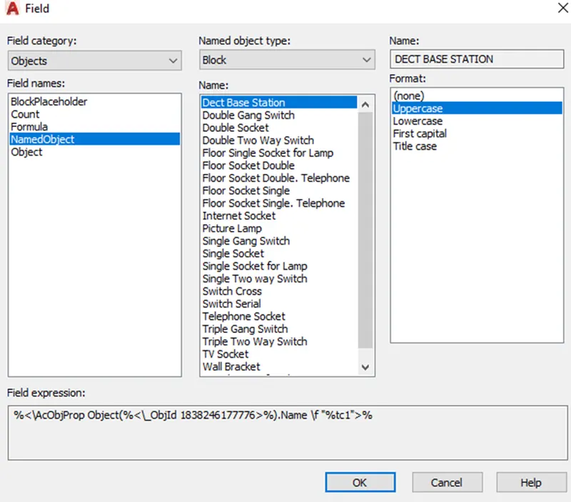
Inert Symbols to the respective cells of the table
Use Field to insert name of the symbol given while creating Block
Step 4
Add title and Header to the Table to complete the Table
RESULT
DOORS FOR RESIDENTIAL BUILDING
Aim: To create the doors type for residential building as shown in the Figure as per given dimensions and saving it as a block in AutoCAD.
Introduction: The doors type for residential building are created in AutoCAD using various tools / commands. Each door type is created as per given dimensions. The procedure of drawing is explained and the final result is given.
Commands used:
Rectangle
Line
Polyline
Offset
Trim
Fillet
Copy
Move
Divide
Explode
Circle
Procedure:
Step 1
Type unit or UN in the command line and press enter
Set type of unit as Engineering and precision as 0’0”
In insertion scale set unit as Inch.
Set the limits by typing LIM specify the left corner points and right corner points
Type Z in command line press enter then A to zoom.
Step 2
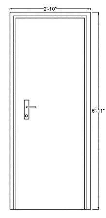
Draw rectangle with dimension 2'10" and 6' 11".
Draw offset 1.5" for frame and draw offset 1" for shutter.
Draw lock using two rectangles perpendicular to each other and fillet the corners with radius 0.1"and circle.
Use DIM command to provide dimensions
Create it as block and give name as RD1 then pick insert point.
Step 3
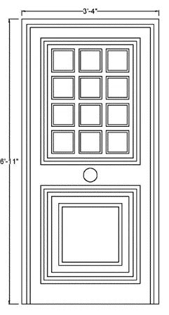
Draw rectangle with dimension 3' 4" and 6' 11".
Draw offset 1.5" for frame and draw offset 1" for shutter.
Draw square for panel 2' 5" and 3' 0.9", then offset 1" two times.
Draw a rectangle 6.7" x 6.7", offset 0.5".
Copy it with copy command to create multiple copies, Place 3 columns horizontally and 4 rows vertically.
For the second panel draw a rectangle of 2'5" x 2'4.6". Offset 1" 2 times and 1.25” another time.
Draw another rectangle inside this of 1'6.5" x 1' 6.1" and offset 1".
Draw lock by circle in between the two panels.
Use DIM command to provide dimensions
Create it as block and give name as RD2 then pick insert point.
Step 4
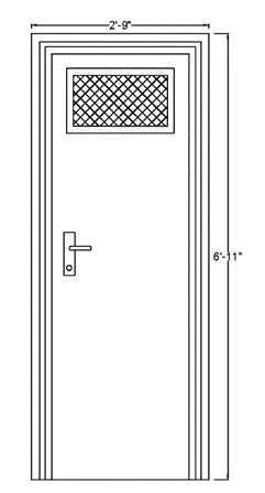
Draw rectangle with dimension 2'10" and 6' 11".
Draw offset 1.5" for frame and draw offset 1" for shutter.
Draw lock using two rectangles perpendicular to each other and fillet the corners with radius 0.1"and circle.
Draw a rectangle at the top for ventilation 1'8" x 1', give offset 1" for thickness.
Hatch inside the rectangle.
Use DIM command to provide dimensions
Create it as block and give name as RD1 then pick insert point.
Use DIM command to provide dimensions
Create it as block and give name as RD3 then pick insert point.
Step 5
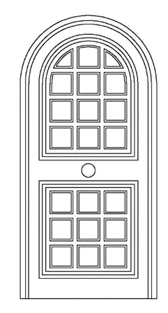
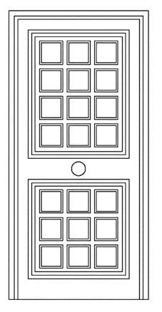
Draw rectangle with dimension 3' 4" and 6' 11"
Draw offset 1.5" for frame and draw offset 1" for shutter.
Draw square for panel 2' 5" and 3' 0.9", then offset 1" two times.
Draw a rectangle 6.7" x 6.7", offset 0.5".
Copy it with copy command to create multiple copies, Place 3 columns horizontally and 4 rows vertically.
Draw arc using start end direction and offset it according to previous offset dimensions
Trim the extra lines come out of the arc line
For the second panel draw a rectangle of 2'5" x 2'4.6". Offset 1" 2 times
Copy the square panel from above and paste it as 3 rows and 3 columns
Draw lock by circle in between the two panels.
Use DIM command to provide dimensions
Create it as block and give name as RD4 then pick insert point.
Step 5
Draw rectangle with dimension 3' 4" and 6' 11"
Draw offset 1.5" for frame and draw offset 1" for shutter.
Draw square for panel 2' 5" and 3' 0.9", then offset 1" two times.
Draw a rectangle 6.7" x 6.7", offset 0.5".
Copy it with copy command to create multiple copies, Place 3 columns horizontally and 4 rows vertically.
For the second panel draw a rectangle of 2'5" x 2'4.6". Offset 1" 2 times
Copy the square panel from above and paste it as 3 rows and 3 columns
Draw lock by circle in between the two panels.
Use DIM command to provide dimensions
Create it as block and give name as RD5 then pick insert point.
Step 5
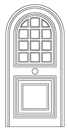
Draw rectangle with dimension 3' 4" and 6' 11"
Draw offset 1.5" for frame and draw offset 1" for shutter.
Draw square for panel 2' 5" and 3' 0.9", then offset 1" two times.
Draw a rectangle 6.7" x 6.7", offset 0.5".
Copy it with copy command to create multiple copies, Place 3 columns horizontally and 4 rows vertically.
Draw arc using start end direction and offset it according to previous offset dimensions
Trim the extra lines come out of the arc line
For the second panel draw a rectangle of 2'5" x 2'4.6". Offset 1" 2 times
Draw another rectangle inside this of 1'6.5" x 1' 6.1" and offset 1".
Draw lock by circle in between the two panels.
Use DIM command to provide dimensions
Create it as block and give name as RD6 then pick insert point.
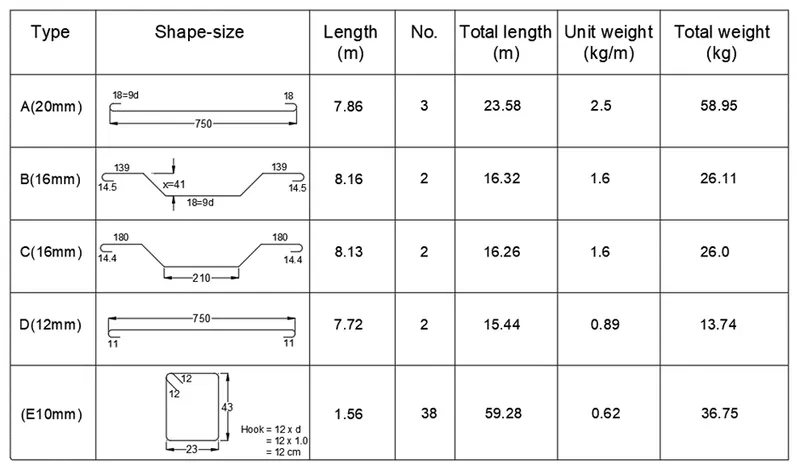
BAR BENDING SCHEDULE
Aim: To create the bar bending schedule as shown in the Figure as per given dimensions and saving it as a block in AutoCAD.
Introduction: The bar bending shapes are created in AutoCAD using various tools / commands. Each door type is created as per given dimensions. The procedure of drawing is explained and the final result is given.
Commands used:
Rectangle
Line
Polyline
Offset
Trim
Fillet
Copy
Move
Divide
Explode
Circle
Procedure:
Step 1
Type unit or UN in the command line and press enter
Set type of unit as Decimal and precision as 0
In insertion scale set unit as millimeter.
Set the limits by typing LIM specify the left corner points and right corner points
Type Z in command line press enter then A to zoom.
Step 2
Draw each bar bending shape using draw tools and modify tools in AutoCAD and arrange them in Table.
Save each shape as block with the respective name
Step 3
Draw a table to create bar bending shapes with required rows and columns
Inert Shape to the respective cells of the table
Use mtext to complete the table
Add title and Header to the Table to complete the Table
RESULT